RU178564U1 - EARTHING DEVICE - Google Patents
EARTHING DEVICE Download PDFInfo
- Publication number
- RU178564U1 RU178564U1 RU2017126725U RU2017126725U RU178564U1 RU 178564 U1 RU178564 U1 RU 178564U1 RU 2017126725 U RU2017126725 U RU 2017126725U RU 2017126725 U RU2017126725 U RU 2017126725U RU 178564 U1 RU178564 U1 RU 178564U1
- Authority
- RU
- Russia
- Prior art keywords
- contact element
- head
- tip
- diameter
- grounding
- Prior art date
Links
- 229910052751 metal Inorganic materials 0.000 claims description 15
- 239000002184 metal Substances 0.000 claims description 15
- 238000010079 rubber tapping Methods 0.000 claims description 8
- 150000001875 compounds Chemical class 0.000 claims description 3
- 238000007789 sealing Methods 0.000 claims description 3
- 230000007704 transition Effects 0.000 claims description 3
- 230000002093 peripheral effect Effects 0.000 claims description 2
- 238000006073 displacement reaction Methods 0.000 abstract description 4
- 238000009434 installation Methods 0.000 abstract description 4
- 239000000969 carrier Substances 0.000 abstract description 2
- 238000005452 bending Methods 0.000 description 2
- GLGNXYJARSMNGJ-VKTIVEEGSA-N (1s,2s,3r,4r)-3-[[5-chloro-2-[(1-ethyl-6-methoxy-2-oxo-4,5-dihydro-3h-1-benzazepin-7-yl)amino]pyrimidin-4-yl]amino]bicyclo[2.2.1]hept-5-ene-2-carboxamide Chemical compound CCN1C(=O)CCCC2=C(OC)C(NC=3N=C(C(=CN=3)Cl)N[C@H]3[C@H]([C@@]4([H])C[C@@]3(C=C4)[H])C(N)=O)=CC=C21 GLGNXYJARSMNGJ-VKTIVEEGSA-N 0.000 description 1
- 229910000838 Al alloy Inorganic materials 0.000 description 1
- 229910000861 Mg alloy Inorganic materials 0.000 description 1
- XAGFODPZIPBFFR-UHFFFAOYSA-N aluminium Chemical compound [Al] XAGFODPZIPBFFR-UHFFFAOYSA-N 0.000 description 1
- 229940125758 compound 15 Drugs 0.000 description 1
- 230000007246 mechanism Effects 0.000 description 1
- 238000005476 soldering Methods 0.000 description 1
Images


Classifications
-
- H—ELECTRICITY
- H01—ELECTRIC ELEMENTS
- H01R—ELECTRICALLY-CONDUCTIVE CONNECTIONS; STRUCTURAL ASSOCIATIONS OF A PLURALITY OF MUTUALLY-INSULATED ELECTRICAL CONNECTING ELEMENTS; COUPLING DEVICES; CURRENT COLLECTORS
- H01R4/00—Electrically-conductive connections between two or more conductive members in direct contact, i.e. touching one another; Means for effecting or maintaining such contact; Electrically-conductive connections having two or more spaced connecting locations for conductors and using contact members penetrating insulation
- H01R4/58—Electrically-conductive connections between two or more conductive members in direct contact, i.e. touching one another; Means for effecting or maintaining such contact; Electrically-conductive connections having two or more spaced connecting locations for conductors and using contact members penetrating insulation characterised by the form or material of the contacting members
- H01R4/66—Connections with the terrestrial mass, e.g. earth plate, earth pin
Landscapes
- Shielding Devices Or Components To Electric Or Magnetic Fields (AREA)
Abstract
Полезная модель относится к области радиоэлектронной аппаратуры и может использоваться при конструировании блоков и составных частей изделий радиоэлектронных средств (РЭС) на различных объектах-носителях общего машиностроения при монтаже в местах с ограниченным доступом в независимости от группы исполнения аппаратуры для закорачивания точек электрической схемы (модуля, блока) на корпус объекта-носителя, которые должны быть под потенциалом земли. Технический результат, на достижение которого направлено заявляемое техническое решение, заключается в повышении технологичности монтажа наконечника кабельного шины заземления на головке контактного элемента в местах с ограниченным доступом, исключающего смещение наконечника кабельного шины заземления. Достижение технического результата обеспечивается изменением конструкции ближайшего аналога. В отличие от прототипа, со стороны наружного торца головки контактного элемента выполнены отверстия, расположенные в ряд по окружности, симметрично центральному резьбовому отверстию, а наконечник кабельный шины заземления выполнен с фиксатором, размещенным в отверстии головки контактного элемента.The utility model relates to the field of electronic equipment and can be used in the design of blocks and components of products of electronic equipment (RES) on various objects-carriers of general engineering during installation in places with limited access, regardless of the group of equipment for shorting points of the electrical circuit (module, block) to the body of the carrier object, which should be under the ground potential. The technical result, to which the claimed technical solution is directed, is to increase the manufacturability of mounting the tip of the grounding cable on the head of the contact element in places with limited access, eliminating the displacement of the tip of the grounding cable. The achievement of the technical result is provided by a change in the design of the closest analogue. In contrast to the prototype, from the outer end of the head of the contact element, holes are made that are arranged in a row around the circumference, symmetrically to the central threaded hole, and the tip of the cable grounding bus is made with a latch located in the hole in the head of the contact element.
Description
Полезная модель относится к области радиоэлектронной аппаратуры и может использоваться при конструировании блоков и составных частей изделий радиоэлектронных средств (РЭС) на различных объектах-носителях общего машиностроения при монтаже в местах с ограниченным доступом в независимости от группы исполнения аппаратуры для закорачивания точек электрической схемы (модуля, блока) на корпус объекта-носителя, которые должны быть под потенциалом земли.The utility model relates to the field of electronic equipment and can be used in the design of blocks and components of products of electronic equipment (RES) on various objects-carriers of general engineering during installation in places with limited access, regardless of the group of equipment for shorting points of the electrical circuit (module, block) to the body of the carrier object, which should be under the ground potential.
Из уровня техники известен заземляющий зажим вводного устройства электрической машины (патент на изобретение RU № 1527678, МПК H01R 4/30, 1989 г.), содержащий подпорку и присоединительный болт с шайбами и гайками. Присоединительный болт выполнен сменным с возможностью продольного перемещения относительно подпорки.The grounding clamp of the input device of an electric machine is known from the prior art (patent for invention RU No. 1527678, IPC
Известен заземляющий зажим (патент на полезную модель RU № 81385, МПК H01R 4/30, 2008 г.), содержащий присоединительный болт с шайбой и гайкой, консольную подпорку с продольной прорезью шириной, равной диаметру присоединительного болта. Одним концом подпорка закреплена на корпусе заземляющего устройства, а на другом конце выполнены упоры, которые образованы путем загибания свободных концов подпорки. Под присоединительным болтом размещен кабельный наконечник с шейкой шириной, равной ширине прорези в подпорке. Зажимная часть кабельного наконечника выполнена в виде прямоугольной шайбы с буртиками, которые по высоте равны толщине консольной подпорки, а расстояние между буртиками равно ширине подпорки.Known grounding clamp (patent for utility model RU No. 81385, IPC
К недостаткам вышеперечисленных устройств можно отнести сложность конструкции, значительное переходное сопротивление контакта из-за количества переходов, а также недостаточно эффективный электрический контакт металлического корпуса и наконечника шины при климатических и механических воздействиях.The disadvantages of the above devices include the complexity of the design, significant contact resistance due to the number of transitions, as well as insufficiently effective electrical contact of the metal casing and tire tip under climatic and mechanical stresses.
Известно устройство (Рощин Г.И. «Несущие конструкции, механизмы и механические узлы ЭВА» - М; Сов. радио, 1980 г. Стр. 199-200 рис. 11.4б), содержащее металлический корпус с контактным элементом, ввернутым в направляющее отверстие в стенке металлического корпуса, крепящим монтажный лепесток. При этом контактный элемент выполнен в виде самонарезающего винта с потайной головкой с последующей герметизацией контактного соединения компаундом.A device is known (G. Roshchin, “Structural Structures, Mechanisms, and Mechanical Components of EVA” - M; Sov. Radio, 1980, pp. 199-200, Fig. 11.4b) containing a metal housing with a contact element screwed into a guide hole in the wall of the metal housing securing the mounting tab. In this case, the contact element is made in the form of a self-tapping screw with a countersunk head, followed by sealing the contact connection with a compound.
К недостаткам вышеуказанного устройства можно отнести недостаточно эффективный электрический контакт металлического корпуса и поверхности лепестка.The disadvantages of the above devices include insufficiently effective electrical contact of the metal housing and the surface of the petal.
Наиболее близким по технической сущности и достигаемым результатам к предлагаемому техническому решению является устройство заземляющее (патент на полезную модель RU № 145552, МПК H01R 4/66, H01R 4/38, 2014 г.), содержащее металлический корпус с контактным элементом, выполненным с головкой и цилиндрическим стержнем с самонарезающей резьбой на его боковой поверхности, ввернутым в предварительное цилиндрическое отверстие в стенке металлического корпуса, с последующей герметизацией контактного соединения компаундом. Контактный элемент со стороны наружного торца головки выполнен с центральным резьбовым отверстием или резьбовым стержнем для крепления наконечника шины заземления, а самонарезающая резьба на цилиндрическом стержне выполнена сужающейся на периферийных витках, с переходом цилиндрического стержня в усеченный конус с хвостовиком со стороны его наружного торца для заземляющего провода. Диаметр D цилиндра стержня и диаметр D1 выступов самонарезающей резьбы находятся в следующем соотношении:The closest in technical essence and the achieved results to the proposed technical solution is the grounding device (patent for utility model RU No. 145552, IPC
D/D1=0,7…0,9,D / D1 = 0.7 ... 0.9,
где D- диаметр цилиндра стержня;where D is the diameter of the cylinder of the rod;
D1 - диаметр выступов самонарезающей резьбы,D1 is the diameter of the protrusions of the self-tapping thread,
металлический корпус выполнен с предварительным цилиндрическим отверстием в стенке диаметром d, определяющимся следующим соотношением:the metal case is made with a preliminary cylindrical hole in the wall with a diameter of d, determined by the following ratio:
d=0,84-0,9D1,d = 0.84-0.9D1,
где d - диаметр направляющего отверстия в стенке корпуса.where d is the diameter of the guide hole in the wall of the housing.
Техническая проблема, решаемая созданием заявленной полезной модели, заключается в отсутствии ориентирования наконечника кабельного шины заземления на головке контактного элемента, приводящее к сложности монтажа в местах с ограниченным доступом, не исключающего смещение наконечника кабельного шины заземления.The technical problem solved by the creation of the claimed utility model is the lack of orientation of the tip of the cable grounding bus on the head of the contact element, which leads to the difficulty of installation in places with limited access, not excluding the displacement of the tip of the cable grounding bus.
Технический результат, на достижение которого направлено заявляемое техническое решение, заключается в повышении технологичности монтажа наконечника кабельного шины заземления на головке контактного элемента в местах с ограниченным доступом, исключающего смещение наконечника кабельного шины заземления.The technical result, to which the claimed technical solution is directed, is to increase the manufacturability of mounting the tip of the grounding cable on the head of the contact element in places with limited access, eliminating the displacement of the tip of the grounding cable.
Достижение технического результата обеспечивается изменением конструкции ближайшего аналога. В отличие от прототипа, со стороны наружного торца головки контактного элемента выполнены отверстия, расположенные в ряд по окружности, симметрично центральному резьбовому отверстию, а наконечник кабельный шины заземления выполнен с фиксатором, размещенным в отверстии головки контактного элемента.The achievement of the technical result is provided by a change in the design of the nearest analogue. In contrast to the prototype, from the outer end of the head of the contact element, holes are made that are arranged in a row around the circumference, symmetrically to the central threaded hole, and the tip of the cable grounding bus is made with a latch located in the hole in the head of the contact element.
Сущность полезной модели поясняется чертежами, гдеThe essence of the utility model is illustrated by drawings, where
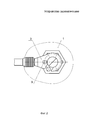
Фиг. 1 - устройство заземляющее с контактным элементом, выполненным с центральным резьбовым отверстием и с хвостовиком;FIG. 1 - grounding device with a contact element made with a Central threaded hole and with a shank;
Фиг. 2 - вид сверху Фиг. 1 (увеличено);FIG. 2 is a plan view of FIG. 1 (increased);
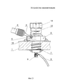
Фиг. 3 - устройство заземляющее с контактным элементом, выполненным с резьбовым стержнем;FIG. 3 - grounding device with a contact element made with a threaded rod;
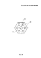
Фиг. 4 - вид сверху головки контактного элемента;FIG. 4 is a top view of the head of the contact element;
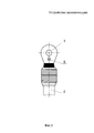
Фиг. 5 - металлический наконечник кабельной шины заземления со сквозным отверстием, расширяющийся к свободному округлому глухому краю;FIG. 5 - a metal tip of the grounding cable with a through hole, expanding to a free rounded blind edge;
Фиг. 6 - металлический наконечник кабельной шины заземления крючкообразной формы со сквозным пазом U-образного контура, расширяющийся к свободному краю;FIG. 6 - a metal lug of a hook-shaped grounding cable with a through groove of a U-shaped contour, expanding to the free edge;
Фиг. 7 - сечение А-А Фиг. 6;FIG. 7 is a section A-A of FIG. 6;
Фиг. 8 - металлический наконечник кабельной шины заземления вилкообразной формы со сквозным пазом U-образного контура, расширяющийся к свободному краю;FIG. 8 - a metal lug of a fork-shaped ground cable for grounding with a through groove of a U-shaped contour, expanding towards the free edge;
Устройство заземляющее содержит металлический корпус 1 (Фиг. 1, 2, 3), выполненный, например, из алюминиевого или магниевого сплава, в стенке которого выполнено предварительное цилиндрическое отверстие, кабельную шину заземления 2 (Фиг. 1, 2, 3, 5, 6, 8) с наконечником 3 (Фиг. 1, 2, 3, 5, 6, 8) и контактный элемент 4 (Фиг. 1).The grounding device contains a metal housing 1 (Fig. 1, 2, 3), made, for example, of aluminum or magnesium alloy, in the wall of which a preliminary cylindrical hole is made, a ground cable 2 (Fig. 1, 2, 3, 5, 6 , 8) with a tip 3 (Fig. 1, 2, 3, 5, 6, 8) and a contact element 4 (Fig. 1).
Наконечник 3 кабельной шины заземления 2 может быть выполненThe
- расширяющимся к свободному округлому глухому краю со сквозным отверстием (Фиг. 5);- expanding to a free rounded blind edge with a through hole (Fig. 5);
- расширяющимся к свободному округлому краю крючкообразной формы со сквозным пазом U-образного контура (Фиг. 6);- expanding to the free rounded edge of the hook-shaped shape with a through groove of the U-shaped contour (Fig. 6);
- расширяющимся к свободному краю вилкообразной формы со сквозным пазом U-образного контура (Фиг. 8).- expanding towards the free edge of the fork-shaped with a through groove of the U-shaped contour (Fig. 8).
При этом наконечник 3 кабельной шины заземления 2 имеет фиксатор 5 (Фиг. 1, 2, 3, 5, 6, 7, 8) в виде прямоугольной пластины, образованной просечкой с последующим отгибом.In this case, the
Контактный элемент 4 устройства заземляющего состоит из головки 6 (Фиг. 3, 4) и ступенчато примыкающего к ней стержня 7 (Фиг. 3) с цилиндрической боковой поверхностью, переходящей в боковую поверхность усеченного конуса, со стороны наружного торца которого может примыкать хвостовик 8 (Фиг. 3), направленный вдоль оси, на котором зафиксирован заземляющий провод 9 (Фиг. 3), например пайкой. На цилиндрической боковой поверхности стержня 7 контактного элемента 4 выполнена самонарезающая резьба.The
Со стороны наружного торца головки 6 контактного элемента 4 дополнительно выполнены глухие цилиндрические отверстия 10 (Фиг. 1, 3, 4), размещенные по окружности (Фиг. 4) с определенным шагом, например, 60° симметрично центральному резьбовому отверстию 11 (Фиг. 4) или резьбовому стержню 12 (Фиг. 3), обеспечивающие размещение в них фиксатора 5 наконечника 3 кабельной шины заземления 2.From the side of the outer end of the
Наконечник 3 кабельной шины заземления 2 зафиксирован на головке 6 контактного элемента 4 винтом 13 (Фиг. 1), ввернутым в ее центральное резьбовое отверстие 11 или гайкой 14 (Фиг. 3) разрезной пружинящей, завинченной на ее резьбовом стержне 12, при этом фиксатор 5 наконечника 3 кабельной шины заземления 2 размещен в одном из глухих цилиндрических отверстий 10 головки 6 контактного элемента 4.The
Наличие фиксатора 5 на наконечнике 3 кабельной шины заземления 2 повышает технологичность его монтажа на головке 6 контактного элемента 4 в местах с ограниченным доступом, исключая смещение.The presence of the
Для обеспечения дополнительной надежности и стабильности к климатическим и механическим воздействиям контактного соединения устройства заземляющего возможна его герметизация компаундом 15 (Фиг. 1) с одной или с двух поверхностей стенки металлического корпуса 1.To provide additional reliability and stability to climatic and mechanical influences of the contact connection of the grounding device, it is possible to seal it with compound 15 (Fig. 1) from one or two wall surfaces of the
Claims (7)
Priority Applications (1)
| Application Number | Priority Date | Filing Date | Title |
|---|---|---|---|
| RU2017126725U RU178564U1 (en) | 2017-07-25 | 2017-07-25 | EARTHING DEVICE |
Applications Claiming Priority (1)
| Application Number | Priority Date | Filing Date | Title |
|---|---|---|---|
| RU2017126725U RU178564U1 (en) | 2017-07-25 | 2017-07-25 | EARTHING DEVICE |
Publications (1)
| Publication Number | Publication Date |
|---|---|
| RU178564U1 true RU178564U1 (en) | 2018-04-11 |
Family
ID=61974640
Family Applications (1)
| Application Number | Title | Priority Date | Filing Date |
|---|---|---|---|
| RU2017126725U RU178564U1 (en) | 2017-07-25 | 2017-07-25 | EARTHING DEVICE |
Country Status (1)
| Country | Link |
|---|---|
| RU (1) | RU178564U1 (en) |
Cited By (1)
| Publication number | Priority date | Publication date | Assignee | Title |
|---|---|---|---|---|
| RU214449U1 (en) * | 2022-01-17 | 2022-10-28 | Российская Федерация, от имени которой выступает Министерство обороны Российской Федерации | Grounding device |
Citations (5)
| Publication number | Priority date | Publication date | Assignee | Title |
|---|---|---|---|---|
| SU636720A1 (en) * | 1977-04-25 | 1978-12-05 | Anatskij Aleksej | Portable earthing terminal |
| SU1527678A1 (en) * | 1987-08-03 | 1989-12-07 | Ленинградское Проектно-Экспериментальное Отделение Всесоюзного Государственного Научно-Исследовательского И Проектного Института "Вниипроектэлектромонтаж" | Ground terminal of electric machine input device |
| EP0445376A1 (en) * | 1990-03-09 | 1991-09-11 | KRONE Aktiengesellschaft | Connector |
| RU81385U1 (en) * | 2008-04-02 | 2009-03-10 | Федеральное государственное учреждение "Федеральный государственный научно-исследовательский испытательный центр радиоэлектронной борьбы и оценки эффективности снижения заметности" Министерства обороны Российской Федерации (ФГУ "ФГНИИЦ РЭБ ОЭСЗ" Минобороны России) | GROUND CLAMP |
| RU145552U1 (en) * | 2014-04-01 | 2014-09-20 | Открытое акционерное общество "Государственный Рязанский приборный завод" | EARTHING DEVICE |
-
2017
- 2017-07-25 RU RU2017126725U patent/RU178564U1/en active
Patent Citations (5)
| Publication number | Priority date | Publication date | Assignee | Title |
|---|---|---|---|---|
| SU636720A1 (en) * | 1977-04-25 | 1978-12-05 | Anatskij Aleksej | Portable earthing terminal |
| SU1527678A1 (en) * | 1987-08-03 | 1989-12-07 | Ленинградское Проектно-Экспериментальное Отделение Всесоюзного Государственного Научно-Исследовательского И Проектного Института "Вниипроектэлектромонтаж" | Ground terminal of electric machine input device |
| EP0445376A1 (en) * | 1990-03-09 | 1991-09-11 | KRONE Aktiengesellschaft | Connector |
| RU81385U1 (en) * | 2008-04-02 | 2009-03-10 | Федеральное государственное учреждение "Федеральный государственный научно-исследовательский испытательный центр радиоэлектронной борьбы и оценки эффективности снижения заметности" Министерства обороны Российской Федерации (ФГУ "ФГНИИЦ РЭБ ОЭСЗ" Минобороны России) | GROUND CLAMP |
| RU145552U1 (en) * | 2014-04-01 | 2014-09-20 | Открытое акционерное общество "Государственный Рязанский приборный завод" | EARTHING DEVICE |
Cited By (1)
| Publication number | Priority date | Publication date | Assignee | Title |
|---|---|---|---|---|
| RU214449U1 (en) * | 2022-01-17 | 2022-10-28 | Российская Федерация, от имени которой выступает Министерство обороны Российской Федерации | Grounding device |
Similar Documents
| Publication | Publication Date | Title |
|---|---|---|
| EP4226466A1 (en) | Contact connector | |
| EP2488789B1 (en) | Led lamp | |
| US3426321A (en) | Electrical wiring device having improved captured screw terminals | |
| US8777642B2 (en) | Electrical connector | |
| RU178564U1 (en) | EARTHING DEVICE | |
| RU145552U1 (en) | EARTHING DEVICE | |
| EP1709711B1 (en) | Device for connecting a coaxial cable to a housing | |
| DE112012002900B4 (en) | Mounting arrangement for a capacitor | |
| EP2694874B1 (en) | Device for fastening and contacting a lighting means and/or a lighting module, and lamp | |
| RU214449U1 (en) | Grounding device | |
| US1651314A (en) | Electrical switch | |
| WO2020193685A1 (en) | Mounting device and method for mounting a nut on a screw of a battery assembly, and battery assembly | |
| RU161832U1 (en) | EARTHING DEVICE | |
| EP0923105B1 (en) | Compact low pressure discharge lamp | |
| US3346835A (en) | Electrical connector | |
| DE29806397U1 (en) | Cable lug | |
| RU134354U1 (en) | CONTACT ELECTRICAL | |
| CN221530453U (en) | Anti-loosening wiring terminal | |
| RU97571U1 (en) | EARTHING DEVICE | |
| RU139194U1 (en) | CONTACT CLAMP ELECTRICAL | |
| EP2269268B1 (en) | High-current contact and electric component with a high-current contact | |
| AT83903B (en) | Elbows, plates and fasteners for electrical apparatus. | |
| DE803918C (en) | Socket for electric light bulbs, especially in mine hand lamps | |
| BR112020002798A2 (en) | wind power installation rotor blade, and wind power installation rotor blade protection system. | |
| CN213123992U (en) | Anti-rotation structure insulating column |