RU172100U1 - DEVICE FOR INCREASING EFFICIENCY AND RELIABILITY OF PROCESSING CRYPTOGRAMS - Google Patents
DEVICE FOR INCREASING EFFICIENCY AND RELIABILITY OF PROCESSING CRYPTOGRAMS Download PDFInfo
- Publication number
- RU172100U1 RU172100U1 RU2016107522U RU2016107522U RU172100U1 RU 172100 U1 RU172100 U1 RU 172100U1 RU 2016107522 U RU2016107522 U RU 2016107522U RU 2016107522 U RU2016107522 U RU 2016107522U RU 172100 U1 RU172100 U1 RU 172100U1
- Authority
- RU
- Russia
- Prior art keywords
- inputs
- outputs
- key
- request
- channels
- Prior art date
Links
Images

Abstract
Полезная модель относится к радиотехнике и может быть использована в системах с решающей обратной связью (РОС) для приема и обработки сигналов на каналах связи низкого качества.Технической задачей устройства является обеспечение требуемых режимов обработки информации меньшими аппаратными затратами.Технический результат достигается тем, что заявленное устройство повышения оперативности и достоверности обработки КРГ включает две параллельно расположенные линии, содержащие каждая дешифратор комбинации «Запрос», анализатор признака соответствия, накопитель, два переключателя, логический элемент «И», три логических элемента «ИЛИ», два ключа, причем информационный вход решающей обратной связи первого канала соединен соответственно с входами накопителя, анализатора признака соответствия, дешифратора команды «Запрос» первой линии, а информационный вход решающей обратной связи второго канала соединен соответственно с входами накопителя, анализатора признака соответствия, дешифратора команды «Запрос» второй линии, выходы накопителей первого и второго каналов соединены с соответствующими входами ключа 1 и переключателя 1, при этом выходы ключа 1 соединены с входами элемента «ИЛИ-1», ключа 2 и переключателя 2, выходы анализатора признака соответствия первого и второго каналов соединены с входами элемента «ИЛИ-1» и входами накопителей первого и второго канала, при этом выходы дешифратора команды «Запрос» соединены с входами элемента «ИЛИ-2», выходы которого соединены с элементом блокировки приема и передачи команды «Запрос», при этом выходы элемента блокировки приема и передачи команды «Запрос» соединены с входами накопителей первого и второго каналов и ключа 1, выходы ключа 1 соединены с входами элемента «И», выходы которого соединены с входами элемента «ИЛИ-3», выходы которого, в свою очередь, соединены с входами ключа 2.The utility model relates to radio engineering and can be used in systems with decision feedback (ROS) for receiving and processing signals on communication channels of low quality. The technical task of the device is to provide the required information processing modes with less hardware costs. The technical result is achieved by the claimed device increase of efficiency and reliability of processing of KRG includes two parallel lines, each containing a decoder of the “Request” combination, a feature analyzer correspondence, drive, two switches, logical element “AND”, three logical elements “OR”, two keys, the information input of decisive feedback of the first channel being connected respectively to the inputs of the drive, analyzer of the attribute of conformity, decoder of the command “Request” of the first line, and the information input of the decisive feedback of the second channel is connected respectively to the inputs of the drive, the analyzer of the sign of compliance, the decoder of the command "Request" of the second line, the outputs of the drives of the first and second channels of the connection are connected with the corresponding inputs of key 1 and switch 1, while the outputs of key 1 are connected to the inputs of the OR-1 element, key 2 and switch 2, the outputs of the analyzer of the sign of correspondence of the first and second channels are connected to the inputs of the OR-1 element and inputs drives of the first and second channel, while the outputs of the decoder of the Request command are connected to the inputs of the OR-2 element, the outputs of which are connected to the block of reception and transmission of the Request command, while the outputs of the block of reception and transmission of the Request command connected s with the inputs of the drives of the first and second channels and the key 1, the outputs of the key 1 are connected to the inputs of the element "And", the outputs of which are connected to the inputs of the element "OR-3", the outputs of which, in turn, are connected to the inputs of the key 2.
Description
Полезная модель относится к радиотехнике и может быть использована в системах с решающей обратной связью (РОС) для приема и обработки сигналов на каналах связи низкого качества.The utility model relates to radio engineering and can be used in systems with decision feedback (ROS) for receiving and processing signals on communication channels of low quality.
Известно устройство для приема разнесенных сигналов, содержащее блок когерентного сложения, блок демодуляции и решения, и последовательно соединенные коммутатор, блок усреднения, блок вычисления весовых коэффициентов, блок выбора максимального весового коэффициента, блок деления, причем второй его вход соединен с выходом блока вычисления весовых коэффициентов, а также N приемных трактов, каждый из которых состоит из последовательно соединенных фильтра, нормирующего усилителя, блока временной задержки, регулируемого аттенюатора, выход которого подключен к входу сумматора, последовательно соединенных детектора, вход которого подключен к выходу нормирующего усилителя, и блока измерений временных искажений, выход которого подключен к одному из входов коммутатора, и блока памяти, вход которого соединен с выходом блока деления, а выход - с вторым входом регулируемого аттенюатора (авт. свид-во №1019650).A device for receiving diversity signals, comprising a coherent addition unit, a demodulation and decision unit, and series-connected switch, an averaging unit, a weight coefficient calculation unit, a maximum weight coefficient selection unit, a division unit, its second input being connected to the output of the weight coefficient calculation unit , as well as N receiving paths, each of which consists of a series-connected filter, a normalizing amplifier, a time delay unit, an adjustable attenuator, and which is connected to the input of the adder, a detector connected in series, the input of which is connected to the output of the normalizing amplifier, and the time distortion measurement unit, the output of which is connected to one of the inputs of the switch, and the memory unit, the input of which is connected to the output of the division unit, and the output to the second input of an adjustable attenuator (author certificate No. 1019650).
Также известно устройство сложения разнесенных сигналов (патент №2031543), содержащее каналы приема, включающие каждый приемный блок, элемент задержки, регулируемый аттенюатор, детектор, блок измерения информационного параметра сигнала, блок памяти и перемножитель, блок когерентного сложения, демодулятор, коммутатор, блоки функциональных преобразователей, блок усреднения, блок выбора максимального весового коэффициента, регистры памяти, блок памяти корректирующих поправок и блок управления и синхронизации, содержащий генератор импульсов, датчик и блок задержки.A diversity signal addition device (patent No. 2031543) is also known, comprising receiving channels including each receiving unit, a delay element, an adjustable attenuator, a detector, a signal information parameter measuring unit, a memory unit and a multiplier, a coherent addition unit, a demodulator, a switch, functional blocks converters, averaging block, maximum weight coefficient selection block, memory registers, correction correction memory block, and a control and synchronization block containing a pulse generator a sensor and a delay unit.
Недостатками аналогов является низкая помехоустойчивость, а также переключение в режим запроса на каналах низкого качества по сигналам с анализатора признака соответствия, что снижает скорость передачи информации.The disadvantages of the analogs are low noise immunity, as well as switching to the query mode on low-quality channels by signals from the analyzer sign of compliance, which reduces the speed of information transfer.
Наиболее близким техническим решением, принятым за прототип, является устройство повышения скорости передачи информации (патент 2007138359), содержащее две параллельно расположенные линии, содержащие каждая последовательно расположенные выходной накопитель, ключ, накопитель, анализатор признака соответствия, дешифратор команды запрос; общий выходной накопитель, девять логических элементов "ИЛИ", логический элемент "И", причем информационный вход решающей обратной связи первого канала соединен с соответствующими входами накопителя, анализатора признака соответствия, дешифратора команды запрос первой линии, а информационный вход решающей обратной связи второго канала соединен соответственно с входами накопителя, анализатора признака соответствия, дешифратора команды запрос второй линии, выходы выходных накопителей первого и второго каналов соединены с соответствующими входами с первого по шестой логических элементов "ИЛИ", выходы которых подключены соответственно к входам общего выходного накопителя, выход анализатора признака соответствия первой линии соединен с входом логического элемента "И" и входом седьмого логического элемента "ИЛИ", выход которого соединен с входом ключа первой линии, при этом выход логического элемента "И" соединен с входом девятого логического элемента "ИЛИ", выход анализатора признака соответствия второй линии соединен с входом логического элемента "И" и входом восьмого логического элемента "ИЛИ", выход которого соединен с входом ключа второй линии, выходы дешифраторов команды запрос соединены с входами девятого логического элемента "ИЛИ", выход которого соединен с входами седьмого и восьмого логических элементов "ИЛИ".The closest technical solution adopted for the prototype is a device for increasing the speed of information transfer (patent 2007138359), containing two parallel lines, each containing sequentially located output drive, key, drive, analyzer sign of compliance, decoder command request; a common output drive, nine logical elements "OR", a logical element "AND", and the information input of the decisive feedback of the first channel is connected to the corresponding inputs of the drive, the analyzer of the sign of compliance, the decoder of the command request the first line, and the information input of decisive feedback of the second channel is connected respectively, with the inputs of the drive, the analyzer of the sign of compliance, the command decoder request the second line, the outputs of the output drives of the first and second channels are connected to the corresponding the first OR sixth logical elements OR, the outputs of which are connected respectively to the inputs of the common output drive, the output of the analyzer of the sign of correspondence of the first line is connected to the input of the logical element AND and the input of the seventh logical element OR, the output of which is connected to the input the key of the first line, while the output of the logical element "AND" is connected to the input of the ninth logical element "OR", the output of the analyzer of the attribute of correspondence of the second line is connected to the input of the logical element "AND" and the input of the eighth ogicheskogo element "OR", which is connected to the input key of the second line, the outputs of the decoders request command are connected to inputs of the ninth logic element "OR", the output of which is coupled to inputs of said seventh and eighth logic element "OR".
Недостатком прототипа является структурная сложность, требующая реализации отдельных блоков для каждого режима работы устройства (режим «повышения оперативности» или режим «повышения достоверности»), а также отсутствие возможности работы устройства в комбинированном режиме.The disadvantage of the prototype is the structural complexity, requiring the implementation of individual blocks for each mode of operation of the device (mode "increase efficiency" or mode "increase reliability"), as well as the lack of the possibility of the device in combined mode.
Технической задачей устройства является обеспечение требуемых режимов обработки информации меньшими аппаратными затратами.The technical task of the device is to provide the required information processing modes with less hardware costs.
Технический результат достигается тем, что заявленное устройство повышения оперативности и достоверности обработки криптограмм (далее - КРГ) включает две параллельно расположенные линии, содержащие каждая дешифратор комбинации «Запрос», анализатор признака соответствия, накопитель, два переключателя, логический элемент «И», три логических элемента «ИЛИ», два ключа, причем информационный вход решающей обратной связи первого канала соединен соответственно с входами накопителя, анализатора признака соответствия, дешифратора команды «Запрос» первой линии, а информационный вход решающей обратной связи второго канала соединен соответственно с входами накопителя, анализатора признака соответствия, дешифратора команды «Запрос» второй линии, выходы накопителей первого и второго каналов соединены с соответствующими входами ключа 1 и переключателя 1, при этом выходы ключа 1 соединены с входами элемента «ИЛИ-1», ключа 2 и переключателя 2, выходы анализатора признака соответствия первого и второго каналов соединены с входами элемента «ИЛИ-1» и входами накопителей первого и второго канала, при этом выходы дешифратора команды «Запрос» соединены с входами элемента «ИЛИ-2», выходы которого соединены с элементом блокировки приема и передачи команды «Запрос», при этом выходы элемента блокировки приема и передачи команды «Запрос» соединены с входами накопителей первого и второго каналов и ключа 1, выходы ключа 1 соединены с входами элемента «И», выходы которого соединены с входами элемента «ИЛИ-3», выходы которого в свою очередь соединены с входами ключа 2.The technical result is achieved by the fact that the claimed device for increasing the efficiency and reliability of processing cryptograms (hereinafter - KRG) includes two parallel lines containing each decoder of the “Request” combination, an analyzer of the sign of compliance, a drive, two switches, a logical element “I”, three logical “OR” element, two keys, the information input of the decisive feedback of the first channel being connected respectively to the inputs of the drive, the analyzer of the sign of compliance, the decoder of the command “ inquiry ”of the first line, and the information input of the decisive feedback of the second channel is connected respectively to the inputs of the drive, the analyzer of the attribute of compliance, the decoder of the command“ Request ”of the second line, the outputs of the drives of the first and second channels are connected to the corresponding inputs of the key 1 and switch 1, while the outputs key 1 are connected to the inputs of the element "OR-1",
Анализ уровня техники позволил установить, что аналоги, характеризующиеся совокупностью признаков, тождественными всем признакам заявленного технического решения, отсутствуют, что указывает на соответствие заявленного устройства условию патентоспособности «новизна».The analysis of the prior art made it possible to establish that analogues that are characterized by a combination of features that are identical to all the features of the claimed technical solution are absent, which indicates the compliance of the claimed device with the patentability condition of "novelty".
Результаты поиска известных решений в данной и смежных областях техники с целью выявления признаков, совпадающих с отличительными от прототипа признаками заявленного объекта, показали, что они не следуют явным образом из уровня техники. Из уровня техники также не выявлена известность влияния предусматриваемых существенными признаками заявленной полезной модели преобразований на достижение указанного технического результата. Следовательно, заявленная полезная модель соответствует условию патентоспособности «изобретательский уровень».Search results for known solutions in this and related fields of technology in order to identify features that match the distinctive features of the claimed object from the prototype showed that they do not follow explicitly from the prior art. The prior art also did not reveal the popularity of the influence provided by the essential features of the claimed utility model of transformations on the achievement of the specified technical result. Therefore, the claimed utility model meets the condition of patentability "inventive step".
Заявленный способ поясняется фигурой 1. Используемые в фигуре обозначения:The claimed method is illustrated by figure 1. Used in the figure of the designation:
Заявляемое в качестве полезной модели техническое решение обеспечивает возможность работы в режимах: «повышение оперативности», «повышения достоверности», «комбинированный» режим.Declared as a utility model, the technical solution provides the ability to work in the modes: "increase efficiency", "increase reliability", "combined" mode.
Положительный эффект от заявляемого в качестве полезной модели технического решения обеспечивается реализацией заявленных функций за счет меньших (по отношению к прототипу) аппаратных затрат.The positive effect of the claimed technical model as a utility model is ensured by the implementation of the claimed functions due to lower (in relation to the prototype) hardware costs.
Устройство работает следующим образом.The device operates as follows.
Переключение устройства параллельной работы в режим «повышения оперативности» передачи (режим «О») осуществляется переключателем П1. При приеме правильных комбинаций по обоим каналам, они через накопители каналов Н, контакты переключателя П1 в режиме «О», схему ИЛИ-3, ключ Кл2 подаются получателю информации.Switching the parallel operation device to the "increase efficiency" mode of transmission ("O" mode) is carried out by switch P1. When the correct combinations are received on both channels, they are transmitted through the channel accumulators H, the contacts of the P1 switch in the “O” mode, the OR-3 circuit, and the Kl2 key are supplied to the information recipient.
При приеме в одном из каналов комбинация с обнаруженной ошибкой, аппаратура этого канала по сигналу с АПС канала блокирует накопитель данного канала, запрещая вывод искаженной комбинации получателю. Информация в этом случае проходит из другого канала, в том числе и с необнаруженной ошибкой, через накопитель Н, контакты переключателя П1 в режиме «О», схему ИЛИ-3, ключ Кл2 к получателю информации.When receiving a combination with a detected error in one of the channels, the equipment of this channel blocks the drive of this channel by a signal from the channel APS, preventing the recipient from outputting the distorted combination. Information in this case passes from another channel, including with an undetected error, through drive N, contacts of switch P1 in the “O” mode, OR-3 circuit, Kl2 key to the information recipient.
Все возможные решения, которые принимает система в режиме «О» в зависимости от принятых комбинаций приведены в таблице 1.All possible decisions that the system makes in the “O” mode, depending on the combinations taken, are given in table 1.


В случае приема по одному из каналов неискаженной комбинации, а по другому комбинации с необнаруженной ошибкой, возможен двойной исход:In case of receiving an undistorted combination through one of the channels and a combination with an undetected error in another, a double outcome is possible:
при искажениях типа "1"→"0" получателю выдается верная комбинация;in case of distortions of the type “1” → “0”, the recipient is given the correct combination;
при искажениях типа "0"→"1" получателю выдается комбинация с необнаруженной ошибкой.in case of distortions like "0" → "1", the receiver is given a combination with an undetected error.
В режиме повышения достоверности «Д», помимо узлов работающих в предыдущем режиме подключается устройство поразрядного сравнения элементов принятых кодовых комбинаций при помощи переключателей П1 и П2. В этом режиме блокировка приемников аппаратуры РОС и установка системы в режим запроса осуществляется:In the mode of increasing the reliability of "D", in addition to the nodes operating in the previous mode, a device for bitwise comparing the elements of the received code combinations is connected using the switches P1 and P2. In this mode, the blocking of the ROS equipment receivers and the installation of the system in the request mode are carried out:
в случаях получения сигнала "запрос" по одному из каналов. Тогда с выхода дешифратора комбинации «запрос» данного канала единица через схему ИЛИ-2 блокирует приемное устройство и выдает команду на передачу сигнала «запрос» передающему устройству;in cases of receiving a signal "request" on one of the channels. Then, from the output of the “request” combination decoder of this channel, the unit blocks the receiving device through the OR-2 circuit and issues a command to transmit the “request” signal to the transmitting device;
при обнаружении ошибки в одном из каналов, когда единица с выхода АПС данного канала блокирует накопитель Н и через схемы ИЛИ-1 и ИЛИ-2 блокирует приемное устройство и выдает команду на передачу сигнала «запрос» передающему устройству;if an error is detected in one of the channels, when the unit from the output of the APS of this channel blocks the drive H and blocks the receiving device through the OR-1 and OR-2 circuits and issues a command for transmitting the “request” signal to the transmitting device;
в случае расхождения хотя бы в одном из разрядов при поэлементном сравнении кодовых комбинации, принятых по обоим каналам, в логическом элементе «И» через накопители каналов Н, контакты переключателя П1 в режиме Д. Тогда единица с выхода Кл1 подается на блокировку Кл2, запрещая выдачу информации получателю и одновременно через логические элементы ИЛИ-1 и ИЛИ-2 блокирует приемное устройство и выдает команду на передачу сигнала «запрос».in the event of a discrepancy in at least one of the digits during the element-by-element comparison of the code combinations received on both channels, in the logical element “I” through the channel accumulators H, the contacts of switch P1 in mode D. Then the unit from output Cl1 is sent to the lock Cl2, prohibiting the issuance of Cl2 information to the recipient and simultaneously through the logic elements OR-1 and OR-2 blocks the receiving device and issues a command to transmit the signal "request".
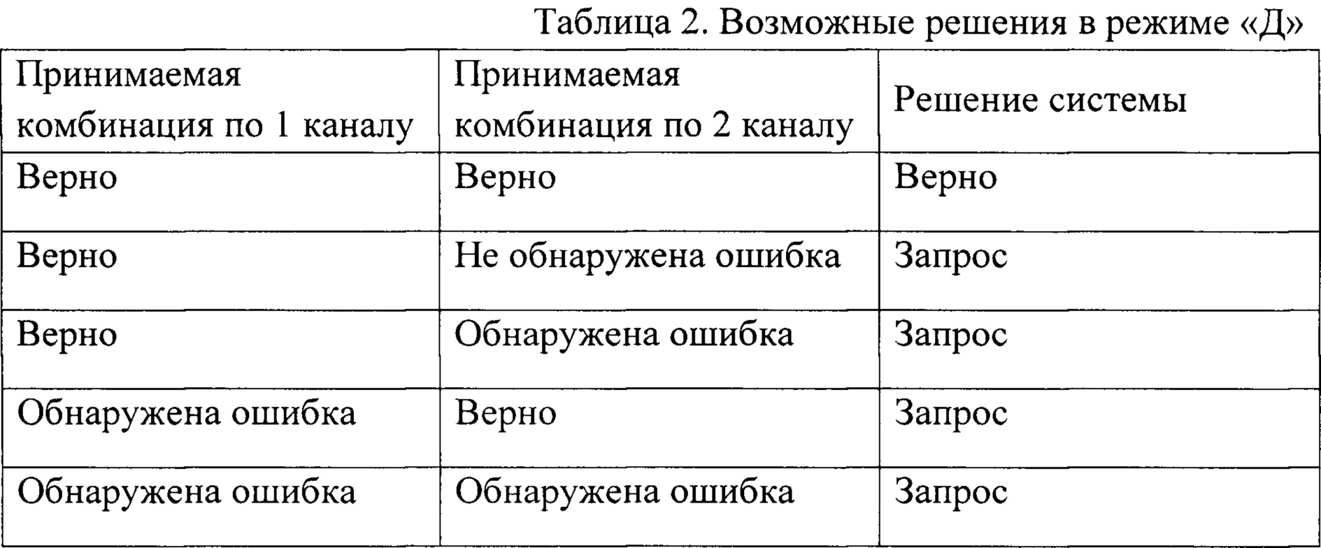
Решения системы, вырабатываемые в зависимости от принятых комбинаций, приведены в таблице 2.The system solutions developed depending on the combinations taken are shown in table 2.
При поступлении по обоим каналам неискаженных комбинаций, они выдаются получателю, как и в режиме «О». Если же по одному из каналов приходят комбинации «запрос» или с обнаруженной ошибкой, то через схемы соответственно ИЛИ-2 и ИЛИ-1 дается сигнал для блокировки приемников аппаратуры РОС и постановки системы в режим запроса. В этом случае комбинации получателю и на устройство поразрядного сравнения не выдаются.Upon receipt of undistorted combinations through both channels, they are issued to the recipient, as in the “O” mode. If, on one of the channels, “request” combinations come up or with an error detected, then a signal is given through the OR-2 and OR-1 circuits, respectively, to block the receivers of the POC equipment and put the system in query mode. In this case, combinations to the recipient and to the bitwise comparison device are not issued.
При поступлении по одному из каналов неискаженной комбинации, а по другому комбинации с необнаруженными ошибками они через накопители каналов Н, контакты переключающего устройства П1 поступают на устройство поразрядного сравнения, выполненное на элементе «И». Устройство поразрядного сравнения регистрирует несовпадение элементов, блокирует вывод этих комбинаций получателю путем подачи сигнала с выхода элемента И, контакты переключателя П2 в режиме Д, выхода ключа Кл1 на блокировку Кл2 и одновременно через логические элементы ИЛИ-1 и ИЛИ-2 подача сигнала на блокировку приемного устройства и команды на передачу сигнала «запрос».When one of the channels receives an undistorted combination, and in another combination with undetected errors, they are transmitted through the channel accumulators H, the contacts of the switching device P1 are sent to the bitwise comparison device, made on the element "I". The bitwise comparison device registers the mismatch of the elements, blocks the output of these combinations to the recipient by sending a signal from the output of the And element, contacts of the P2 switch in D mode, the output of the Cl1 key to lock Cl2, and simultaneously through the logic elements OR-1 and OR-2, the signal is transmitted to block the receiving devices and commands for transmitting the signal "request".
Только в одном случае в этом режиме получателю выдается ложная информация. Это происходит, когда по обоим каналам приняты комбинации с необнаруженными ошибками, и при условии, что ошибки в обеих комбинациях идентичны. Вероятность такого события определяется бесконечно малой величиной.Only in one case, in this mode, the recipient is given false information. This occurs when combinations with undetected errors are received on both channels, and provided that the errors in both combinations are identical. The probability of such an event is determined by an infinitesimal quantity.
Таким образом, можно сделать вывод, что режим «Д» системы обеспечивает весьма высокую достоверность принимаемой информации.Thus, we can conclude that the “D” mode of the system provides a very high reliability of the received information.

Режим «К» является комплексным, то есть в нем одновременно используются алгоритмы, описанные для двух предыдущих режимов «О» и «Д». Переключение устройства в режим «К» осуществляется переключателями П1 и П2.The “K” mode is complex, that is, it simultaneously uses the algorithms described for the two previous modes “O” and “D”. Switching the device to the "K" mode is carried out by the switches P1 and P2.
Когда в одном из приемных устройств обнаружена ошибка, сигналом от АПС данного канала блокируется Кл1 и тем самым отключается устройство поразрядного сравнения, блокируется накопитель Н данного канала, запрещая выдачу информации получателю, и одновременно через логические элементы ИЛИ-1 и ИЛИ-2 подается сигнал на блокировку приемного устройства и выдачу команды на передачу сигнала «запрос».When an error is detected in one of the receiving devices, the signal from the APS of this channel is blocked by Cl1 and thereby the bit-by-bit comparison device is turned off, the drive H of this channel is blocked, prohibiting the delivery of information to the recipient, and at the same time a signal is transmitted through the logical elements OR-1 and OR-2 blocking the receiving device and issuing a command to transmit a “request” signal.
Получателю выводится информация не только в том случае, когда по обоим каналам принимаются верные комбинации, как в режиме «Д», но и когда по одному из каналов принимаем верную информацию, а по другому каналу обнаружена ошибка.The recipient receives information not only when the correct combinations are received on both channels, as in the “D” mode, but also when the correct information is received on one of the channels, and an error is detected on the other channel.
В этом случае сигналом с выхода АПС канала, по которому принята искаженная комбинация, блокируется накопитель Н данного канала и ключ Кл1. То есть блокируется выдача искаженной информации получателю и отключается устройство поразрядного сравнения. Верная комбинация по другому каналу через накопитель Н, контакты переключателя П1 в режиме «К», через элемент ИЛИ-3, ключ Кл2 выдается получателю.In this case, the signal from the output of the APS channel, through which the distorted combination is received, blocks the drive H of this channel and the key Kl1. That is, the delivery of distorted information to the recipient is blocked and the bitwise comparison device is turned off. The correct combination is through a different channel through the drive H, the contacts of switch P1 in the "K" mode, through the element OR-3, the key Kl2 is issued to the recipient.
То есть эта программа работы предусматривает уменьшение количества посылаемых запросов, за счет незначительного увеличения вероятности 5 приема искаженных сигналов.That is, this program of work provides for a decrease in the number of requests sent, due to a slight increase in the probability 5 of receiving distorted signals.
Решения, которые принимает система, в зависимости от принятых комбинаций сведены в таблицу 3.The decisions that the system makes, depending on the combinations taken, are summarized in table 3.

Claims (1)
Priority Applications (1)
| Application Number | Priority Date | Filing Date | Title |
|---|---|---|---|
| RU2016107522U RU172100U1 (en) | 2016-03-02 | 2016-03-02 | DEVICE FOR INCREASING EFFICIENCY AND RELIABILITY OF PROCESSING CRYPTOGRAMS |
Applications Claiming Priority (1)
| Application Number | Priority Date | Filing Date | Title |
|---|---|---|---|
| RU2016107522U RU172100U1 (en) | 2016-03-02 | 2016-03-02 | DEVICE FOR INCREASING EFFICIENCY AND RELIABILITY OF PROCESSING CRYPTOGRAMS |
Publications (1)
| Publication Number | Publication Date |
|---|---|
| RU172100U1 true RU172100U1 (en) | 2017-06-28 |
Family
ID=59310267
Family Applications (1)
| Application Number | Title | Priority Date | Filing Date |
|---|---|---|---|
| RU2016107522U RU172100U1 (en) | 2016-03-02 | 2016-03-02 | DEVICE FOR INCREASING EFFICIENCY AND RELIABILITY OF PROCESSING CRYPTOGRAMS |
Country Status (1)
| Country | Link |
|---|---|
| RU (1) | RU172100U1 (en) |
Citations (6)
| Publication number | Priority date | Publication date | Assignee | Title |
|---|---|---|---|---|
| WO2002010962A1 (en) * | 2000-07-28 | 2002-02-07 | Storymail, Inc. | System, method and computer program product for device, operating system, and network transport neutral secure interactive multi-media messaging |
| RU70066U1 (en) * | 2007-10-22 | 2008-01-10 | Государственное образовательное учреждение высшего профессионального образования "Кубанский государственный технологический университет" (ГОУВПО "КубГТУ") | RELIABILITY AND INFORMATION TRANSMISSION DEVICE |
| RU70384U1 (en) * | 2007-10-16 | 2008-01-20 | Государственное образовательное учреждение высшего профессионального образования "Кубанский государственный технологический университет" (ГОУВПО "КубГТУ") | INFORMATION TRANSFER RELIABILITY DEVICE |
| RU70426U1 (en) * | 2007-10-16 | 2008-01-20 | Государственное образовательное учреждение высшего профессионального образования "Кубанский государственный технологический университет" (ГОУВПО "КубГТУ") | DEVICE FOR INCREASING INFORMATION SPEED |
| US8041961B2 (en) * | 2005-05-12 | 2011-10-18 | Hitachi, Ltd. | Storage system |
| RU2434334C1 (en) * | 2010-07-20 | 2011-11-20 | Открытое акционерное общество "Российский институт мощного радиостроения" | Method of evaluating reception integrity of multi-position differential phase shift keyed signals |
-
2016
- 2016-03-02 RU RU2016107522U patent/RU172100U1/en not_active IP Right Cessation
Patent Citations (6)
| Publication number | Priority date | Publication date | Assignee | Title |
|---|---|---|---|---|
| WO2002010962A1 (en) * | 2000-07-28 | 2002-02-07 | Storymail, Inc. | System, method and computer program product for device, operating system, and network transport neutral secure interactive multi-media messaging |
| US8041961B2 (en) * | 2005-05-12 | 2011-10-18 | Hitachi, Ltd. | Storage system |
| RU70384U1 (en) * | 2007-10-16 | 2008-01-20 | Государственное образовательное учреждение высшего профессионального образования "Кубанский государственный технологический университет" (ГОУВПО "КубГТУ") | INFORMATION TRANSFER RELIABILITY DEVICE |
| RU70426U1 (en) * | 2007-10-16 | 2008-01-20 | Государственное образовательное учреждение высшего профессионального образования "Кубанский государственный технологический университет" (ГОУВПО "КубГТУ") | DEVICE FOR INCREASING INFORMATION SPEED |
| RU70066U1 (en) * | 2007-10-22 | 2008-01-10 | Государственное образовательное учреждение высшего профессионального образования "Кубанский государственный технологический университет" (ГОУВПО "КубГТУ") | RELIABILITY AND INFORMATION TRANSMISSION DEVICE |
| RU2434334C1 (en) * | 2010-07-20 | 2011-11-20 | Открытое акционерное общество "Российский институт мощного радиостроения" | Method of evaluating reception integrity of multi-position differential phase shift keyed signals |
Similar Documents
| Publication | Publication Date | Title |
|---|---|---|
| US9363114B2 (en) | Clock-embedded vector signaling codes | |
| Bana et al. | Short packet structure for ultra-reliable machine-type communication: Tradeoff between detection and decoding | |
| CN107317644A (en) | A kind of compatible burst and the frame-synchronizing device of continuous data | |
| US7873425B2 (en) | System and method of processing compressed audio data | |
| Song et al. | Maximum sum rate of repeat-accumulate interleave-division system by fixed-point analysis | |
| US4860323A (en) | Method and device for the acquisition of synchronization bits in data transmission systems | |
| RU172100U1 (en) | DEVICE FOR INCREASING EFFICIENCY AND RELIABILITY OF PROCESSING CRYPTOGRAMS | |
| US8015316B2 (en) | Method and system for detecting messages in the presence of noise | |
| US9203561B2 (en) | Method and apparatus for burst start detection | |
| US3444516A (en) | Error correcting communication system | |
| US6279139B1 (en) | Transmission system | |
| US20060280263A1 (en) | Apparatus and method for processing input signals corresponding to the same signal source at different timings | |
| RU70426U1 (en) | DEVICE FOR INCREASING INFORMATION SPEED | |
| US3422357A (en) | Frequency shift diversity receiver with output determined by majority of inputs | |
| RU70066U1 (en) | RELIABILITY AND INFORMATION TRANSMISSION DEVICE | |
| US20050002480A1 (en) | Digital switching wireless receiver diversity and buffer diversity for enhanced reception in a wireless digital audio communication system | |
| US3270285A (en) | Information reinsertion telegraphy receivers | |
| Huang et al. | Energy-efficient communication in the presence of synchronization errors | |
| Shahi et al. | On the capacity of the slotted strongly asynchronous channel with a bursty user | |
| Wang et al. | Binary error correcting network codes | |
| RU70384U1 (en) | INFORMATION TRANSFER RELIABILITY DEVICE | |
| RU2696329C2 (en) | Device for receiving information on two parallel communication channels in a system for transmitting data with crucial feedback | |
| RU2543469C2 (en) | Device for receiving information via two parallel communication channels | |
| Ning et al. | Sequence Detection Algorithm Based on Local Error Correction in Differential Frequency Hopping System | |
| SU966923A1 (en) | Data transmission system through feedback channels |
Legal Events
| Date | Code | Title | Description |
|---|---|---|---|
| MM9K | Utility model has become invalid (non-payment of fees) |
Effective date: 20180303 |