RU168703U1 - Pyroelectric undulator - Google Patents
Pyroelectric undulator Download PDFInfo
- Publication number
- RU168703U1 RU168703U1 RU2016126061U RU2016126061U RU168703U1 RU 168703 U1 RU168703 U1 RU 168703U1 RU 2016126061 U RU2016126061 U RU 2016126061U RU 2016126061 U RU2016126061 U RU 2016126061U RU 168703 U1 RU168703 U1 RU 168703U1
- Authority
- RU
- Russia
- Prior art keywords
- pyroelectric
- undulator
- pairs
- crystals
- crystal
- Prior art date
Links
Images
Classifications
-
- G—PHYSICS
- G21—NUCLEAR PHYSICS; NUCLEAR ENGINEERING
- G21K—TECHNIQUES FOR HANDLING PARTICLES OR IONISING RADIATION NOT OTHERWISE PROVIDED FOR; IRRADIATION DEVICES; GAMMA RAY OR X-RAY MICROSCOPES
- G21K1/00—Arrangements for handling particles or ionising radiation, e.g. focusing or moderating
- G21K1/08—Deviation, concentration or focusing of the beam by electric or magnetic means
- G21K1/087—Deviation, concentration or focusing of the beam by electric or magnetic means by electrical means
Abstract
Использование: для получения электромагнитного излучения. Сущность полезной модели заключается в том, что пироэлектрический ондулятор содержит компактные модули, расположенные друг напротив друга, каждый из которых включает в себя пироэлектрический кристалл, теплопровод, элемент Пельтье и радиатор, кроме этого пироэлектрический ондулятор содержит более чем две пары компактных модулей и дополнительно включает синхронизатор питания используемых элементов Пельтье. Технический результат: обеспечение возможности генерации коллимированного когерентного электромагнитного излучения со спектром, близким к квазимонохроматичному. 1 ил.Use: to obtain electromagnetic radiation. The essence of the utility model is that the pyroelectric undulator contains compact modules located opposite each other, each of which includes a pyroelectric crystal, a heat conductor, a Peltier element and a radiator, in addition, the pyroelectric undulator contains more than two pairs of compact modules and additionally includes a synchronizer power used peltier elements. EFFECT: provision of the possibility of generating collimated coherent electromagnetic radiation with a spectrum close to quasimonochromatic. 1 ill.
Description
Полезная модель пироэлектрический ондулятор относится к технике ускорителей заряженных частиц, в частности к технике ускорительных устройств, предназначенных для получения электромагнитного излучения.A useful model of a pyroelectric undulator relates to the technique of charged particle accelerators, in particular to the technique of accelerator devices designed to produce electromagnetic radiation.
Традиционный электромагнитный ондулятор представляет собой цепочку из слабых близкорасположенных постоянных магнитов. При прохождении через эту систему, электронный пучок отклонялся слабыми магнитными полями в поперечном направлении, а траектория приобретала форму волны. Затем вдоль всей траектории движения испускается яркий и узкий пучок ондуляторного электромагнитного излучения. На таком принципе работы основан мощный электромагнитный ондулятор (US №4761584A, опубл. 02.08.1988 г.). Устройство, описанное в данном патенте, представляет стандартную магнитную систему, которая обеспечивает необходимую траекторию пучка при прохождении внутри устройства.A traditional electromagnetic undulator is a chain of weak closely spaced permanent magnets. When passing through this system, the electron beam was deflected by weak magnetic fields in the transverse direction, and the trajectory took the form of a wave. Then, a bright and narrow beam of undulator electromagnetic radiation is emitted along the entire trajectory of movement. A powerful electromagnetic undulator is based on this principle of operation (US No. 4761584A, publ. 08/02/1988). The device described in this patent represents a standard magnetic system that provides the necessary beam path when passing inside the device.
На сегодняшний день известны многие устройства и технологии, направленные на модернизацию традиционного электромагнитного ондулятора.Today, many devices and technologies are known that are aimed at modernizing the traditional electromagnetic undulator.
Одним из таковых является устройство короткопериодного мини-ондулятора (US № 20130099881, опубл. 25.04.2013 г.). В работе рассматривается возможность использования в конструкции сверхпроводящих материалов, благодаря которым, при прохождении через устройство период колебания пучка будет значительно меньше, чем на устройствах применяющих стандартные постоянные магниты. One such device is a short-period mini-undulator (US No. 20130099881, publ. 04.25.2013). The paper considers the possibility of using superconducting materials in the design, due to which, when passing through the device, the period of beam oscillation will be much less than on devices using standard permanent magnets.
Известен короткопериодный ондулятор (EP № 2745649, опубл. 25.06.2014 г.). В данном решении предлагается использование электромагнитной стоячей волны в ондуляторе для генерации электромагнитного излучения в терагерцовом диапазоне. Known short-period undulator (EP No. 2745649, publ. 06/25/2014). This solution proposes the use of an electromagnetic standing wave in an undulator to generate electromagnetic radiation in the terahertz range.
Известен также поверхностный микромеханический микромагнитный ондулятор (US № 9247630, опубл. 26.01.2016 г.). В данной работе предлагается способ получения ондулятора с коротким периодом структуры от 5 мкм до 5 мм.Also known is a surface micromechanical micromagnetic undulator (US No. 9247630, publ. 26.01.2016). In this work, we propose a method for producing an undulator with a short period of structure from 5 μm to 5 mm.
Наиболее близким по исполнению к предлагаемому изобретению является пироэлектрический дефлектор пучка заряженных частиц (RU № 156716, опубл. 10.11.2015 г.). Конструкция описываемого технического решения представляет собой два компактных модуля, расположенных друг напротив друга. Каждый из модулей состоит из пироэлектрического кристалла, элемента Пельтье, теплопровода и радиатора. Устройство предназначено для управления параметрами пучка заряженных частиц. Принцип работы прототипа основан на изменении величины и направления температурного градиента пироэлектрического кристалла, которые обуславливают генерацию сильного электрического поля, позволяющего управлять параметрами пучка заряженных частиц.The closest to the implementation of the present invention is a pyroelectric deflector of a beam of charged particles (RU No. 156716, publ. 10.11.2015,). The design of the described technical solution is two compact modules located opposite each other. Each of the modules consists of a pyroelectric crystal, a Peltier element, a heat pipe and a radiator. The device is designed to control the parameters of a beam of charged particles. The principle of operation of the prototype is based on a change in the magnitude and direction of the temperature gradient of the pyroelectric crystal, which determine the generation of a strong electric field that allows you to control the parameters of a beam of charged particles.
К общим недостаткам аналогов и прототипа следует отнести большие габариты стандартных электромагнитных ондуляторов, энергозатратность их систем питания, короткий период воздействия электрического поля на пучок заряженных частиц, ограниченный только пространством между кристаллами, а также инерционность смены полярности заряда на поверхности кристалла при смене температурной фазы.The common disadvantages of analogues and prototype include the large dimensions of standard electromagnetic undulators, the energy consumption of their power systems, the short period of exposure of an electric field to a beam of charged particles, limited only by the space between the crystals, and the inertia of the change in charge polarity on the crystal surface when changing the temperature phase.
Задачей, на решение которой направлено предлагаемое техническое решение, является создание устройства предназначенного для генерации когерентного электромагнитного излучения при извилистом движении пучка заряженных частиц в пространстве между парами пироэлектрических кристаллов.The task to which the proposed technical solution is directed is to create a device designed to generate coherent electromagnetic radiation during the meandering motion of a beam of charged particles in the space between pairs of pyroelectric crystals.
Поставленная задача решается с помощью предлагаемого пироэлектрического ондулятора, который содержит компактные модули, расположенные друг напротив друга, каждый из которых включает в себя пироэлектрический кристалл, теплопровод, элемент Пельтье и радиатор, причем пироэлектрический ондулятор содержит более чем две пары компактных модулей и дополнительно включает синхронизатор питания используемых элементов Пельтье.The problem is solved using the proposed pyroelectric undulator, which contains compact modules located opposite each other, each of which includes a pyroelectric crystal, a heat pipe, a Peltier element and a radiator, moreover, the pyroelectric undulator contains more than two pairs of compact modules and additionally includes a power synchronizer Peltier elements used.
Предлагаемое устройство отличается от пироэлектрического дефлектора пучка заряженных частиц, описанного в прототипе (RU №156716, опубл. 10.11.2015 г.), тем, что содержит большее количество пар компактных модулей, а также дополнительно включает синхронизатор полярности питания элемента Пельтье. The proposed device differs from the pyroelectric deflector of a charged particle beam described in the prototype (RU No. 156716, publ. 10.11.2015), in that it contains a larger number of pairs of compact modules, and also includes a Peltier element polarity synchronizer.
Преимущество предлагаемого изобретения заключается в возможности получения электромагнитного квазимонохроматического излучения в узком угловом диапазоне до 100 мрад, а также в энергетическом диапазоне от 1 нм до 10 мкм с помощью предлагаемого малогабаритного устройства, в котором применяются пироэлектрические кристаллы для решения поставленной задачи.The advantage of the invention lies in the possibility of obtaining electromagnetic quasimonochromatic radiation in a narrow angular range up to 100 mrad, as well as in the energy range from 1 nm to 10 μm using the proposed small-sized device in which pyroelectric crystals are used to solve the problem.
При этом не используются сложные и дорогостоящие системы генерации стоячих электромагнитных волн, как в короткопериодном ондуляторе (EP №2745649), или громоздкие магниты, как в мощном электромагнитном ондуляторе (US №4761584A). In this case, complex and expensive systems for generating standing electromagnetic waves are not used, as in a short-period undulator (EP No. 2745649), or bulky magnets, as in a powerful electromagnetic undulator (US No. 4761584A).
Технический результат заключается в генерации коллимированного когерентного электромагнитного излучения со спектром, близким к квазимонохроматичному. Это достигается посредством извилистого движения, близкого к синусоиде, ультрарелятивистского пучка заряженных частиц в электрическом поле, генерирующемся в промежутке между пироэлектрическими кристаллами при изменении их температуры.The technical result consists in the generation of collimated coherent electromagnetic radiation with a spectrum close to quasimonochromatic. This is achieved by means of a tortuous motion close to a sinusoid, an ultrarelativistic beam of charged particles in an electric field generated in the gap between pyroelectric crystals with a change in their temperature.
Полезная модель поясняется чертежом.The utility model is illustrated in the drawing.
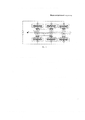
Фиг. 1 - Общий вид полезной модели.FIG. 1 - General view of the utility model.
Устройство состоит из более чем двух пар модулей. Модули расположены друг напротив друга. В состав каждого модуля входит: пироэлектрический кристалл - 1, теплопровод - 2, элемент Пельтье – 3, радиатор – 4 и синхронизатор - 5.The device consists of more than two pairs of modules. The modules are located opposite each other. Each module includes: pyroelectric crystal - 1, heat conduit - 2, Peltier element - 3, radiator - 4 and synchronizer - 5.
Пироэлектрический кристалл 1, такой как, например LiNbO3 (ниобат лития), изготовлен в форме цилиндра. Характерный размер пироэлектрического кристалла 1 – 1 см. Теплопровод 2 представляет собой пластину, например, из меди или дюралюминия, прикрепленную с помощью электропроводящего клея между пироэлектрическим кристаллом 1 и элементом Пельтье 3. Толщина теплопровода 2 не должна превышать 1.5 - 2 мм, а площадь его поверхности должна быть больше, чем площадь поверхности элемента Пельтье 3. Это требуется для оптимального терморегулирования пироэлектрического кристалла 1. Также теплопровод 2 должен быть обязательно заземлен. Элемент Пельтье 3 – устройство, позволяющее изменять температуру пироэлектрического кристалла 1. Элемент Пельтье 3 соединен с радиатором 4 с помощью теплопроводящего клея. Радиатор 4 выполнен из меди или алюминия, а его геометрия зависит от конструкции устройства, в котором подразумевается его применение. Радиатор 4 предназначен для отвода лишнего тепла от элемента Пельтье 3, тем самым обеспечивая нормальный температурный режим работы устройства. Синхронизатор 5 - управляющая электронная схема, которая обеспечивает питание всех элементов Пельтье 3 и тем самым поддерживает необходимый режим изменения температуры пироэлектрического кристалла 1 в каждом из модулей устройства. The
Для обеспечения работы устройства минимальное количество пар модулей должно составлять не менее двух, а максимальное количество пар не ограничено и определяется конкретной спецификой поставленной задачи. Все пироэлектрические кристаллы 1, из которых состоит устройство, должны быть одинакового размера и напряжение, подаваемое на элемент Пельтье 3, должно быть одинаково по модулю для всего устройства. Допускается, что отличаться по размеру и величине подаваемого напряжения могут только пироэлектрические кристаллы 1, составляющие первую пару модулей, расположенную на входе устройства, так как перед этой парой пучок движется по прямолинейной траектории и осуществляет первичное отклонение пучка заряженных частиц. Остальные пары пироэлектрических кристаллов 1 необходимы для поддержания извилистой траектории в определенном периоде. To ensure the operation of the device, the minimum number of pairs of modules must be at least two, and the maximum number of pairs is not limited and is determined by the specific nature of the task. All
Принцип работы полезной модели основан на периодическом искривлении траектории пучка ускоренных заряженных частиц в электрическом поле, которое генерируется двумя и более парами пироэлектрических кристаллов при изменении их температуры. Работает предлагаемое устройство в условиях вакуума при давлении остаточного газа 10-5 Торр и ниже. В общем случае, на каждый элемент Пельтье 3 пары модулей подается напряжение равной величины и противоположной полярности. На рабочей поверхности каждого пироэлектрического кристалла 1 индуцируется электрический заряд. Полярность заряда зависит от ориентации вектора спонтанной поляризации пироэлектрического кристалла 1 и полярности подаваемого напряжения. Для работы устройства важно выполнение двух условий. Первое заключается в том, что поверхности двух пироэлектрических кристаллов 1 в каждой паре должны быть заряжены разноименно, чтобы создавать поперечное отклоняющее электрическое поле. Второе - поля, создаваемые двумя соседними парами модулей в промежутке между пироэлектрическими кристаллами 1, должны иметь противоположную направленность по отношению друг к другу, чтобы обеспечить необходимую извилистую траекторию пучка, близкую к синусоиде, при которой происходит генерация электромагнитного излучения. При этом пучок заряженных частиц входит прямолинейно в промежуток между пироэлектрическими кристаллами 1 первой пары - h2 (Фиг.1) и начинает отклоняться в сторону относительно первоначальной траектории (противоположно заряженной поверхности пироэлектрического кристалла 1, по отношению к полярности заряда пучка). В промежутке между пироэлектрическими кристаллами 1 первой и второй пары пучок заряженных частиц усиливает свое отклонение, а затем под действием электрического поля второй пары, отклоняется в противоположную сторону. Далее, подобное извилистое, близкое к синусоиде, движение пучка продолжается и между последующими парами и в промежутках между ними.The principle of operation of the utility model is based on the periodic curvature of the trajectory of a beam of accelerated charged particles in an electric field, which is generated by two or more pairs of pyroelectric crystals with a change in their temperature. The proposed device operates in vacuum at a residual gas pressure of 10 -5 Torr and below. In general, a voltage of equal magnitude and opposite polarity is applied to each Peltier element of 3 pairs of modules. An electric charge is induced on the working surface of each
Для получения требуемых характеристик электромагнитного излучения необходимо обеспечить стабильное извилистое движение пучка заряженных частиц внутри предлагаемого пироэлектрического ондулятора при этом, не касаясь поверхности пироэлектрических кристаллов 1 пучком заряженных частиц. Возможны два варианта обеспечения стабильного извилистого движения пучка заряженных частиц. В первом варианте, подразумевающем равенство размеров всех пироэлектрических кристаллов 1, в предлагаемом пироэлектрическом ондуляторе необходимо, чтобы напряжение, подаваемое на элементы Пельтье 3 первой пары, было в два раза меньше, чем напряжение, подаваемое на элементы Пельтье 3 последующих пар. Во втором варианте, когда обеспечено равенство напряжения, подаваемого на все элементы Пельтье 3 устройства, необходимо, чтобы рабочая поверхность пироэлектрических кристаллов 1 в первой паре была в два раза меньше, чем поверхность пироэлектрических кристаллов 1 в других парах. To obtain the required characteristics of electromagnetic radiation, it is necessary to ensure stable twisty movement of the beam of charged particles inside the proposed pyroelectric undulator while not touching the surface of the
Если все же касание пучка при продолжительной работе устройства неизбежно или дальнейшее изменение температуры в определенную сторону не представляется возможным, полярность напряжения на всех элементах Пельтье 3 меняется при помощи синхронизатора 5, предусмотренного в предлагаемой полезной модели. При этом геометрия генерации фотонов остается неизменной. При такой извилистой траектории ультрарелятивистского пучка заряженных частиц, близкой к синусоиде, происходит излучение фотонов в узкий конус вдоль оси движения пучка. Далее, после прохождения через пироэлектрический ондулятор пучок может отклоняться в сторону с помощью магнитной оптики, а распространяющийся поток фотонов использоваться в зависимости от постановки задачи.If, nevertheless, touching the beam during continuous operation of the device is unavoidable or further temperature change to a certain direction is not possible, the polarity of the voltage across all Peltier
В качестве примера осуществления работы пироэлектрического ондулятора рассматривается распространяющийся в устройстве пучок электронов с энергией 10 ГэВ. Пироэлектрический ондулятор имеет период 1 см - h1 (Фиг.1) (расстояние между двумя идентичными точками соседних пар модулей). Диаметр пироэлектрического кристалла 1, такого как LiTaO3, равен 8 мм. Высота пироэлектрического кристалла 1 составляет 10 мм. Промежуток между кристаллами 1 в паре равен 8 мм – h2 (Фиг.1), а промежуток между кристаллами 1 соседних пар - 8 мм – h3 (Фиг.1). Всего в устройстве 100 пар модулей. Теплопровод 2 представляет собой квадратную пластину толщиной 0.5 мм и длиной 12 мм, изготовленную из меди и прикрепленную к поверхности пироэлектрического кристалла 1 с помощью электропроводящего клея. Элемент Пельтье 3 имеет один ярус, размер пластины составляет 12*12 мм. Радиатор 4 представляет собой параллелепипед с размерами 70*70*70 мм, изготовленный из дюралюминия Д16Т и прикрепленный к поверхности элемента Пельтье с помощью теплопроводящего клея. Для получения электромагнитного излучения с частотой 1 эВ или длиной волны 1 нм (диапазон мягкого рентгеновского излучения) вдоль оси движения электронного пучка скорость изменения температуры каждого кристалла составляла около 1.3°С/сек. При этой скорости изменения температуры пучок отклоняется на 0.025° от первоначальной траектории в каждой паре, что приводит к генерации электромагнитного излучения вдоль траектории движения в узком конусе с углом раствора 0.3. Для обеспечения такого режима работы устройства на все элементы Пельтье 3 (кроме элементов Пельтье 3 первой пары модулей) подавалась электрическая мощность 10 Вт. А для поддержания стабильного извилистого движения пучка заряженных частиц внутри пироэлектрического ондулятора, не касаясь поверхности пироэлектрических кристаллов 1, выполнялось условие равенства размеров всех пироэлектрических кристаллов 1, при этом подаваемое напряжение было снижено в два раза и составляло 5 Вт. Синхронное изменение температуры пироэлектрических кристаллов 1 обеспечивалось синхронизатором 5, позволяющим изменять значение и полярность напряжения, подаваемого на элементы Пельтье 3.As an example of the operation of the pyroelectric undulator, an electron beam propagating in the device with an energy of 10 GeV is considered. The pyroelectric undulator has a period of 1 cm - h 1 (Figure 1) (the distance between two identical points of adjacent pairs of modules). The diameter of the
Исходя из всего вышеописанного применение предлагаемого устройства возможно в источниках синхротронного излучения, ускорителях заряженных частиц различного назначения (исследование различных структур, радиационная терапия, диагностика) для получения ондуляторного излучения. Дополнительно предлагаемое устройство, может применяться для управления пучком заряженных частиц.Based on the foregoing, the use of the proposed device is possible in sources of synchrotron radiation, accelerators of charged particles for various purposes (study of various structures, radiation therapy, diagnostics) to obtain undulator radiation. Additionally, the proposed device can be used to control a beam of charged particles.
Claims (1)
Priority Applications (1)
| Application Number | Priority Date | Filing Date | Title |
|---|---|---|---|
| RU2016126061U RU168703U1 (en) | 2016-06-29 | 2016-06-29 | Pyroelectric undulator |
Applications Claiming Priority (1)
| Application Number | Priority Date | Filing Date | Title |
|---|---|---|---|
| RU2016126061U RU168703U1 (en) | 2016-06-29 | 2016-06-29 | Pyroelectric undulator |
Publications (1)
| Publication Number | Publication Date |
|---|---|
| RU168703U1 true RU168703U1 (en) | 2017-02-15 |
Family
ID=58450623
Family Applications (1)
| Application Number | Title | Priority Date | Filing Date |
|---|---|---|---|
| RU2016126061U RU168703U1 (en) | 2016-06-29 | 2016-06-29 | Pyroelectric undulator |
Country Status (1)
| Country | Link |
|---|---|
| RU (1) | RU168703U1 (en) |
Cited By (1)
| Publication number | Priority date | Publication date | Assignee | Title |
|---|---|---|---|---|
| RU184178U1 (en) * | 2018-03-12 | 2018-10-18 | Дмитрий Николаевич Харитонов | SUPERCONDUCTOR EMISSION ONDULATOR |
Citations (5)
| Publication number | Priority date | Publication date | Assignee | Title |
|---|---|---|---|---|
| US20080231215A1 (en) * | 2004-01-23 | 2008-09-25 | Hideo Kitamura | Undulator |
| RU2462009C1 (en) * | 2011-06-08 | 2012-09-20 | Мурадин Абубекирович Кумахов | Method of changing direction of beam of accelerated charged particles, device for realising said method, electromagnetic radiation source, linear and cyclic charged particle accelerators, collider and means of producing magnetic field generated by current of accelerated charged particles |
| US20130099881A1 (en) * | 2011-10-25 | 2013-04-25 | Alex K. Deyhim | Short period super-mini undulator |
| WO2013112226A2 (en) * | 2011-11-11 | 2013-08-01 | The Regents Of The University Of California | Surface-micromachined micro-magnetic undulator |
| RU156716U1 (en) * | 2015-04-07 | 2015-11-10 | Федеральное государственное автономное образовательное учреждение высшего профессионального образования "Белгородский государственный национальный исследовательский университет" (НИУ "БелГУ") | Pyroelectric deflector of a bunch of charged particles |
-
2016
- 2016-06-29 RU RU2016126061U patent/RU168703U1/en active
Patent Citations (5)
| Publication number | Priority date | Publication date | Assignee | Title |
|---|---|---|---|---|
| US20080231215A1 (en) * | 2004-01-23 | 2008-09-25 | Hideo Kitamura | Undulator |
| RU2462009C1 (en) * | 2011-06-08 | 2012-09-20 | Мурадин Абубекирович Кумахов | Method of changing direction of beam of accelerated charged particles, device for realising said method, electromagnetic radiation source, linear and cyclic charged particle accelerators, collider and means of producing magnetic field generated by current of accelerated charged particles |
| US20130099881A1 (en) * | 2011-10-25 | 2013-04-25 | Alex K. Deyhim | Short period super-mini undulator |
| WO2013112226A2 (en) * | 2011-11-11 | 2013-08-01 | The Regents Of The University Of California | Surface-micromachined micro-magnetic undulator |
| RU156716U1 (en) * | 2015-04-07 | 2015-11-10 | Федеральное государственное автономное образовательное учреждение высшего профессионального образования "Белгородский государственный национальный исследовательский университет" (НИУ "БелГУ") | Pyroelectric deflector of a bunch of charged particles |
Cited By (1)
| Publication number | Priority date | Publication date | Assignee | Title |
|---|---|---|---|---|
| RU184178U1 (en) * | 2018-03-12 | 2018-10-18 | Дмитрий Николаевич Харитонов | SUPERCONDUCTOR EMISSION ONDULATOR |
Similar Documents
| Publication | Publication Date | Title |
|---|---|---|
| US20190302625A1 (en) | Lithographic method | |
| Ruf et al. | Pair production in laser fields oscillating in space and time | |
| US20050279947A1 (en) | Acceleration of charged particles using spatially and temporally shaped electromagnetic radiation | |
| Esirkepov et al. | Boosted high-harmonics pulse from a double-sided relativistic mirror | |
| WO2016023740A2 (en) | Radiation source | |
| Hebling et al. | Optical manipulation of relativistic electron beams using THz pulses | |
| Kopiev et al. | Jet noise control using the dielectric barrier discharge plasma actuators | |
| US20140314114A1 (en) | Short Period Undulator | |
| JP2017537343A (en) | Radiation beam equipment | |
| RU168703U1 (en) | Pyroelectric undulator | |
| Ohsawa | Production of highly relativistic ions and electrons by quasi-perpendicular magnetosonic shock waves | |
| Sharma et al. | Terahertz-driven wakefield electron acceleration | |
| Korobkin et al. | Concept of generation of extremely compressed high-energy electron bunches in several interfering intense laser pulses with tilted amplitude fronts | |
| Tsintsadze | Certain relativistic effects due to strong electromagnetic fields in plasmas | |
| Yu et al. | Betatron-like resonance in ultra-intense laser mass-limited foil interaction | |
| Lei et al. | Flexible x-ray source with tunable polarization and orbital angular momentum from Hermite-Gaussian laser modes driven plasma channel wakefield | |
| CN115275754A (en) | Free electron laser and micro undulator | |
| US10736205B2 (en) | Electron beam transport system | |
| Nijhof | Towards X-ray generation by ICS using ultracold electron bunches | |
| RU175484U1 (en) | Pyroelectric quadrupole lens | |
| Nakajima et al. | Very Compact Linear Colliders Comprising Seamless Multistage Laser-Plasma Accelerators | |
| Zhang et al. | Generation of polarization controllable strong THz source from air plasma excited by three-color laser field | |
| JP4564385B2 (en) | Synchrotron radiation generator | |
| Hillenbrand | Study of plasma-based acceleration for high energy physics and other applications | |
| Jain et al. | Effect of Laser Pulse Profile on Energy of the Accelerated Ions in the Light Sail Regime |