RU166323U1 - REACTOR FOR SYNTHESIS OF NANOSTRUCTURES - Google Patents
REACTOR FOR SYNTHESIS OF NANOSTRUCTURES Download PDFInfo
- Publication number
- RU166323U1 RU166323U1 RU2015155748/02U RU2015155748U RU166323U1 RU 166323 U1 RU166323 U1 RU 166323U1 RU 2015155748/02 U RU2015155748/02 U RU 2015155748/02U RU 2015155748 U RU2015155748 U RU 2015155748U RU 166323 U1 RU166323 U1 RU 166323U1
- Authority
- RU
- Russia
- Prior art keywords
- capillary
- unit
- control unit
- oil bath
- thermostatic control
- Prior art date
Links
- 239000002086 nanomaterial Substances 0.000 title claims abstract description 35
- 230000015572 biosynthetic process Effects 0.000 title description 19
- 238000003786 synthesis reaction Methods 0.000 title description 17
- 239000002243 precursor Substances 0.000 claims abstract description 39
- 239000012530 fluid Substances 0.000 claims abstract description 10
- 230000005415 magnetization Effects 0.000 claims abstract description 8
- 239000000463 material Substances 0.000 claims abstract description 8
- 229920001343 polytetrafluoroethylene Polymers 0.000 claims abstract description 8
- 239000004810 polytetrafluoroethylene Substances 0.000 claims abstract description 8
- 230000006911 nucleation Effects 0.000 claims abstract description 6
- 238000010899 nucleation Methods 0.000 claims abstract description 6
- -1 polytetrafluoroethylene Polymers 0.000 claims abstract description 5
- 230000002194 synthesizing effect Effects 0.000 claims abstract 2
- 239000002105 nanoparticle Substances 0.000 description 17
- 239000002073 nanorod Substances 0.000 description 12
- 230000011218 segmentation Effects 0.000 description 6
- 239000012159 carrier gas Substances 0.000 description 5
- 239000000696 magnetic material Substances 0.000 description 4
- 229920001296 polysiloxane Polymers 0.000 description 4
- 238000009434 installation Methods 0.000 description 3
- 238000004519 manufacturing process Methods 0.000 description 3
- 230000000903 blocking effect Effects 0.000 description 2
- 238000011109 contamination Methods 0.000 description 2
- 230000006698 induction Effects 0.000 description 2
- NOESYZHRGYRDHS-UHFFFAOYSA-N insulin Chemical compound N1C(=O)C(NC(=O)C(CCC(N)=O)NC(=O)C(CCC(O)=O)NC(=O)C(C(C)C)NC(=O)C(NC(=O)CN)C(C)CC)CSSCC(C(NC(CO)C(=O)NC(CC(C)C)C(=O)NC(CC=2C=CC(O)=CC=2)C(=O)NC(CCC(N)=O)C(=O)NC(CC(C)C)C(=O)NC(CCC(O)=O)C(=O)NC(CC(N)=O)C(=O)NC(CC=2C=CC(O)=CC=2)C(=O)NC(CSSCC(NC(=O)C(C(C)C)NC(=O)C(CC(C)C)NC(=O)C(CC=2C=CC(O)=CC=2)NC(=O)C(CC(C)C)NC(=O)C(C)NC(=O)C(CCC(O)=O)NC(=O)C(C(C)C)NC(=O)C(CC(C)C)NC(=O)C(CC=2NC=NC=2)NC(=O)C(CO)NC(=O)CNC2=O)C(=O)NCC(=O)NC(CCC(O)=O)C(=O)NC(CCCNC(N)=N)C(=O)NCC(=O)NC(CC=3C=CC=CC=3)C(=O)NC(CC=3C=CC=CC=3)C(=O)NC(CC=3C=CC(O)=CC=3)C(=O)NC(C(C)O)C(=O)N3C(CCC3)C(=O)NC(CCCCN)C(=O)NC(C)C(O)=O)C(=O)NC(CC(N)=O)C(O)=O)=O)NC(=O)C(C(C)CC)NC(=O)C(CO)NC(=O)C(C(C)O)NC(=O)C1CSSCC2NC(=O)C(CC(C)C)NC(=O)C(NC(=O)C(CCC(N)=O)NC(=O)C(CC(N)=O)NC(=O)C(NC(=O)C(N)CC=1C=CC=CC=1)C(C)C)CC1=CN=CN1 NOESYZHRGYRDHS-UHFFFAOYSA-N 0.000 description 2
- 239000002070 nanowire Substances 0.000 description 2
- 102000004877 Insulin Human genes 0.000 description 1
- 108090001061 Insulin Proteins 0.000 description 1
- 239000004809 Teflon Substances 0.000 description 1
- 229920006362 Teflon® Polymers 0.000 description 1
- 229910052782 aluminium Inorganic materials 0.000 description 1
- XAGFODPZIPBFFR-UHFFFAOYSA-N aluminium Chemical compound [Al] XAGFODPZIPBFFR-UHFFFAOYSA-N 0.000 description 1
- 238000004590 computer program Methods 0.000 description 1
- 238000010586 diagram Methods 0.000 description 1
- 239000003814 drug Substances 0.000 description 1
- 238000005516 engineering process Methods 0.000 description 1
- 238000004880 explosion Methods 0.000 description 1
- 239000007789 gas Substances 0.000 description 1
- 238000001027 hydrothermal synthesis Methods 0.000 description 1
- 229940125396 insulin Drugs 0.000 description 1
- 238000002032 lab-on-a-chip Methods 0.000 description 1
- 210000004072 lung Anatomy 0.000 description 1
- 239000008204 material by function Substances 0.000 description 1
- 229910052751 metal Inorganic materials 0.000 description 1
- 239000002184 metal Substances 0.000 description 1
- 238000000034 method Methods 0.000 description 1
- 239000002159 nanocrystal Substances 0.000 description 1
- 239000002071 nanotube Substances 0.000 description 1
- 229910001172 neodymium magnet Inorganic materials 0.000 description 1
- QQONPFPTGQHPMA-UHFFFAOYSA-N propylene Natural products CC=C QQONPFPTGQHPMA-UHFFFAOYSA-N 0.000 description 1
- 125000004805 propylene group Chemical group [H]C([H])([H])C([H])([*:1])C([H])([H])[*:2] 0.000 description 1
- 238000005070 sampling Methods 0.000 description 1
Images
Classifications
-
- B—PERFORMING OPERATIONS; TRANSPORTING
- B22—CASTING; POWDER METALLURGY
- B22F—WORKING METALLIC POWDER; MANUFACTURE OF ARTICLES FROM METALLIC POWDER; MAKING METALLIC POWDER; APPARATUS OR DEVICES SPECIALLY ADAPTED FOR METALLIC POWDER
- B22F9/00—Making metallic powder or suspensions thereof
-
- B—PERFORMING OPERATIONS; TRANSPORTING
- B82—NANOTECHNOLOGY
- B82B—NANOSTRUCTURES FORMED BY MANIPULATION OF INDIVIDUAL ATOMS, MOLECULES, OR LIMITED COLLECTIONS OF ATOMS OR MOLECULES AS DISCRETE UNITS; MANUFACTURE OR TREATMENT THEREOF
- B82B3/00—Manufacture or treatment of nanostructures by manipulation of individual atoms or molecules, or limited collections of atoms or molecules as discrete units
-
- B—PERFORMING OPERATIONS; TRANSPORTING
- B82—NANOTECHNOLOGY
- B82Y—SPECIFIC USES OR APPLICATIONS OF NANOSTRUCTURES; MEASUREMENT OR ANALYSIS OF NANOSTRUCTURES; MANUFACTURE OR TREATMENT OF NANOSTRUCTURES
- B82Y40/00—Manufacture or treatment of nanostructures
Landscapes
- Engineering & Computer Science (AREA)
- Chemical & Material Sciences (AREA)
- Nanotechnology (AREA)
- Crystallography & Structural Chemistry (AREA)
- Manufacturing & Machinery (AREA)
- Physics & Mathematics (AREA)
- Condensed Matter Physics & Semiconductors (AREA)
- General Physics & Mathematics (AREA)
- Physical Or Chemical Processes And Apparatus (AREA)
Abstract
Реактор для синтеза наноструктур, содержащий блок дозирования, блок смешивания и сегментирования, первый и второй блоки термостатирования для нуклеации и роста и блок отбора наноструктур, соединенные с каналом движения материалов последовательно в указанном порядке, при этом блок дозирования состоит из двух насосов для подачи каждого из двух прекурсоров и насоса для подачи жидкости - носителя, выходы которых через трубки соединены с входами блока смешивания и сегментирования, выполненного в виде смесителя - тройника, выход которого соединен с политетрафторэтиленовым капилляром, часть которого размещена в масляной бане первого блока термостатирования, другая часть капилляра сформирована в спираль и размещена в масляной бане второго блока термостатирования, а выходящее из него окончание капилляра связано с блоком отбора синтезированных наноструктур, отличающийся тем, что в масляной бане второго блока термостатирования размещен постоянный магнит с аксиальной намагниченностью в виде полого цилиндра, при этом каждый из витков спирали капилляра проходит сквозь полый цилиндр постоянного магнита, направление силовых линий магнитного поля которого совпадает с направлением движения по капилляру.A reactor for synthesizing nanostructures, comprising a metering unit, a mixing and segmenting unit, a first and second temperature control unit for nucleation and growth, and a nanostructure selection unit connected to the material flow channel in series in this order, while the metering unit consists of two pumps for supplying each two precursors and a pump for supplying a carrier fluid, the outlets of which through tubes are connected to the inputs of the mixing and segmenting unit, made in the form of a mixer - tee, the output of which is inen with a polytetrafluoroethylene capillary, part of which is placed in the oil bath of the first thermostatic control unit, another part of the capillary is formed into a spiral and placed in the oil bath of the second thermostatic control unit, and the end of the capillary emerging from it is connected to the selection block of synthesized nanostructures, characterized in that in the oil bath The second thermostatic control unit contains a permanent magnet with axial magnetization in the form of a hollow cylinder, with each of the turns of the capillary spiral passing through the hollow the cylinders of the permanent magnet, the direction of magnetic field lines of which coincides with the direction of movement of the capillary.
Description
Полезная модель относится к области нанотехнологий и предназначена для проведения автоматизированного синтеза наноструктур, которые могут быть использованы в биологии, медицине, гибкой электронике, криптозащите, фоточувствительных элементах, солнечной энергетике.The utility model relates to the field of nanotechnology and is intended for the automated synthesis of nanostructures that can be used in biology, medicine, flexible electronics, cryptographic protection, photosensitive elements, and solar energy.
Известен реактор для синтеза наночастиц (заявка WO №2014153266 «Continuous flow reactor for the synthesis of nanoparticles», МПК B22F 9/16, опубл. 25.09.2014), который содержит блок дозирования прекурсоров и газа-носителя, блок смешивания и сегментирования потока прекурсоров газом-носителем, первой блок термостатирования прекурсоров, второй блок термостатирования прекурсоров и блок отбора наночастиц, связанные последовательно каналами для движения материалов.Known reactor for the synthesis of nanoparticles (application WO No. 2014153266 "Continuous flow reactor for the synthesis of nanoparticles", IPC
В таком реакторе блок дозирования прекурсоров и газа-носителя состоит из насосов, выходы которых связаны с трубками, по которым происходит перемещение дозированных прекурсоров и газа-носителя в блок смешивания и сегментирования потока прекурсоров. Блок смешивания и сегментирования потока прекурсоров состоит из узла смешивания представляющего собой T или Y-образное соединение каналов и узла сегментирования, представляющего собой T-образное соединение каналов. Выходы насосов прекурсоров связаны с входами узла смешивания, выход которого связан с одним из входов узла сегментирования. Второй вход узла сегментирования связан с выходом насоса газа-носителя, а выход узла сегментирования связан с капилляром, по которому сегментированный поток смешанных прекурсоров поступает последовательно в первый и второй блоки термостатирования, которые организованы в виде масляной бани, путем размещения капилляра с сегментированным потоком смешанных прекурсоров в масляные бани каждого из блоков. Капилляр размещенный в масленой бане второго блока термостатирования формируется в виде спирали. В блоке отбора происходит отбор наночастиц в емкости хранения.In such a reactor, the dosing unit for the precursors and carrier gas consists of pumps, the outputs of which are connected to the tubes through which the metered precursors and carrier gas are transferred to the mixing and segmenting unit of the precursor stream. The unit for mixing and segmenting the precursor stream consists of a mixing unit representing a T or Y-shaped connection of channels and a segmenting unit representing a T-shaped connection of channels. The outputs of the precursor pumps are connected to the inputs of the mixing unit, the output of which is connected to one of the inputs of the segmentation unit. The second input of the segmentation unit is connected to the output of the carrier gas pump, and the output of the segmentation unit is connected to the capillary, through which the segmented stream of mixed precursors flows sequentially into the first and second temperature control units, which are organized in the form of an oil bath, by placing a capillary with a segmented stream of mixed precursors into the oil baths of each block. The capillary placed in the oil bath of the second thermostatic control unit is formed in the form of a spiral. In the selection unit, the selection of nanoparticles in the storage tank.
Такое техническое решение реактора позволяет получать наноструктуры только в виде наночастиц, при этом продолжительность работы реактора ограничена во времени, так как поток смешанных прекурсоров сегментируется газом, что приводит к тому, что при прохождении потока смешанных и сегментированных прекурсоров всегда присутствует их контакт со стенками капилляра, это приводит к загрязнению внутренних стенок капилляров и блокировке капилляра.Such a technical solution of the reactor allows one to obtain nanostructures only in the form of nanoparticles, while the duration of the reactor is limited in time, since the flow of mixed precursors is segmented by gas, which leads to the fact that when the flow of mixed and segmented precursors is always present, they come into contact with the walls of the capillary, this leads to contamination of the inner walls of the capillaries and blocking of the capillary.
Известна установка для синтеза одномерных наноструктур (наностержней) (статья Wang J. Et al. Magnetic-Field-Induced Growth of Single-Crystalline Fe3O4 Nanowires // Advanced Materials. - 2004. - T. 16. - №. 2. - C. 137-140; статья He Z. et al. Magnetic-field-induced phase-selective synthesis of ferrosulfide microrods by a hydrothermal process: Microstructure control and magnetic properties // Advanced Functional Materials. - 2006. - T. 16. - №. 8. - C. 1105-1111), содержащая печь, в которую помещают автоклав, в нем размещена тефлоновая емкость с предварительно смешанными прекурсорами, причем эта емкость размещена внутри постоянного магнита, выполненного в форме полого цилиндра. При проведении синтеза с определенными режимами работы печи и автоклава происходит рост анизотропных структур наностержней в присутствии магнитного поля. Для этого используются магниты с магнитной индукцией 0,15 Тл, 0,25 Тл и 0,35 Тл.A known installation for the synthesis of one-dimensional nanostructures (nanorods) (article Wang J. Et al. Magnetic-Field-Induced Growth of Single-Crystalline Fe 3 O 4 Nanowires // Advanced Materials. - 2004. - T. 16. - No. 2. - C. 137-140; paper He Z. et al. Magnetic-field-induced phase-selective synthesis of ferrosulfide microrods by a hydrothermal process: Microstructure control and magnetic properties // Advanced Functional Materials. - 2006.- T. 16. - No. 8. - C. 1105-1111), containing a furnace in which an autoclave is placed, a Teflon container with pre-mixed precursors is placed in it, and this container is placed inside a permanent magnet made in the form of a hollow cylinder. During synthesis with certain operating modes of the furnace and autoclave, anisotropic structures of nanorods grow in the presence of a magnetic field. For this, magnets with magnetic induction of 0.15 T, 0.25 T and 0.35 T are used.
Такая установка не позволяет наладить поточное массовое производство, так как ее техническое решение ограничивает объемы исходных прекурсоров и соответственно объемы получаемых растворов содержащих наностержни. Кроме того, проведение синтеза с использованием такой установки характеризуется повышенной опасностью, так как при резком изменении режима синтеза возможен взрыв автоклава.Such an installation does not allow to establish mass-flow production, since its technical solution limits the volumes of the initial precursors and, accordingly, the volumes of the resulting solutions containing nanorods. In addition, the synthesis using such a setup is characterized by increased danger, since an autoclave explosion is possible with a sharp change in the synthesis mode.
Наиболее близким решением к совокупности существенных признаков к заявляемой полезной модели является реактор для синтеза наночастиц (статья Nightingale A.M. et al. A stable droplet reactor for high temperature nanocrystal synthesis // Lab on a Chip. - 2011. - T. 11. - №. 7. - C. 1221-1227.), который содержит блок дозирования прекурсоров и жидкости-носителя, блок смешивания и сегментирования потока прекурсоров жидкостью-носителем, первой блок термостатирования прекурсоров, второй блок термостатирования прекурсоров и блок отбора наночастиц, последовательно связанные каналами движения материалов. Блок дозирования состоит из двух насосов для подачи прекурсоров и насоса для подачи жидкости -носителя, выходы которых через трубки соединены с входами блока смешивания и сегментирования, выполненного в виде смесителя -тройника, выход которого соединен с политетрафторэтиленовым капилляром, часть которого размещена в масляной бане первого блока термостатирования, далее капилляр сформирован в спираль и размещен в масляной бане второго блока термостатирования, а выходящее из него окончание капилляра связано с блоком отбора синтезированных наноструктур. Разделение на два блока термостатирования обусловлены процессом синтеза, в первом блоке происходит нуклеация (зародышеобразование) при более высокой температуре, а во втором блоке термостатирования происходит рост наночастиц из зародышей при более низкой температуре. В блоке отбора происходит отбор наночастиц в емкости хранения. Использование жидкости-носителя для сегментирования потока смешанных прекурсоров приводит к отсутствию их контакта со стенками капилляра, что исключает загрязнение внутренних стенок капилляров и блокировку капилляра.The closest solution to the set of essential features for the claimed utility model is a reactor for the synthesis of nanoparticles (article Nightingale AM et al. A stable droplet reactor for high temperature nanocrystal synthesis // Lab on a Chip. - 2011. - T. 11. - No. 7. - C. 1221-1227.), Which contains a unit for dosing precursors and carrier fluid, a unit for mixing and segmenting the precursor stream with carrier fluid, a first thermostatting unit for the precursors, a second unit for thermostating the precursors and a unit for selecting nanoparticles connected in series with the channels of movement of materials . The dosing unit consists of two pumps for supplying precursors and a pump for supplying carrier fluid, the outlets of which are connected through the tubes to the inputs of the mixing and segmenting unit, made in the form of a tee mixer, the outlet of which is connected to a polytetrafluoroethylene capillary, part of which is located in the first oil bath thermostatic control unit, then the capillary is formed into a spiral and placed in the oil bath of the second thermostatic control unit, and the end of the capillary emerging from it is connected with the selection unit is synthesized s nanostructures. The division into two thermostatic control units is determined by the synthesis process, in the first unit nucleation (nucleation) occurs at a higher temperature, and in the second thermostatic control unit, nanoparticles from the nucleus grow at a lower temperature. In the selection unit, the selection of nanoparticles in the storage tank. The use of a carrier fluid for segmenting the flow of mixed precursors leads to the absence of their contact with the walls of the capillary, which eliminates contamination of the inner walls of the capillaries and blocking of the capillary.
Однако техническое решение такой установки обеспечивает получение наночастиц (нульмерных наноструктур), но невозможен синтез наностержней, нанотрубок, нанопроводов (одномерных наноструктур).However, the technical solution of such a setup provides the production of nanoparticles (zero-dimensional nanostructures), but the synthesis of nanorods, nanotubes, nanowires (one-dimensional nanostructures) is impossible.
Задача, на решение которой направлено заявляемая полезная модель заключается в создании ректора для синтеза наноструктур, который позволяет достигать технический результат, заключающийся в обеспечении возможности получения наноструктур двух типов: наночастиц (нульмерных наноструктур) и наностержней (одномерных наноструктур).The problem to which the claimed utility model is directed is to create a rector for the synthesis of nanostructures, which allows to achieve a technical result, which consists in providing the possibility of obtaining nanostructures of two types: nanoparticles (zero-dimensional nanostructures) and nanorods (one-dimensional nanostructures).
Сущность заявляемой полезной модели заключается в том, что в реакторе для синтеза наноструктур, содержащем блок дозирования, блок смешивания и сегментирования, первый и второй блоки термостатирования (нуклеации и роста) и блок отбора наноструктур, соединенные с каналом движения материалов последовательно в указанном порядке, при этом блок дозирования состоит из двух насосов для подачи прекурсоров и насоса для подачи жидкости - носителя, выходы которых через трубки соединены с входами блока смешивания и сегментирования, выполненного в виде смесителя - тройника, выход которого соединен с политетрафторэтиленовым капилляром, часть которого размещена в масляной бане первого блока термостатирования, далее капилляр сформирован в спираль и размещен в масляной бане второго блока термостатирования, а выходящее из него окончание капилляра связано с блоком отбора синтезированных наноструктур, в масляной бане второго блока термостатирования размещен постоянный магнит с аксиальной намагниченностью в виде полого цилиндра, таким образом, что каждый из витков спирали капилляра проходит сквозь полый цилиндр постоянного магнита, при этом направление силовых линий магнитного поля постоянного магнита совпадает с направлением движения по капилляру.The essence of the claimed utility model lies in the fact that in the reactor for the synthesis of nanostructures containing a metering unit, a mixing and segmentation unit, the first and second thermostatic control units (nucleation and growth) and a nanostructure selection unit connected to the channel of movement of materials in series in this order, when In this case, the dosing unit consists of two pumps for feeding precursors and a pump for supplying carrier fluid, the outlets of which are connected through the tubes to the inputs of the mixing and segmentation unit, made in de mixer — a tee, the outlet of which is connected to a polytetrafluoroethylene capillary, part of which is placed in the oil bath of the first thermostatic control unit, then the capillary is formed into a spiral and placed in the oil bath of the second thermostatic control unit, and the capillary outlet emerging from it is connected to the synthesized nanostructure selection unit, in the oil bath of the second thermostatic control unit has a permanent magnet with axial magnetization in the form of a hollow cylinder, so that each of the turns of the spiral of the capillary is goes through the hollow cylinder of the permanent magnet, the direction of magnetic field lines of the permanent magnet coincides with the direction of movement of the capillary.
Отличительной особенностью заявляемой полезной модели является то, что при таком конструктивном решении реактора, синтез проводят при воздействии магнитного поля в зоне роста. Для этого в конструкцию реактора введен постоянный магнит, размещенный во втором блоке термостатирования таким образом, что каждый из витков спирали капилляра проходит сквозь полый цилиндр постоянного магнита. Постоянный магнит в виде цилиндра с аксиальной намагниченностью, с отверстием по продольной оси достаточным для прохождения витков спирального контура капилляра, позволяет создать однородное магнитное поле для ориентированного роста наноструктур в виде наностержней. При разных режимах магнитного поля, а также при определенном подборе прекурсоров возможно получать как наночастицы, так и наностержни. Для получения наночастиц могут быть использованы прекурсоры из немагнитных материалов, вследствие этого магнитное поле во втором блоке термостатирования не будет воздействовать на них, и результатом синтеза будут наночастицы. Также наночастицы можно получить, используя прекурсоры из магнитных материалов (как минимум один из них из магнитных материалов), но для этого индуктивность магнитного поля постоянного магнита должна составлять (0-0,2) Тл. Для получения наностержней используют только прекурсоры из магнитных материалов (как минимум один из них из магнитных материалов) и индуктивность магнитного поля постоянного магнита должна быть больше 0,2 Тл, так как при приложении магнитного поля таких значений вдоль осей легкого намагничивания зародышей наноструктур наблюдается ориентированный рост вытянутых, так называемых одномерных наноструктур - наностержней.A distinctive feature of the claimed utility model is that with such a structural solution of the reactor, the synthesis is carried out under the influence of a magnetic field in the growth zone. For this, a permanent magnet is introduced into the reactor design, placed in the second thermostatic control unit so that each of the turns of the capillary spiral passes through the hollow cylinder of the permanent magnet. A permanent magnet in the form of a cylinder with axial magnetization, with a hole along the longitudinal axis sufficient to pass the turns of the spiral contour of the capillary, allows you to create a uniform magnetic field for the oriented growth of nanostructures in the form of nanorods. Under different magnetic field conditions, as well as with a certain selection of precursors, it is possible to obtain both nanoparticles and nanorods. To obtain nanoparticles, precursors from nonmagnetic materials can be used, as a result of which the magnetic field in the second thermostatic control unit will not affect them, and the result of the synthesis will be nanoparticles. Nanoparticles can also be obtained using precursors made of magnetic materials (at least one of them is made of magnetic materials), but for this, the magnetic field inductance of the permanent magnet should be (0-0.2) T. To obtain nanorods, only precursors made of magnetic materials are used (at least one of them is made of magnetic materials) and the magnetic field inductance of the permanent magnet should be greater than 0.2 T, since when applying a magnetic field of such values along the axes of easy magnetization of the nanostructure nuclei, an oriented growth is observed elongated, the so-called one-dimensional nanostructures - nanorods.
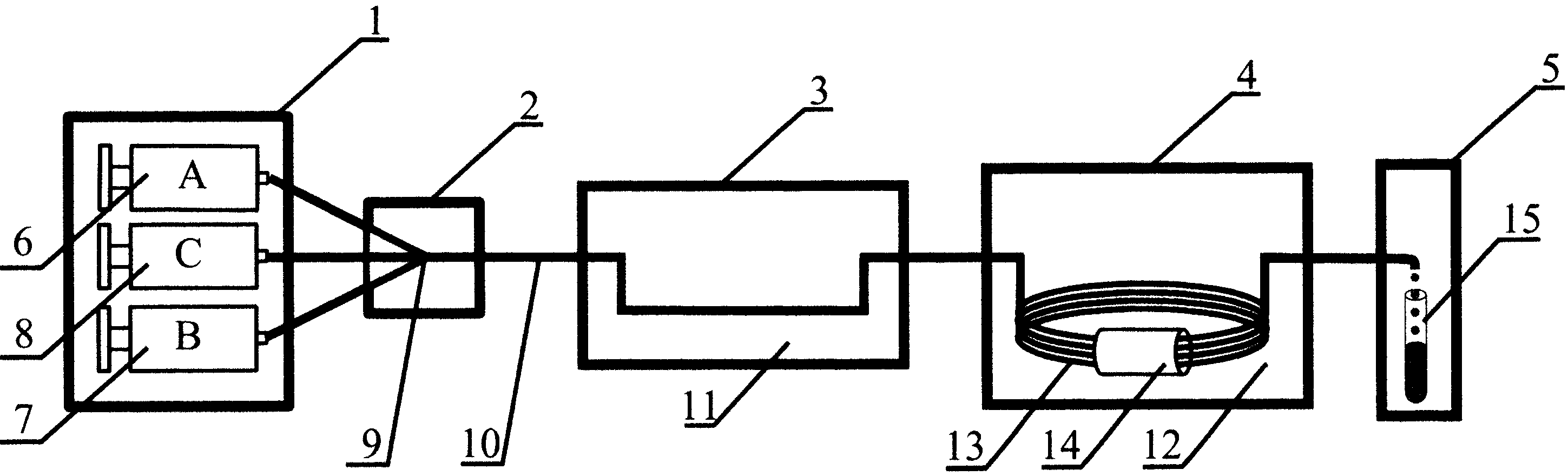
На Фиг. 1 изображена принципиальная схема реактора для получения наноструктур.In FIG. 1 shows a schematic diagram of a reactor for producing nanostructures.
Реактор для получения наноструктур содержит блок дозирования 1, блок смешивания и сегментирования 2, первый блок термостатирования 3, второй блок термостатирования 4, блок отбора 5. Перечисленные блоки соединены каналом движения материалов последовательно в указанном порядке. Блок дозирования 1 содержит насос 6 с раствором прекурсора A, насос 7 с раствором прекурсора B и насос 8 с жидкостью-носителем C, выходы которых через трубки связаны с блоком смешивания и сегментирования 2, выполненного в виде тройника-смесителя 9. Выход блок смешивания и сегментирования 2 связан с политетрафторэтиленовым (ПТФЭ) капилляром 10. Сегментированный поток смешанных прекурсоров поступает последовательно в первый блок термостатирования 3 и второй блок термостатирования 4, которые организованы в виде масляных бань 11 и 12. Часть капилляра 10 размещена в масляной бане 11. Далее в масленой бане 12 второго блока термостатирования 4 капилляр 10 сформирован в виде спирали 13, для увеличения продолжительности пребывания зародышей во втором блоке термостатирования 4. Каждый виток спирали проходит через отверстие цилиндрического постоянного магнита 14 с аксиальной намагниченностью. В блоке отбора 5 под давлением созданным насосами 6, 7, 8, синтезированные наноструктуры поступают из капилляра 10 в емкость для сбора 15.The reactor for producing nanostructures contains a metering unit 1, a mixing and segmenting unit 2, a first thermostatic control unit 3, a second
Устройство работает следующим образом.The device operates as follows.
В блоке дозирования 1 два прекурсора A, B и одна жидкость-носитель C дозируются при помощи насосов 6, 7, 8 и перемещаются по трубкам в блок смешивания и сегментирования 2, где прекурсоры смешиваются, а жидкость-носитель сегментирует смешанные прекурсоры, так как она является несмешивающейся с прекурсорами. Поток сегментированных прекурсоров, выходя из блока смешивания и сегментирования 2, попадает в ПТФЭ капилляр 10 и движется под давлением создаваемым насосами в первый блок термостатирования 3, в котором происходит нагрев сегментированного потока до температуры нуклеации с помощью масляной бани 11, что приводит к образованию зародышей из сегментированного потока прекурсоров. Далее поток сформированных зародышей по капилляру 10, перемещается во второй блок термостатирования 4, где зародыши движутся по спирали 13, где попадают под воздействие температуры роста (масляная баня 12), и магнитного поля, сформированного постоянным магнитом 14. При приложении магнитного поля вдоль осей легкого намагничивания зародышей наноструктур наблюдается ориентированный рост вытянутых, так называемых одномерных наноструктур - наностержней. В блоке отбора 5, проводится отбор полученного наноматериала в емкости для хранения 15.In dosing unit 1, two precursors A, B and one carrier fluid C are dosed using
В качестве примера реализации можно привести следующую компоновку устройства.As an example of implementation, the following device layout can be given.
В блоке дозирования 1 в качестве насосов 6, 7, 8 могут использоваться шприцевые насосы AITECS 2016, в качестве трубок соединяющих шприцевые насосы и блок смешивания и сегментирования 2 могут использоваться силиконовые капилляры с внутренним диаметром 1 мм и толщиной стенки 0,5 мм.In dosing unit 1, AITECS 2016 syringe pumps can be used as
В блоке смешивания и сегментирования 2 тройник-смеситель 9 может быть организован, например следующим образом - две силиконовые трубки одними концами связаны с насосами 6 и 7, а к другим концам присоединены иглы от инсулиновых шприцов, которые пронизывают силиконовую трубку соединенную с насосом 8 с противоположных сторон и формируют угол 90° в центре между собой, образуя герметичное уплотнение вокруг них. Другой конец силиконовой трубки связанной с насосом 8 является выходом блока смешивания и сегментирования 2.In the mixing and segmenting unit 2, the tee-
ПТФЭ капилляр имеет внутренний диаметр 0,8 мм, внешний диаметр 1,6 мм.The PTFE capillary has an inner diameter of 0.8 mm and an outer diameter of 1.6 mm.
Блоки термостатирования 3 и 4 выполнены в виде масляных бань 11, 12, в качестве которых могут использоваться масляная баня - IKA HBR 4 digital.
В качестве постоянного магнита 14 может использоваться цилиндрический неодимовый магнит с аксиальной намагниченностью, внешний диаметр которого 2 см, длина 8 см, а диаметр внутреннего отверстия 1 см, величина магнитной индукции которого может составлять: 0,2 Тл, 0,25 Тл, 0,3 Тл, 0,35 Тл. В таком случае максимальное количество витков капилляра составляет 11 витков.As a
В блоке отбора 5 в качестве емкостей для хранения 15 могут быть использованы пробирки центрифужные из пропилена с герметично завинчивающейся крышкой, типа "Фалькон", объем которых может составлять 2, 10, 15, 50 мл.In the
Для металлических опор и креплений элементов установки может применяться анодированный алюминиевый профиль 6061 компании Maker Works Technology INC.Anodized aluminum profile 6061 from Maker Works Technology INC. Can be used for metal supports and fixtures of the installation elements.
Управление режимами работы реактора, а именно скоростью работы насосов 6, 7, 8 и температурой масляных бань 11, 12, проводят, используя специальную программу для ЭВМThe control of the reactor operating modes, namely the speed of the
К условиям, влияющим на формирование тех или иных наноструктур относиться: использование различных прекурсоров, а также величина магнитного поля, которая воздействует на поток зародышей во втором блоке термостатирования. Примеры вариаций прекурсоров и величин магнитного поля для получения как наночастиц (нульмерных наноструктур) так и наностержней (одномерных наноструктур) приведены в таблице.The conditions affecting the formation of various nanostructures include: the use of various precursors, as well as the magnitude of the magnetic field, which affects the flow of nuclei in the second thermostatic control unit. Examples of variations of precursors and magnetic field values for obtaining both nanoparticles (zero-dimensional nanostructures) and nanorods (one-dimensional nanostructures) are given in the table.
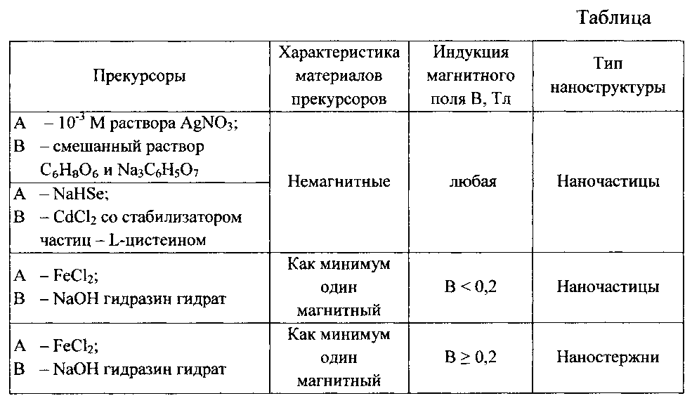
Таким образом, заявляемый реактор обеспечивает возможность получения наноструктур двух типов: наночастиц (нульмерных наноструктур) и наностержней (одномерных наноструктур) и наладить безопасное поточное массовое производство таких структур.Thus, the inventive reactor provides the ability to obtain two types of nanostructures: nanoparticles (zero-dimensional nanostructures) and nanorods (one-dimensional nanostructures) and to establish safe mass flow production of such structures.
Claims (1)
Priority Applications (1)
| Application Number | Priority Date | Filing Date | Title |
|---|---|---|---|
| RU2015155748/02U RU166323U1 (en) | 2015-12-24 | 2015-12-24 | REACTOR FOR SYNTHESIS OF NANOSTRUCTURES |
Applications Claiming Priority (1)
| Application Number | Priority Date | Filing Date | Title |
|---|---|---|---|
| RU2015155748/02U RU166323U1 (en) | 2015-12-24 | 2015-12-24 | REACTOR FOR SYNTHESIS OF NANOSTRUCTURES |
Publications (1)
| Publication Number | Publication Date |
|---|---|
| RU166323U1 true RU166323U1 (en) | 2016-11-20 |
Family
ID=57792749
Family Applications (1)
| Application Number | Title | Priority Date | Filing Date |
|---|---|---|---|
| RU2015155748/02U RU166323U1 (en) | 2015-12-24 | 2015-12-24 | REACTOR FOR SYNTHESIS OF NANOSTRUCTURES |
Country Status (1)
| Country | Link |
|---|---|
| RU (1) | RU166323U1 (en) |
-
2015
- 2015-12-24 RU RU2015155748/02U patent/RU166323U1/en not_active IP Right Cessation
Similar Documents
| Publication | Publication Date | Title |
|---|---|---|
| CN102974255B (en) | Passive spiral micro-structural mixing unit and application thereof | |
| Wang et al. | Synthesis of ZnO nanoparticles from microemulsions in a flow type microreactor | |
| Li et al. | Simple and reusable off-the-shelf microfluidic devices for the versatile generation of droplets | |
| CN106109440B (en) | A kind of preparation method of microfluidic chip and alginate magnetic microsphere | |
| CN103386336A (en) | Microfluidic chip for producing droplets with concentration gradients | |
| Yu et al. | Experimental study of double emulsion formation behaviors in a one-step axisymmetric flow-focusing device | |
| CN101565175A (en) | Device of fast synthetizing CdSe quantum dots and method thereof | |
| CN104549586B (en) | A kind of SERS self-reference micro-fluidic chip based on magnetic graphene, its preparation method and application | |
| Yang et al. | Bioinspired jellyfish microparticles from microfluidics | |
| Li et al. | Hydrothermal micro continuous-flow synthesis of spherical, cylinder-, star-and flower-like ZnO microparticles | |
| CN108927231A (en) | Multichannel drop formation device and method based on macropore perfusion microballoon | |
| CN107602874A (en) | A kind of method based on microflow control technique synthesis metal-organic framework materials | |
| Akram et al. | Hybrid effects of thermal and concentration convection on peristaltic flow of fourth grade nanofluids in an inclined tapered channel: applications of double-diffusivity | |
| Hussain et al. | Study of double diffusivity and heat conducting phenomena under the Casson nanofluid flowing through a vertical peristaltic tube | |
| Chong et al. | Design and operation of magnetophoretic systems at microscale: device and particle approaches | |
| Salman et al. | Approximate treatment for the MHD peristaltic transport of jeffrey fluid in inclined tapered asymmetric channel with effects of heat transfer and porous medium | |
| Feng et al. | Model prediction and experimental validation of transverse permeability of large-tow carbon fiber composites | |
| Nadeem et al. | Analysis of nanoparticles on peristaltic flow of Prandtl fluid model in an endoscopy | |
| Ahmed et al. | HEAT AND MASS TRANSFER EFFECTS ON THE PERISTALTIC FLOW OF SISKO FLUID IN A CURVED CHANNEL. | |
| Akhtar et al. | Analysis of magnetized bioconvective Ellis nanofluid flow: impact of viscous dissipation and activation energy | |
| Tak et al. | Comparison of tri-nanomaterial Darcy-Forchheimer flow using LNSA | |
| CN204380706U (en) | A kind of SERS self-reference micro-fluidic chip based on magnetic graphene | |
| Israel-Cookey et al. | Magnetohydrodynamic forced convection and heat transfer of a Casson fluid flow in an anisotropic porous channel with isoflux boundaries | |
| Mbwahnche et al. | Segmented flow reactor for synthesis of quantum dot nanocrystals and plasmonic nanoparticles | |
| Zhang et al. | Israr Ur Rehman, M |
Legal Events
| Date | Code | Title | Description |
|---|---|---|---|
| MM9K | Utility model has become invalid (non-payment of fees) |
Effective date: 20171225 |