RU166315U1 - WATER OIL SEPARATOR - Google Patents
WATER OIL SEPARATOR Download PDFInfo
- Publication number
- RU166315U1 RU166315U1 RU2015148625/05U RU2015148625U RU166315U1 RU 166315 U1 RU166315 U1 RU 166315U1 RU 2015148625/05 U RU2015148625/05 U RU 2015148625/05U RU 2015148625 U RU2015148625 U RU 2015148625U RU 166315 U1 RU166315 U1 RU 166315U1
- Authority
- RU
- Russia
- Prior art keywords
- gas
- filter element
- moisture
- gas pipeline
- oil separator
- Prior art date
Links
- XLYOFNOQVPJJNP-UHFFFAOYSA-N water Substances O XLYOFNOQVPJJNP-UHFFFAOYSA-N 0.000 title claims abstract description 5
- 239000011490 mineral wool Substances 0.000 claims description 3
- 239000000945 filler Substances 0.000 claims description 2
- 239000008187 granular material Substances 0.000 claims description 2
- 239000007789 gas Substances 0.000 abstract description 56
- 230000018044 dehydration Effects 0.000 abstract description 4
- 238000006297 dehydration reaction Methods 0.000 abstract description 4
- 238000001035 drying Methods 0.000 abstract description 4
- 239000003921 oil Substances 0.000 abstract description 2
- 239000000126 substance Substances 0.000 abstract description 2
- 238000000746 purification Methods 0.000 description 5
- 239000011148 porous material Substances 0.000 description 4
- 229910000323 aluminium silicate Inorganic materials 0.000 description 2
- 238000004140 cleaning Methods 0.000 description 2
- 239000002274 desiccant Substances 0.000 description 2
- HNPSIPDUKPIQMN-UHFFFAOYSA-N dioxosilane;oxo(oxoalumanyloxy)alumane Chemical compound O=[Si]=O.O=[Al]O[Al]=O HNPSIPDUKPIQMN-UHFFFAOYSA-N 0.000 description 2
- 238000005192 partition Methods 0.000 description 2
- 238000009826 distribution Methods 0.000 description 1
- 239000002657 fibrous material Substances 0.000 description 1
- -1 for example Substances 0.000 description 1
- 238000009434 installation Methods 0.000 description 1
- 239000000463 material Substances 0.000 description 1
- 239000005373 porous glass Substances 0.000 description 1
- 239000000843 powder Substances 0.000 description 1
- 238000005476 soldering Methods 0.000 description 1
- 238000009827 uniform distribution Methods 0.000 description 1
Images
Classifications
-
- B—PERFORMING OPERATIONS; TRANSPORTING
- B01—PHYSICAL OR CHEMICAL PROCESSES OR APPARATUS IN GENERAL
- B01D—SEPARATION
- B01D45/00—Separating dispersed particles from gases or vapours by gravity, inertia, or centrifugal forces
- B01D45/04—Separating dispersed particles from gases or vapours by gravity, inertia, or centrifugal forces by utilising inertia
- B01D45/06—Separating dispersed particles from gases or vapours by gravity, inertia, or centrifugal forces by utilising inertia by reversal of direction of flow
-
- B—PERFORMING OPERATIONS; TRANSPORTING
- B01—PHYSICAL OR CHEMICAL PROCESSES OR APPARATUS IN GENERAL
- B01D—SEPARATION
- B01D46/00—Filters or filtering processes specially modified for separating dispersed particles from gases or vapours
- B01D46/24—Particle separators, e.g. dust precipitators, using rigid hollow filter bodies
-
- B—PERFORMING OPERATIONS; TRANSPORTING
- B01—PHYSICAL OR CHEMICAL PROCESSES OR APPARATUS IN GENERAL
- B01D—SEPARATION
- B01D53/00—Separation of gases or vapours; Recovering vapours of volatile solvents from gases; Chemical or biological purification of waste gases, e.g. engine exhaust gases, smoke, fumes, flue gases, aerosols
- B01D53/26—Drying gases or vapours
- B01D53/266—Drying gases or vapours by filtration
Landscapes
- Chemical & Material Sciences (AREA)
- Chemical Kinetics & Catalysis (AREA)
- Engineering & Computer Science (AREA)
- Analytical Chemistry (AREA)
- General Chemical & Material Sciences (AREA)
- Oil, Petroleum & Natural Gas (AREA)
- Filtering Of Dispersed Particles In Gases (AREA)
- Separating Particles In Gases By Inertia (AREA)
Abstract
ВЛАГОМАСЛООТДЕЛИТЕЛЬWATER OIL SEPARATOR
Заявляемая полезная модель относится к области газовой, нефтяной, химической и других отраслей промышленности и может быть использована для промышленной осушки газов. The inventive utility model relates to the field of gas, oil, chemical and other industries and can be used for industrial drying of gases.
Влагомаслоотделитель содержит цилиндрический корпус, снабженный верхним основанием с отверстием для выхода газа, и нижним основанием с отверстиями для слива конденсата и входа газа. Внутри корпуса влагомаслоотделителя расположены газопровод, каплеотбойник, фильтроэлемент тонкой очистки и фильтроэлемент грубой очистки. В отличие от прототипа, газопровод расположен вдоль оси цилиндрического корпуса, нижний конец газопровода сообщен с отверстием для входа газа, а верхний конец газопровода выполнен перфорированным, на газопроводе последовательно снизу вверх размещены каплеотбойник, фильтроэлемент тонкой очистки и фильтроэлемент грубой очистки таким образом, что перфорированная часть газопровода находится внутри фильтроэлемента грубой очистки и обеспечивается возможность движения очищенного газа к отверстию для выхода газа. The moisture-oil separator comprises a cylindrical body provided with an upper base with a gas outlet and a lower base with holes for condensate drain and gas inlet. A gas pipeline, a droplet collector, a fine filter element and a rough filter element are located inside the moisture separator case. Unlike the prototype, the gas pipeline is located along the axis of the cylindrical body, the lower end of the gas pipeline is in communication with the gas inlet hole, and the upper end of the gas pipeline is perforated, a drop collector, a fine filter element and a coarse filter element are arranged sequentially from bottom to top in such a way that the perforated part the gas pipeline is located inside the coarse filter element and the purified gas can move to the gas outlet.
Технический результат - повышение качества осушки газа.The technical result is an increase in the quality of gas dehydration.
1 н. п. ф-лы, 7 з. п. ф-лы, 1 фиг. 1 n P. f-ly, 7 s. P. f-ly, 1 Fig.
Description
Заявляемая полезная модель относится к области газовой, нефтяной, химической и других отраслей промышленности и может быть использована для промышленной осушки газов.The inventive utility model relates to the field of gas, oil, chemical and other industries and can be used for industrial drying of gases.
Известен влагомаслоотделитель, содержащий установленный внутри цилиндрического корпуса фильтр первой ступени очистки, состоящий из завихрителя, каплеотбойника в виде полого усеченного конуса и фильтроэлемента первой степени очистки и фильтроэлемента второй степени очистки. Фильтроэлемент первой степени очистки выполнен в виде пористого стакана с охватывающей его снаружи непроницаемой перегородкой, а фильтроэлемент второй ступени очистки выполнен в виде полого пористого цилиндра, установленного коаксиально фильтроэлементу первой ступени очистки и охватывающего его снаружи. При этом корпус снабжен крышкой, входным и выходным патрубками, в нижней его части размещены сборники влаги и масла и устройство для спуска конденсата. [Патент на полезную модель RU 24398, дата публикации 10.08.2002, МПК B01D 45/00]Known moisture separator containing installed inside the cylindrical body of the filter of the first cleaning stage, consisting of a swirler, a droplet collector in the form of a hollow truncated cone and a filter element of the first degree of purification and a filter element of the second degree of purification. The filter element of the first degree of purification is made in the form of a porous glass with an impenetrable partition enveloping it from the outside, and the filter element of the second stage of purification is made in the form of a hollow porous cylinder mounted coaxially to the filter element of the first stage of purification and enveloping it outside. In this case, the housing is equipped with a cover, inlet and outlet pipes, in its lower part there are moisture and oil collectors and a device for draining the condensate. [Patent for utility model RU 24398, publication date 08/10/2002, IPC B01D 45/00]
Известен влагомаслоотделитель, содержащий вертикально расположенный цилиндрический корпус, с установленными один над другим фильтрующими патронами грубой и тонкой очистки из пористых материалов с различным размером пор. Фильтрующий патрон грубой очистки выполнен с размером пор (1,6-2,0) мм, а фильтрующий патрон тонкой очистки с размером пор (0,1-0,4) мм, причем соотношение площади поверхности патрона грубой очистки к площади поверхности тонкой очистки составляет 1,0:5,1-12,0, а патрон тонкой очистки имеет слой спеченного сферического порошка сформированного на его поверхности. [Патент на полезную модель RU 52734, дата публикации 27.04.2006, МПК B01D 46/00, B01D 39/00].Known moisture separator containing a vertically arranged cylindrical body, installed one above the other filter cartridges of coarse and fine cleaning from porous materials with different pore sizes. The coarse filter cartridge is made with a pore size (1.6-2.0) mm, and the fine filter cartridge with a pore size (0.1-0.4) mm, and the ratio of the surface area of the coarse cartridge to the fine surface area is 1.0: 5.1-12.0, and the fine cartridge has a layer of sintered spherical powder formed on its surface. [Patent for utility model RU 52734, publication date 04/27/2006, IPC B01D 46/00, B01D 39/00].
В качестве наиболее близкого технического решения был выбран влагомаслоотделитель, содержащий вертикальный цилиндрический корпус, в котором соосно один над другим установлены фильтрующие патроны грубой и тонкой очистки, входной и выходной патрубки. Дополнительно влагомаслоотделитель снабжен камерой-циклоном, которая образована в нижней части корпуса отделением части его объема монтажной перегородкой, в которой установлен патрубок для подачи газа из камеры-циклона в верхнюю часть корпуса, содержащую фильтрующие патроны. [Патент на полезную модель RU 5534, дата публикации 16.12.1997, МПК B01D 46/26].As the closest technical solution, a moisture separator was selected containing a vertical cylindrical body in which coarse and fine filter cartridges, inlet and outlet nozzles, are installed coaxially one above the other. In addition, the oil and water separator is equipped with a cyclone chamber, which is formed in the lower part of the housing by separating a part of its volume with a mounting partition, in which a pipe is installed for supplying gas from the cyclone chamber to the upper part of the housing containing filter cartridges. [Patent for utility model RU 5534, publication date 12/16/1997, IPC B01D 46/26].
Общим недостатком известных устройств является малая площадь соприкосновения газа с фильтром и неравномерность распределения его по поверхности фильтра, что существенно снижает качество осушки газа.A common disadvantage of the known devices is the small contact area of the gas with the filter and the uneven distribution of it on the surface of the filter, which significantly reduces the quality of gas drying.
Технической задачей заявляемой полезной модели является повышение качества осушки газа.The technical task of the claimed utility model is to improve the quality of gas dehydration.
Технический результат - повышение качества осушки газа.The technical result is an increase in the quality of gas dehydration.
Сущность заявляемого устройства заключается в следующем.The essence of the claimed device is as follows.
Влагомаслоотделитель содержит цилиндрический корпус, снабженный верхним основанием с отверстием для выхода газа, и нижним основанием с отверстиями для слива конденсата и входа газа. Внутри корпуса влагомаслоотделителя расположены газопровод, каплеотбойник, фильтроэлемент тонкой очистки и фильтроэлемент грубой очистки. В отличие от прототипа, газопровод расположен вдоль оси цилиндрического корпуса, нижний конец газопровода сообщен с отверстием для входа газа, а верхний конец газопровода выполнен перфорированным, на газопроводе последовательно снизу вверх размещены каплеотбойник, фильтроэлемент тонкой очистки и фильтроэлемент грубой очистки таким образом, что перфорированная часть газопровода находится внутри фильтроэлемента грубой очистки и обеспечивается возможность движения очищенного газа к отверстию для выхода газа.The moisture-oil separator comprises a cylindrical body provided with an upper base with a gas outlet and a lower base with holes for condensate drain and gas inlet. A gas pipeline, a droplet collector, a fine filter element and a rough filter element are located inside the moisture separator case. Unlike the prototype, the gas pipeline is located along the axis of the cylindrical body, the lower end of the gas pipeline is in communication with the gas inlet hole, and the upper end of the gas pipeline is perforated, a drop collector, a fine filter element and a coarse filter element are arranged sequentially from bottom to top in such a way that the perforated part the gas pipeline is located inside the coarse filter element and the purified gas can move to the gas outlet.
В качестве фильтроэлемента грубой очистки может быть использован гранулированный наполнитель с развитой поверхностью контакта и размером гранул не более 5 мм, например, алюмосиликатный осушитель или кольца рашига, а в качестве фильтроэлемента тонкой очистки может быть использован волокнистый материал, например, минеральная вата. Отношение объема фильтроэлемента тонкой очистки к объему фильтроэлемента грубой очистки может составлять от 1:2,3 до 1:1,5. Фильтроэлементы тонкой и грубой очистки могут быть расположены в отдельном корпусе и представлять собой двухступенчатый фильтр.As a coarse filter element, a granular filler with a developed contact surface and a granule size of not more than 5 mm, for example, an aluminosilicate desiccant or rashig rings, can be used, and a fibrous material, for example, mineral wool, can be used as a fine filter element. The ratio of the volume of the fine filter element to the volume of the rough filter element can be from 1: 2.3 to 1: 1.5. Fine and coarse filter elements can be located in a separate housing and represent a two-stage filter.
Длина перфорированной части газопровода составляет не менее, чем 1/7 длины газопровода и должна быть расположена в верхней части фильтроэлемента грубой очистки.The length of the perforated part of the pipeline is not less than 1/7 of the length of the pipeline and should be located in the upper part of the rough filter element.
Каплеотбойник может быть выполнен в виде усеченного конуса, размещенного на газопроводе без зазоров, при этом диаметр нижнего основания должен быть не меньше диаметра фильтра. Каплеотбойник устанавливается таким образом, что между нижним основанием и каплеотбойником образуется пространство, представляющее собой емкость для сбора конденсата, в которую он предварительно стекает. При этом емкость для сбора конденсата может быть снабжена датчиком уровня заполнения, что позволяет контролировать степень заполнения и снижать образующееся внутри емкости давление при ее переполнении путем слива конденсата.The droplet eliminator can be made in the form of a truncated cone placed on the gas pipeline without gaps, while the diameter of the lower base should be no less than the diameter of the filter. The droplet eliminator is installed in such a way that between the lower base and the droplet eliminator a space is formed, which is a container for collecting condensate, into which it pre-flows. In this case, the condensate collecting tank can be equipped with a fill level sensor, which allows you to control the degree of filling and reduce the pressure generated inside the tank when it is full by draining the condensate.
Возможность движения очищенного газа к отверстию для выхода газа может быть обеспечена путем размещения фильтра и каплеотбойника относительно стенок корпуса влагомаслоотделителя с зазором.The possibility of movement of the purified gas to the gas outlet can be provided by placing a filter and a droplet separator relative to the walls of the housing of the oil-separator with a gap.
Верхнее и нижнее основание могут быть присоединены к корпусу путем разъемного соединения, например, с помощью шпильки с гайкой и выполнять функцию съемных крышек с целью замены фильтроэлементов.The upper and lower base can be attached to the housing by detachable connection, for example, using a stud with a nut and perform the function of removable covers in order to replace the filter elements.
Верхняя и нижняя часть корпуса с внешней стороны могут быть снабжены верхним и нижним торцевыми фланцами соответственно, предназначенными для крепления влагомаслоотделителя, например, к панели в составе установки для осушки газа. Фланцы могут быть жестко присоединены к корпусу, например, посредством спайки, или разъемно с помощью закладного кольца, размещенного в пазе фланца между фланцем и корпусом и обеспечивающего соединение корпуса и фланца без зазора. При этом закладное кольцо препятствует срыванию фланцев и крышек влагомаслоотделителя.The upper and lower parts of the housing from the outside can be equipped with upper and lower end flanges, respectively, intended for fastening the moisture separator, for example, to the panel as part of the installation for drying gas. The flanges can be rigidly attached to the body, for example, by soldering, or detachably with the help of a snap ring placed in the groove of the flange between the flange and the body and providing connection of the body and the flange without a gap. In this case, the embedded ring prevents tearing of the flanges and covers of the oil separator.
Корпус влагомаслоотделителя может быть снабжен штуцерами, сообщенными соответственно с отверстиями для входа, выхода и слива конденсата, а также штуцером для размещения датчика уровня (заполнения).The case of the oil and water separator can be equipped with fittings, respectively connected with openings for inlet, outlet and drain of condensate, as well as a fitting for placing the level sensor (filling).
Заявляемый влагомаслоотделитель характеризуется следующими отличительными существенными признаками:The inventive moisture separator is characterized by the following distinctive essential features:
- Размещение каплеотбойника и фильтроэлементов грубой и тонкой очистки на газопроводе обеспечивает направление движения газа в фильтре сверху вниз по всей его поверхности, за счет чего повышается качество осушки газа.- Placement of the drop collector and coarse and fine filter elements on the gas pipeline ensures the direction of gas movement in the filter from top to bottom over its entire surface, thereby improving the quality of gas dehydration.
- Выполнение верхнего конца газопровода с перфорацией обеспечивает равномерное распределение газа при поступлении в фильтр и последующее равномерное прохождение газа через весь объем фильтра.- The implementation of the upper end of the gas pipeline with perforation provides a uniform distribution of gas upon entering the filter and subsequent uniform passage of gas through the entire filter volume.
- Канал движения очищенного газа к отверстию для выхода обеспечивает беспрепятственное поступление очищенного газа в отверстие для выхода газа в верхней части корпуса. Размер канала позволяет устанавливать (контролировать) необходимую скорость движения газа по направлению к отверстию для выхода газа.- The channel of movement of the purified gas to the outlet for the outlet ensures the unhindered flow of purified gas into the gas outlet in the upper part of the housing. The size of the channel allows you to set (control) the necessary gas velocity in the direction of the gas outlet.
- Конусообразная форма каплеотбойника позволяет ограничить область движения потока очищенного газа на выходе из фильтра и исключить его повторное смешение с конденсатом.- The conical shape of the droplet eliminator allows you to limit the flow area of the purified gas stream at the outlet of the filter and to exclude its repeated mixing with condensate.
Совокупность вышеперечисленных существенных признаков позволяет равномерно распределить газ на входе в фильтроэлемент грубой очистки, направить газ через фильтроэлементы сверху вниз, охватывая всю поверхность фильтроэлементов, и предотвратить повторное смешение потока очищенного газа от потока конденсата на выходе из фильтроэлемента тонкой очистки.The combination of the above essential features makes it possible to evenly distribute the gas at the inlet to the coarse filter element, direct gas through the filter elements from top to bottom, covering the entire surface of the filter elements, and prevent re-mixing of the stream of purified gas from the condensate stream at the outlet of the fine filter element.
Вышеуказанное позволяет сделать вывод о соответствии заявляемой полезной модели критериям патентоспособности "новизна".The above allows us to conclude that the claimed utility model meets the criteria of patentability "novelty."
Заявляемая полезная модель может быть выполнена из известных материалов с помощью известных средств, что позволяет судить о соответствии заявляемой полезной модели критерию патентоспособности «промышленная применимость».The inventive utility model can be made of known materials using known means, which allows to judge the compliance of the claimed utility model with the patentability criterion of "industrial applicability".
Заявляемое устройство поясняется следующими чертежами.The inventive device is illustrated by the following drawings.
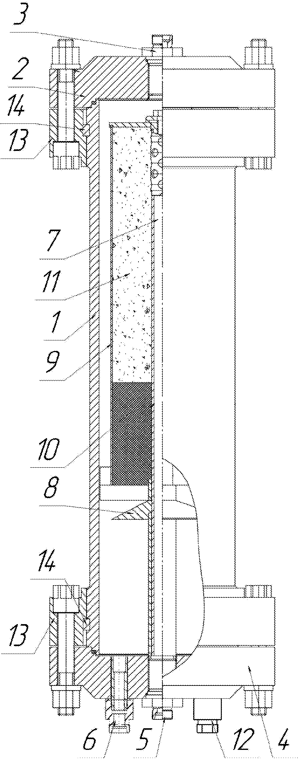
Фиг. 1 - фронтальный вид влагомаслоотделителя с местными разрезами.FIG. 1 is a front view of a moisture separator with local cuts.
Влагомаслоотделитель содержит цилиндрический корпус 1, снабженный верхней крышкой 2 с отверстием для выхода газа, сообщенным со штуцером 3, и нижней крышкой 4 с отверстием для входа газа и отверстием для слива конденсата, сообщенными соответственно со штуцерами 5 и 6. Внутри корпуса влагомаслоотделителя вдоль его оси расположен газопровод 7, при этом на нем размещены последовательно снизу вверх каплеотбойник 8 и двухступенчатый фильтр 9. Фильтр 9 и каплеотбойник 8 размещены относительно стенок корпуса 1 с зазором. Фильтр 9 заполнен последовательно минеральной ватой в качестве фильтроэлемента 10 тонкой очистки и алюмосиликатным осушителем в качестве фильтроэлемента 11 грубой очистки так, что фильтроэлемент 11 представляет собой верхний слой. При этом нижний конец газопровода 7 сообщен со штуцером 5, а верхний выполнен с перфорацией в части, на которой размещен фильтроэлемент 11. Каплеотбойник 8 выполнен в виде усеченного конуса с диаметром нижнего основания равным диаметру корпуса фильтра 9. Пространство между нижней крышкой 4 и каплеотбойником 8 образует емкость для сбора конденсата, снабженную штуцером с датчиком уровня заполнения 12. Верхняя и нижняя часть корпуса снабжены верхним и нижним торцевыми фланцами 13 для крепления влагомаслоотделителя, снабженными закладными кольцами 14, размещенными в пазе фланца между фланцем 13 и корпусом 1.The moisture-oil separator comprises a
Влагомаслоотделитель работает следующим образом.Moisture separator works as follows.
Газ под давлением 250 бар и с расходом до 1500 нм3/ч подается через штуцер 5, проходит по газопроводу 7 снизу вверх, через перфорированную трубу в верхней части газопровода поступает в корпус фильтра 9 и освобождается от мелкодисперсной влаги и масла, которые укрупняются, проходя со скоростью до 0,15 м/с сверху вниз сначала через фильтроэлемент 11, а затем через фильтроэлемент 10, и постепенно стекают под собственным весом на каплеотбойник 8 и далее на дно емкости для сбора конденсата. При этом газ, освобожденный от капельной влаги и масла, за счет уменьшения собственного веса разворачивается на 180 градусов, поднимается по зазору между стенками корпуса фильтра 9 и влагомаслоотделителя 1 наверх и выходит далее через штуцер 3. При наполнении емкости для сбора конденсата срабатывает датчик, открывается штуцер слива конденсата 6, влага и масло стекают в промежуточную емкость (не показано на чертежах).Gas at a pressure of 250 bar and with a flow rate of up to 1500 nm 3 / h is supplied through the
Claims (8)
Priority Applications (1)
| Application Number | Priority Date | Filing Date | Title |
|---|---|---|---|
| RU2015148625/05U RU166315U1 (en) | 2015-11-12 | 2015-11-12 | WATER OIL SEPARATOR |
Applications Claiming Priority (1)
| Application Number | Priority Date | Filing Date | Title |
|---|---|---|---|
| RU2015148625/05U RU166315U1 (en) | 2015-11-12 | 2015-11-12 | WATER OIL SEPARATOR |
Publications (1)
| Publication Number | Publication Date |
|---|---|
| RU166315U1 true RU166315U1 (en) | 2016-11-20 |
Family
ID=57792715
Family Applications (1)
| Application Number | Title | Priority Date | Filing Date |
|---|---|---|---|
| RU2015148625/05U RU166315U1 (en) | 2015-11-12 | 2015-11-12 | WATER OIL SEPARATOR |
Country Status (1)
| Country | Link |
|---|---|
| RU (1) | RU166315U1 (en) |
-
2015
- 2015-11-12 RU RU2015148625/05U patent/RU166315U1/en active
Similar Documents
| Publication | Publication Date | Title |
|---|---|---|
| JP5379792B2 (en) | Filter assembly and method | |
| CN101421017B (en) | Fiber bed assembly and fiber bed for the fiber bed assembly | |
| CN109011912B (en) | Coalescing filter | |
| RU2617775C1 (en) | Filtering module of liquid purification device | |
| KR20100107153A (en) | The oil separator | |
| US20050178718A1 (en) | Coalescing and separation arrangements systems and methods for liquid mixtures | |
| EA027980B1 (en) | Moisture and oil separator | |
| RU70813U1 (en) | FILTER SEPARATOR | |
| RU166315U1 (en) | WATER OIL SEPARATOR | |
| US20080257147A1 (en) | Gas Distributor | |
| RU2394623C1 (en) | Gas distributor | |
| RU2635126C1 (en) | Device for separation of vapour-liquid mixtures | |
| KR101961129B1 (en) | Rainwater filtering device using distribution appratus and seperation plate of filter element | |
| RU2325940C1 (en) | Screen vertical filter with centrifugal spraying of liquid | |
| RU2455048C1 (en) | Coalescing cartridge | |
| RU88986U1 (en) | CENTRIFUGAL DRINKER | |
| CA2270152A1 (en) | Apparatus and method for removing entrained liquid from gas or air | |
| RU110285U1 (en) | HIDDEN CARTRIDGE FILTER FOR WATER | |
| JPH05192509A (en) | Device for separating oil from oil/water mixture | |
| EP3697203B1 (en) | Filter system, installation such as an animal accommodation provided therewith, and method therefor | |
| RU94224U1 (en) | ADSORBER | |
| RU2323034C1 (en) | Device for wet-type gas collection | |
| RU130232U1 (en) | OIL AND GAS SEPARATOR | |
| RU2012108058A (en) | FILTER MODULE AND LIQUID CLEANING DEVICE | |
| RU133749U1 (en) | INSTALLATION FOR CLEANING WATER FROM OIL PRODUCTS AND MIXTURES |
Legal Events
| Date | Code | Title | Description |
|---|---|---|---|
| PD1K | Correction of name of utility model owner | ||
| QB1K | Licence on use of utility model |
Free format text: LICENCE Effective date: 20171009 |