RU166300U1 - DEVICE FOR DETERMINING THE THICKNESS OF ASPHALT CONCRETE (CONCRETE) ON THE BASIS OF GEORADAR EQUIPMENT - Google Patents
DEVICE FOR DETERMINING THE THICKNESS OF ASPHALT CONCRETE (CONCRETE) ON THE BASIS OF GEORADAR EQUIPMENT Download PDFInfo
- Publication number
- RU166300U1 RU166300U1 RU2016107853/28U RU2016107853U RU166300U1 RU 166300 U1 RU166300 U1 RU 166300U1 RU 2016107853/28 U RU2016107853/28 U RU 2016107853/28U RU 2016107853 U RU2016107853 U RU 2016107853U RU 166300 U1 RU166300 U1 RU 166300U1
- Authority
- RU
- Russia
- Prior art keywords
- thickness
- concrete
- georadar
- asphalt concrete
- transmitter
- Prior art date
Links
- 239000011384 asphalt concrete Substances 0.000 title claims abstract description 28
- 239000004567 concrete Substances 0.000 title description 15
- 238000005259 measurement Methods 0.000 claims abstract description 22
- 238000000034 method Methods 0.000 claims abstract description 21
- 230000005284 excitation Effects 0.000 claims abstract description 5
- 238000012545 processing Methods 0.000 claims abstract description 4
- 238000006073 displacement reaction Methods 0.000 claims abstract description 3
- 238000013461 design Methods 0.000 description 6
- 239000011248 coating agent Substances 0.000 description 4
- 238000000576 coating method Methods 0.000 description 4
- 238000010276 construction Methods 0.000 description 4
- 238000005553 drilling Methods 0.000 description 4
- 239000002184 metal Substances 0.000 description 4
- 230000001066 destructive effect Effects 0.000 description 3
- 238000004519 manufacturing process Methods 0.000 description 3
- 239000000463 material Substances 0.000 description 3
- 238000010586 diagram Methods 0.000 description 2
- 238000004364 calculation method Methods 0.000 description 1
- 239000003990 capacitor Substances 0.000 description 1
- 238000005520 cutting process Methods 0.000 description 1
- 238000011161 development Methods 0.000 description 1
- 230000018109 developmental process Effects 0.000 description 1
- 238000004880 explosion Methods 0.000 description 1
- 238000009434 installation Methods 0.000 description 1
- 238000011835 investigation Methods 0.000 description 1
- 238000013507 mapping Methods 0.000 description 1
- 230000000149 penetrating effect Effects 0.000 description 1
- 238000005070 sampling Methods 0.000 description 1
- 230000003068 static effect Effects 0.000 description 1
- 239000004575 stone Substances 0.000 description 1
- 239000000725 suspension Substances 0.000 description 1
- 238000004642 transportation engineering Methods 0.000 description 1
- 238000012795 verification Methods 0.000 description 1
Images
Classifications
-
- G—PHYSICS
- G01—MEASURING; TESTING
- G01B—MEASURING LENGTH, THICKNESS OR SIMILAR LINEAR DIMENSIONS; MEASURING ANGLES; MEASURING AREAS; MEASURING IRREGULARITIES OF SURFACES OR CONTOURS
- G01B15/00—Measuring arrangements characterised by the use of electromagnetic waves or particle radiation, e.g. by the use of microwaves, X-rays, gamma rays or electrons
- G01B15/02—Measuring arrangements characterised by the use of electromagnetic waves or particle radiation, e.g. by the use of microwaves, X-rays, gamma rays or electrons for measuring thickness
Landscapes
- Physics & Mathematics (AREA)
- Electromagnetism (AREA)
- General Physics & Mathematics (AREA)
- Road Repair (AREA)
- Radar Systems Or Details Thereof (AREA)
Abstract
1. Устройство для определения толщины асфальтобетона, представляющее собой георадар с бесконтактным антенным блоком, отличающееся тем, что в антенном блоке будет всего один приемник и один передатчик, расстояние между которыми изменяется в процессе измерений за счет использования раздвижного кронштейна.2. Устройство по п. 1 отличающееся тем, что может быть произведено по типу моноблок, когда антенный блок, блок управления, блок обработки, датчик перемещения и блок питания располагаются в одном корпусе.3. Устройство по п. 1 отличающееся тем, что может работать по способу общего пункта возбуждения и общего пункта приема.1. A device for determining the thickness of asphalt concrete, which is a georadar with a contactless antenna unit, characterized in that there will be only one receiver and one transmitter in the antenna unit, the distance between which changes during the measurement due to the use of a sliding bracket. 2. The device according to claim 1, characterized in that it can be manufactured as a monoblock, when the antenna unit, control unit, processing unit, displacement sensor and power supply unit are located in one housing. The device according to claim 1, characterized in that it can operate according to the method of a common point of excitation and a common point of reception.
Description
Асфальтобетон (бетон) является одним из наиболее дорогих материалов в конструкциях дорожных одежд, поэтому очевидно стремление дорожников обеспечить соответствие толщины асфальтобетонных (бетонных) слоев проектным данным. Метод отбора кернов монолитных материалов позволяет выборочно контролировать толщину асфальтобетонных (бетонных) слоев после их устройства, при этом негативно влияет на долговечность дорожной конструкции, является ресурсоемким и приводит к существенным издержкам пользователей автомобильных дорог высокой интенсивности движения. Устройство для определения толщины асфальтобетона (бетона) на базе георадарного оборудования предлагается в качестве альтернативы отбору кернов при георадиолокационных измерениях.Asphalt concrete (concrete) is one of the most expensive materials in the construction of pavement, therefore, the striving of road workers to ensure that the thickness of the asphalt concrete (concrete) layers is consistent with design data is obvious. The method of coring of monolithic materials allows you to selectively control the thickness of asphalt concrete (concrete) layers after their installation, while negatively affecting the durability of the road structure, is resource-intensive and leads to significant costs for users of high-traffic roads. A device for determining the thickness of asphalt concrete (concrete) based on georadar equipment is proposed as an alternative to coring during georadar measurements.
Полезная модель описывает устройство, изготовленное на базе георадарного оборудования, применяемое в основном для измерения толщины пакета и отдельных асфальтобетонных (бетонных) слоев дорожной одежды на автомобильных дорогах и взлетно-посадочных полосах аэродромов в ходе операционного и приемочного контроля при выполнении дорожно-строительных работ. Но может применяться и для определения толщины слоев основания дорожной одежды в ходе послойного их устройства. Техническим результатом применения данного устройства является повышение точности измерения толщины асфальтобетонных (бетонных) слоев не разрушающим способом, которое обеспечивается измерениями в режиме годографа и высокой плотностью точек годографа за счет использования раздвижного кронштейна (в т.ч. с узким диапазоном хода), при этом применяется исключительно бесконтактный (рупорный антенный) блок, оснащенный всего одним приемником и одним передатчиком.The utility model describes a device made on the basis of georadar equipment, which is mainly used to measure the thickness of a package and individual asphalt concrete (concrete) layers of pavement on roads and runways of airfields during operational and acceptance control during road construction works. But it can also be used to determine the thickness of the layers of the base of the pavement during the layering of their device. The technical result of the use of this device is to increase the accuracy of measuring the thickness of asphalt concrete (concrete) layers in a non-destructive way, which is ensured by measurements in the hodograph mode and a high density of hodograph points due to the use of a sliding bracket (including with a narrow range of travel), exclusively non-contact (horn antenna) unit, equipped with only one receiver and one transmitter.
Способ измерения толщины слоев подповерхностной среды, основанный на работе георадара в режиме годографа (когда передатчик перемещается относительно приемника), является довольно известным [1], однако он применялся для решения задач инженерной геологии (определение толщины слоев естественной геологической среды) с использованием контактных (грунтовых) антенных блоков.A method of measuring the thickness of layers of a subsurface medium, based on the operation of the GPR in the travel time mode (when the transmitter moves relative to the receiver), is quite known [1], but it was used to solve problems of engineering geology (determining the thickness of layers of a natural geological environment) using contact (ground ) antenna units.
Годограф отраженной волны описывается уравнением (1) [1].The hodograph of the reflected wave is described by equation (1) [1].

где t - время прихода электромагнитной волны в точку на оси синфазности, снятое с радарограммы;where t is the time of arrival of the electromagnetic wave at a point on the in-phase axis, taken from the radarogram;
h - толщина слоя;h is the thickness of the layer;
х - расстояние от передающей антенны до приемной;x is the distance from the transmitting antenna to the receiving;
V - скорость распространения волн в слое.V is the velocity of propagation of waves in the layer.
Поскольку величины h и V являются неизменными для узкого диапазона обследуемой среды, имея 2 точки годографа и более можно выразить величину h. Предлагаемое устройство позволяет получить большое количество точек годографа (в т.ч. в узком диапазоне обследуемой среды), что повышает точность измерения толщины слоев асфальтобетона (бетона). Стоит отметить, что при осуществлении измерений в режиме годографа оцениваются прямые, а не косвенные зависимости, наряду с использованием бесконтактных (рупорных) антенн это позволяет минимизировать погрешность определения толщины слоев асфальтобетона (бетона).Since the values of h and V are unchanged for a narrow range of the medium under study, having 2 hodograph points or more, the value of h can be expressed. The proposed device allows to obtain a large number of hodograph points (including in a narrow range of the medium under study), which increases the accuracy of measuring the thickness of the layers of asphalt concrete (concrete). It is worth noting that when measuring in the hodograph mode, direct rather than indirect dependencies are evaluated, along with the use of contactless (horn) antennas this allows you to minimize the error in determining the thickness of the layers of asphalt concrete (concrete).
Измерение толщины асфальтобетонных (бетонных) слоев дорожной одежды с помощью георадарного оборудования в настоящее время, преимущественно, осуществляется либо по методу георадиолокационного профилирования с заверкой путем отбора кернов, либо по методу амплитуд. В обоих случаях применяют бесконтактные (рупорные) антенные блоки георадара, в которых приемник и передатчик сигнала неподвижны относительно друг друга (измерения на постоянной базе). Такая конструкция антенного блока позволяет получать непрерывный разрез подповерхностной среды с заданным шагом зондирования, обеспечивает возможность контроля относительного изменения толщины слоя, но не позволяет определять его абсолютные значения без заверки буровыми работами.The thickness measurement of asphalt concrete (concrete) layers of pavement using georadar equipment is currently mainly carried out either by the method of georadar profiling with verification by coring, or by the method of amplitudes. In both cases, non-contact (horn) antenna units of the georadar are used, in which the receiver and transmitter of the signal are stationary relative to each other (measurements on a constant base). This design of the antenna unit allows you to get a continuous section of the subsurface medium with a given sounding step, provides the ability to control the relative changes in the layer thickness, but does not allow to determine its absolute values without certification by drilling operations.
В ходе измерений по методу георадиолокационного профилирования с определенной периодичностью по трассе осуществляется отбор кернов, который позволяет локально получать фактические значения толщины слоев и относительно этих значений определять глубину заложения подошвы слоев при помощи георадара. При этом существенно снижаются межремонтные сроки дорожных конструкций, на период бурения приходиться перекрывать полосу движения, в кратчайшие сроки к местам пройденных вырубок необходимо доставлять равнопрочный материал для их заделки, а на покрытии искусственных сооружений отбор кернов не допускается вовсе.In the course of measurements by the method of georadar-tracking profiling with a certain periodicity along the route, core sampling is carried out, which allows locally to obtain actual values of the thickness of the layers and to determine the depth of the sole of the layers relative to these values using georadar. At the same time, the overhaul periods of road structures are significantly reduced, it is necessary to cover the traffic lane during the drilling period, as soon as possible, equal-strength material must be delivered to the places of clearcuts to seal them, and coring is not allowed at all.
При использовании метода амплитуд [2] бесконтактный (рупорный) антенный блок георадара вывешивают над металлическим листом и выполняют георадиолокационные измерения. Затем осуществляют традиционные измерения методом георадиолокационного профилирования или зондирования. В ходе указанных процедур измеряют амплитуду отраженного сигнала от металлического листа и поверхности асфальтобетонного покрытия. Расчет толщины асфальтобетонных слоев при измерениях методом амплитуд производится по общеизвестной формуле (2) [2].When using the method of amplitudes [2], the non-contact (horn) antenna unit of the georadar is hung over a metal sheet and georadar measurements are performed. Then carry out traditional measurements by georadar profiling or sounding. During these procedures, the amplitude of the reflected signal from the metal sheet and the surface of the asphalt concrete coating is measured. Calculation of the thickness of asphalt concrete layers during measurements by the amplitude method is performed according to the well-known formula (2) [2].
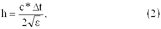
где, h - толщина слоя;where, h is the thickness of the layer;
с - скорость света в вакууме;c is the speed of light in vacuum;
Δt - двойное время пробега волны;Δt is the double travel time of the wave;
ε - диэлектрическая проницаемость.ε is the dielectric constant.
При этом диэлектрическая проницаемость определяется по формуле (3) [2].In this case, the dielectric constant is determined by the formula (3) [2].
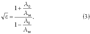
где, А0 - амплитуда отражения от поверхности асфальтобетонного покрытия;where, A 0 is the amplitude of reflection from the surface of the asphalt concrete pavement;
Ам - амплитуда отражения от поверхности металлической пластины.And m is the amplitude of reflection from the surface of the metal plate.
Недостатком таких измерений является относительная точность данных, поскольку для определения толщины слоя используются не прямые, а косвенные зависимости. Кроме того, метод амплитуд позволяет определять толщину лишь первого слоя относительно поверхности.The disadvantage of such measurements is the relative accuracy of the data, since indirect dependences are used to determine the layer thickness. In addition, the amplitude method allows you to determine the thickness of only the first layer relative to the surface.
Известен ряд других приборов и устройств измерения толщины асфальтобетонных слоев.A number of other instruments and devices for measuring the thickness of asphalt concrete layers are known.
Существует прибор оперативного контроля толщины и качества дорожных покрытий, разработанный М.И. Фильковским и Ю.А. Дашевским [3], [4]. Прибор работает по принципу бурового зондирования (определяется удельное сопротивление слоев). Осуществляется бурение с покрытия и с помощью математического алгоритма, записанного в блок обработки прибора, на основании полученных значений удельного сопротивления происходит построение графиков, по которым возможна интерпретация и картирование разреза по слоям. Несмотря на малый диаметр бура (0,8 см), прибор относится к разрушающим, при этом его применение сопровождается теми же недостатками, связанными с ограничением движения и необходимостью заделки вырубок.There is a device for operational control of the thickness and quality of pavements developed by M.I. Filkovsky and Yu.A. Dashevsky [3], [4]. The device operates on the principle of drilling sounding (determined by the resistivity of the layers). Drilling from the coating is carried out and using a mathematical algorithm recorded in the processing unit of the device, based on the obtained values of resistivity, graphs are constructed according to which interpretation and mapping of the section through layers is possible. Despite the small diameter of the drill (0.8 cm), the device is destructive, while its use is accompanied by the same disadvantages associated with the restriction of movement and the need to seal cuttings.
Известно устройство для определения толщины асфальтобетонных слоев, работающее по принципу емкостного способа [5]. В данном случае слой асфальтобетона рассматривается как конденсатор, а по его емкости можно судить о геометрических размерах, в том числе и толщине. Для получения результатов требуются базы предварительно рассчитанных зависимостей емкости от расстояния между электродом и поверхностью покрытия. В свою очередь на расчетные значения существенным образом будет влиять геометрия слоя, подстилающего асфальтобетонный слой, а он скрыт и не доступен для прямых измерений. Указанное обстоятельство является ограничением практического применения данного устройства.A device for determining the thickness of asphalt concrete layers, operating on the principle of a capacitive method [5]. In this case, the layer of asphalt concrete is considered as a capacitor, and its capacity can be used to judge the geometric dimensions, including the thickness. To obtain results, a database of previously calculated capacitance dependences on the distance between the electrode and the coating surface is required. In turn, the calculated values will be significantly affected by the geometry of the layer underlying the asphalt concrete layer, and it is hidden and not available for direct measurements. This circumstance is a limitation of the practical use of this device.
За рубежом для определения толщины асфальтобетонных слоев применяют устройства производства MIT Mess- und ![]()
![]()
В последние годы становятся очень перспективными георадары, антенные блоки которых содержат большое количество приемников и передатчиков, например 3-D Radar (Норвегия) [7]. Именно эти приборы являются наиболее близкими аналогами предлагаемого устройства. За счет большого количества приемников и передатчиков они могут эмитировать работу георадара в режиме годографа, при этом сами приемники и передатчики остаются неподвижными относительно друг друга. Плотность точек годографа определяется количеством приемников и передатчиков, а также расстоянием между ними. Неподвижная конструкция не позволяет получать такую плотность точек годографа, в т.ч. в узком диапазоне обследуемой среды, как посредством использования перемещающихся относительно друг друга приемника и передатчика, при этом наиболее существенным недостатком является высокая себестоимость подобных систем.In recent years, georadars have become very promising, the antenna units of which contain a large number of receivers and transmitters, for example 3-D Radar (Norway) [7]. These devices are the closest analogues of the proposed device. Due to the large number of receivers and transmitters, they can emit the georadar in hodograph mode, while the receivers and transmitters themselves remain stationary relative to each other. The density of hodograph points is determined by the number of receivers and transmitters, as well as the distance between them. The fixed structure does not allow to obtain such a density of hodograph points, incl. in a narrow range of the medium under investigation, as through the use of a receiver and a transmitter moving relative to each other, the most significant drawback being the high cost of such systems.
В основу полезной модели положена задача создания производительного неразрушающего устройства, обеспечивающего возможность определения толщины асфальтобетонных (бетонных) слоев дорожной одежды с минимальными погрешностями измерений, не требующего дополнительных калибровок, не имеющего ограничений по конструктивным особенностям дорожной одежды, имеющего максимально простую и надежную конструкцию, позволяющего решать указанные задачи при минимальной себестоимости его производства.The utility model is based on the task of creating a productive non-destructive device that provides the ability to determine the thickness of asphalt concrete (concrete) layers of pavement with minimal measurement errors, does not require additional calibrations, has no restrictions on the design features of pavement, which has the simplest and most reliable design that allows solving these tasks at the minimum cost of its production.
С целью решения поставленных задач устройство для определения толщины асфальтобетона, представляющее собой георадар с бесконтактным (рупорным) антенным блоком, будет отличаться тем, что в антенном блоке будет всего один приемник и один передатчик, расстояние между которыми будет изменяться в процессе измерений за счет использования раздвижного кронштейна (в т.ч. с узким диапазоном хода).In order to solve the tasks, a device for determining the thickness of asphalt concrete, which is a georadar with a contactless (horn) antenna unit, will be different in that there will be only one receiver and one transmitter in the antenna unit, the distance between which will change during the measurement due to the use of a sliding bracket (including with a narrow range of travel).
При этом устройство может устанавливаться на автомобиль (мототехнику), каток или тележку, буксируемую оператором.In this case, the device can be installed on a car (motor equipment), a roller or a trolley towed by an operator.
Кроме того устройство может быть произведено по типу моноблок (антенный блок, блок управления, блок обработки, датчик перемещения и блок питания в одном корпусе), либо состоять из отдельных компонентов. При этом приемник и передатчик рупорного (бесконтактного) антенного блока, закрепленные на раздвижном кронштейне, могут быть установлены в едином корпусе, либо иметь отдельные корпуса.In addition, the device can be manufactured as a monoblock (antenna unit, control unit, processing unit, displacement sensor and power supply in one housing), or consist of separate components. At the same time, the receiver and transmitter of the horn (non-contact) antenna unit, mounted on a sliding bracket, can be installed in a single housing, or have separate housing.
Кроме того, устройство может работать как в режиме годографа, так и по методу георадиолокационного профилирования или зондирования (когда во время измерения расстояние между приемником и передатчиком не изменяется). При этом георадиолокационные измерения в режиме годографа могут производиться по способу общего пункта возбуждения (взрыва), общего пункта приема и по методу общей глубинной точки.In addition, the device can operate both in the hodograph mode and by the method of georadar profiling or sounding (when the distance between the receiver and transmitter does not change during measurement). At the same time, georadar measurements in the hodograph mode can be performed by the method of a common point of excitation (explosion), a common point of reception, and by the method of a common deep point.
Устройство позволит повысить точность измерения толщины асфальтобетонных (бетонных) слоев за счет более высокой плотности точек годографа (в т.ч. в узком диапазоне обследуемой среды), при этом использование всего одного приемника и одного передатчика позволят обеспечить более простую конструкцию устройства и минимальную себестоимость его производства.The device will improve the accuracy of measuring the thickness of asphalt concrete (concrete) layers due to the higher density of hodograph points (including in a narrow range of the medium under study), while using only one receiver and one transmitter will allow for a simpler device design and its minimum cost production.
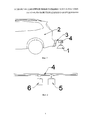
На фиг. 1 показан рупорный (бесконтактный) антенный блок 1 устройства по измерению толщины асфальтобетонных (бетонных) слоев, закрепленный на автомобиль 2 при помощи подвески 3 с раздвижным кронштейном 4.In FIG. 1 shows a horn (non-contact)
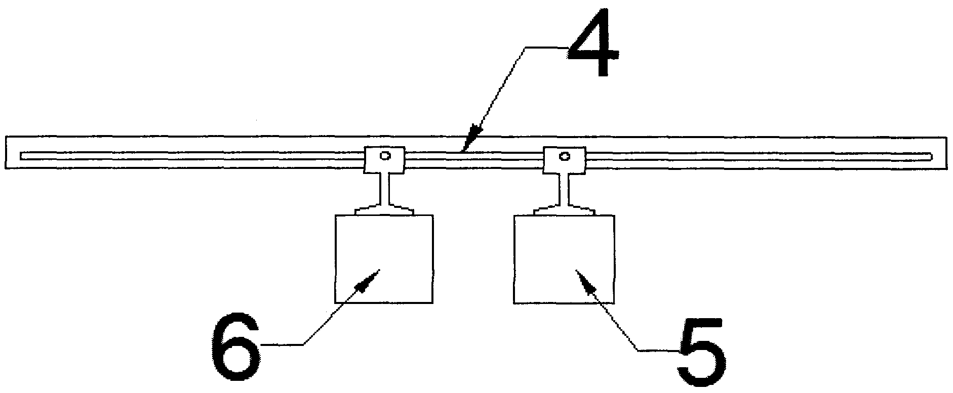
На фиг. 2 показана схема конструкции рупорного (бесконтактного) антенного блока устройства, состоящего из раздвижного кронштейна 4, закрепленных на нем приемника 5 и передатчика 6.In FIG. 2 shows a design diagram of a horn (non-contact) antenna unit of the device, consisting of a
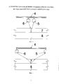
На фиг. 3 и 4 показана схема работы устройства в режиме годографа на примере метода общей глубинной точки.In FIG. Figures 3 and 4 show a diagram of the device in hodograph mode using the example of the common depth point method.
Принцип работы устройства основан на изменении расстояния между приемником и передатчиком бесконтактного (рупорного) антенного блока георадара в ходе осуществления записи георадиолокационных данных. На фиг. 3 и 4 дорожная конструкция представлена пакетом асфальтобетонных слоев 7, уложенных на щебеночное основание 8. Антенный блок устройства, состоящий из раздвижного кронштейна 4 с закрепленными на нем приемником 5 и передатчиком 6 вывешен над поверхностью покрытия с отрывом в несколько десятков сантиметров. До выполнения измерений приемник 5 и передатчик 6 находятся в исходном положении (см. фиг. 3), при этом расстояние между ними минимальное. Во время измерения приемник 5 и передатчик 6 равномерно начинают удаляться друг от друга, достигая своего крайнего положения (см. фиг. 4), при этом расстояние между ними становиться максимальным. По окончании измерения приемник 5 и передатчик 6 возвращаются в исходное положение (см. фиг. 3).The principle of operation of the device is based on changing the distance between the receiver and the transmitter of the contactless (horn) antenna unit of the georadar during recording of georadar data. In FIG. 3 and 4, the road structure is represented by a package of asphalt
Рупорный (бесконтактный) антенный блок устройства, установленный на автомобиль (каток, мототехнику, передвижную тележку) совместно с другими компонентами образует комплекс георадарного оборудования. Во время измерения в режиме годографа георадарный комплекс, преимущественно, не меняет координаты планового положения (стоит на месте), либо двигается с минимальной скоростью. Далее при движении комплекса запись георадиолокационных данных осуществляется методом традиционного профилирования на постоянной базе (расстояние между приемником и передатчиком не меняется). Периодически георадарный комплекс останавливают (замедляют) и выполняют измерения толщины слоев асфальтобетона (бетона) в режиме годографа. На основании полученных значений толщины, измеренных в режиме годографа, производится перерасчет значений толщины слоя, полученных по методу георадиолокационного профилирования.The horn (non-contact) antenna unit of the device installed on the car (skating rink, motor equipment, mobile trolley) together with other components forms a complex of georadar equipment. During the measurement in the hodograph mode, the georadar complex, mainly, does not change the coordinates of the planned position (stands still), or moves at a minimum speed. Further, when the complex moves, the GPR data are recorded using the traditional profiling method on a constant basis (the distance between the receiver and transmitter does not change). Periodically, the GPR complex is stopped (slowed down) and thickness measurements of the layers of asphalt concrete (concrete) are performed in the travel time mode. Based on the obtained thickness values measured in the hodograph mode, the layer thickness values obtained by the GPR profiling method are recalculated.
Передвигая приемник относительно передатчика, передатчик относительно приемника или равномерно перемещая приемник и передатчик относительно друг друга, с помощью раздвижного кронштейна, предоставляется возможность определить скорость электромагнитной волны в слое асфальтобетона (бетона), его диэлектрическую проницаемость и собственно толщину слоя. При этом высокая плотность точек годографа (в т.ч. в узком диапазоне обследуемой среды) позволяет повысить точность измерений толщины слоя.By moving the receiver relative to the transmitter, the transmitter relative to the receiver, or evenly moving the receiver and the transmitter relative to each other, using the sliding bracket, it is possible to determine the speed of the electromagnetic wave in the asphalt concrete layer (concrete), its dielectric constant and the actual layer thickness. At the same time, the high density of hodograph points (including in a narrow range of the medium under study) allows one to increase the accuracy of measurements of the layer thickness.
При работе по способу общего пункта возбуждения приемник двигается относительно неподвижного передатчика, и, наоборот, при работе по способу общего пункта приема передатчик двигается относительно неподвижного приемника.When working according to the method of a common point of excitation, the receiver moves relative to a stationary transmitter, and, conversely, when working according to the method of a common point of excitation, the transmitter moves relative to a stationary receiver.
Источники информации принятые во внимание.Sources of information taken into account.
1. ВЛАДОВ М.Л., СТАРОВОЙТОВ А.В. ВВЕДЕНИЕ В ГЕОРАДИОЛОКАЦИЮ // Учебное пособие - М.: Издательство МГУ, 2004. - 153 с.1. VLADOV M.L., STAROVOYTOV A.V. INTRODUCTION TO GEORADOISTRATION // Textbook - Moscow: Publishing House of Moscow State University, 2004. - 153 p.
2. Curtis Berthelot Ph.D., P. Eng., Tom Scullion P.E., Ron Gerbrandt P. Eng., Larry Safronetz APPLICATION OF GROUND PENETRATING RADAR FOR COLD IN-PLACE RECYCLED ROAD SYSTEMS // Journal of Transportation Engineering American Society for Civil Engineers / Jul/Aug 2001 Vol. 127 No 4.2. Curtis Berthelot Ph.D., P. Eng., Tom Scullion PE, Ron Gerbrandt P. Eng., Larry Safronetz APPLICATION OF GROUND PENETRATING RADAR FOR COLD IN-PLACE RECYCLED ROAD SYSTEMS // Journal of Transportation Engineering American Society for Civil Engineers / Jul / Aug 2001 Vol. 127
3. Аннотированный сборник научных разработок в сфере дорожного хозяйства (2000-2005 гг.) ФГУП «ИНФОРМАВТОДОР» Москва - 2005.3. An annotated collection of scientific developments in the field of road facilities (2000-2005) FSUE INFORMAVTODOR Moscow - 2005.
4. Наука и транспорт. Транспортное строительство. 2012. №4.4. Science and transport. Transport construction. 2012. No4.
5. Фильковский М.И., Дашевский Ю.А. Емкостный способ определения толщины асфальтобетонного покрытия - RU №2295701 С2 - 2005.5. Filkovsky M.I., Dashevsky Yu.A. Capacitive method for determining the thickness of asphalt concrete pavement - RU No. 2295701 C2 - 2005.
6. MIT Mess- und ![]()
![]()
7. Lapland University of Applied Sciences [Электронный ресурс] - http://maranord.ramk.fi/static/content_files/3d-Radar_MARA_Nord_2012.pdf - дата обращения - 22.02.2016.7. Lapland University of Applied Sciences [Electronic resource] - http://maranord.ramk.fi/static/content_files/3d-Radar_MARA_Nord_2012.pdf - date of access - 02.22.2016.
Claims (3)
Priority Applications (1)
| Application Number | Priority Date | Filing Date | Title |
|---|---|---|---|
| RU2016107853/28U RU166300U1 (en) | 2016-03-03 | 2016-03-03 | DEVICE FOR DETERMINING THE THICKNESS OF ASPHALT CONCRETE (CONCRETE) ON THE BASIS OF GEORADAR EQUIPMENT |
Applications Claiming Priority (1)
| Application Number | Priority Date | Filing Date | Title |
|---|---|---|---|
| RU2016107853/28U RU166300U1 (en) | 2016-03-03 | 2016-03-03 | DEVICE FOR DETERMINING THE THICKNESS OF ASPHALT CONCRETE (CONCRETE) ON THE BASIS OF GEORADAR EQUIPMENT |
Publications (1)
| Publication Number | Publication Date |
|---|---|
| RU166300U1 true RU166300U1 (en) | 2016-11-20 |
Family
ID=57792854
Family Applications (1)
| Application Number | Title | Priority Date | Filing Date |
|---|---|---|---|
| RU2016107853/28U RU166300U1 (en) | 2016-03-03 | 2016-03-03 | DEVICE FOR DETERMINING THE THICKNESS OF ASPHALT CONCRETE (CONCRETE) ON THE BASIS OF GEORADAR EQUIPMENT |
Country Status (1)
| Country | Link |
|---|---|
| RU (1) | RU166300U1 (en) |
Cited By (3)
| Publication number | Priority date | Publication date | Assignee | Title |
|---|---|---|---|---|
| CN108645674A (en) * | 2018-05-11 | 2018-10-12 | 西安公路研究院 | A kind of light colour pitch light transmittance rapid detection method |
| CN115479529A (en) * | 2022-09-16 | 2022-12-16 | 江苏现代工程检测有限公司 | A rapid non-destructive testing method for full-section thickness of asphalt pavement |
| CN116065462A (en) * | 2023-03-14 | 2023-05-05 | 衡水路桥工程有限公司 | Road construction quality detection device and detection method |
-
2016
- 2016-03-03 RU RU2016107853/28U patent/RU166300U1/en active IP Right Revival
Cited By (3)
| Publication number | Priority date | Publication date | Assignee | Title |
|---|---|---|---|---|
| CN108645674A (en) * | 2018-05-11 | 2018-10-12 | 西安公路研究院 | A kind of light colour pitch light transmittance rapid detection method |
| CN115479529A (en) * | 2022-09-16 | 2022-12-16 | 江苏现代工程检测有限公司 | A rapid non-destructive testing method for full-section thickness of asphalt pavement |
| CN116065462A (en) * | 2023-03-14 | 2023-05-05 | 衡水路桥工程有限公司 | Road construction quality detection device and detection method |
Similar Documents
| Publication | Publication Date | Title |
|---|---|---|
| Solla et al. | A review of GPR application on transport infrastructures: Troubleshooting and best practices | |
| US9377528B2 (en) | Roaming mobile sensor platform for collecting geo-referenced data and creating thematic maps | |
| Liu et al. | Measurement of soil water content using ground-penetrating radar: A review of current methods | |
| US8680865B2 (en) | Single well reservoir imaging apparatus and methods | |
| Chalikakis et al. | Contribution of geophysical methods to karst-system exploration: an overview | |
| Leng et al. | An innovative method for measuring pavement dielectric constant using the extended CMP method with two air-coupled GPR systems | |
| RU166300U1 (en) | DEVICE FOR DETERMINING THE THICKNESS OF ASPHALT CONCRETE (CONCRETE) ON THE BASIS OF GEORADAR EQUIPMENT | |
| KR101267016B1 (en) | Singnal apparatus for the survey of buriedstructures by used gpr unit | |
| US20180031731A1 (en) | System and method for incorporating ground penetrating radar equipment on seismic source | |
| Tomecka-Suchoń et al. | Application of GPR and seismic methods for noninvasive examination of glacial and postglacial sediments in the Psia Trawka glade: the Tatra Mts., Poland | |
| Zhen et al. | Internal structure and trend of glacier change assessed by geophysical investigations | |
| Frid et al. | Features of a large-scale survey of highways with georadar | |
| Pupatenko et al. | Lithological profiling of rocky slopes using GeoReader software based on the results of ground penetrating radar method | |
| Almalki et al. | Efficiency of seismic attributes in detecting near-surface cavities | |
| Ghozzi et al. | An innovative technique for estimating the radius of buried cylindrical targets using GPR | |
| Pupatenko et al. | GPR data interpretation in the landslides and subgrade slope surveys | |
| Anbazhagan | Subsurface investigation—integrated and modern approach | |
| CN115826063A (en) | Method for realizing high-resolution data acquisition in large-depth detection | |
| Sakhapov et al. | Innovative technology for monitoring pavements | |
| Butchibabu et al. | Delineation of Water Seepage Flow Path in the Underground Metro Rail Tunnel Using Cross-Hole GPR Tomography: A Case Study | |
| Balasubramani | Applications of Geophysical Techniques in Geotechnical Engineering | |
| Siddiqui et al. | Underground coal mines unexplored strata structure identification with subsurface profiling: a case study of inherent fault-detection method | |
| Hugenschmidt | Ground penetrating radar for the evaluation of reinforced concrete structures | |
| Zhang et al. | Forward Modeling and Detection of the Potential Slip in Artificial Slope by GPR | |
| Dera | Assessment of highway condition using combined geophysical surveys |
Legal Events
| Date | Code | Title | Description |
|---|---|---|---|
| MM9K | Utility model has become invalid (non-payment of fees) |
Effective date: 20180304 |
|
| NF9K | Utility model reinstated |
Effective date: 20200519 |