RU15934U1 - DEVICE FOR MONITORING POWER SENSORS - Google Patents
DEVICE FOR MONITORING POWER SENSORS Download PDFInfo
- Publication number
- RU15934U1 RU15934U1 RU2000110612/20U RU2000110612U RU15934U1 RU 15934 U1 RU15934 U1 RU 15934U1 RU 2000110612/20 U RU2000110612/20 U RU 2000110612/20U RU 2000110612 U RU2000110612 U RU 2000110612U RU 15934 U1 RU15934 U1 RU 15934U1
- Authority
- RU
- Russia
- Prior art keywords
- container
- load
- sensor
- bed
- disks
- Prior art date
Links
- 238000012544 monitoring process Methods 0.000 title claims abstract description 11
- 210000000078 claw Anatomy 0.000 claims abstract description 9
- 238000000034 method Methods 0.000 description 3
- 238000013461 design Methods 0.000 description 2
- 238000009434 installation Methods 0.000 description 2
- 239000000725 suspension Substances 0.000 description 2
- 230000015572 biosynthetic process Effects 0.000 description 1
- 238000010276 construction Methods 0.000 description 1
- 239000000463 material Substances 0.000 description 1
- 239000002184 metal Substances 0.000 description 1
- 238000012360 testing method Methods 0.000 description 1
- 238000012795 verification Methods 0.000 description 1
Landscapes
- Forklifts And Lifting Vehicles (AREA)
Abstract
1. Устройство для контроля силоизмерительных датчиков, содержащее станину в виде установленной на колоннах опорной плиты, на которой установлен узел для закрепления контролируемых датчиков со средствами приложения силы и регистрации, и подъемный механизм с приспособлением для поочередного нагружения датчика образцовыми грузами, выполненными в виде дисков, отличающееся тем, что приспособление для поочередного нагружения датчика выполнено в виде контейнера, состоящего из двух соединенных стяжками фланцев, внутри которого размещены образцовые грузы, нижний из которых соединен тягой, проходящей через его центр вращения, со средством приложения силы, а остальные, каждый из которых снабжен тремя симметрично размещенными по образующей выступами, взаимодействующими с лапками захватов, выполнены с центральными отверстиями, через которые проходит тяга, при этом лапки захватов каждого из дисков-грузов смещены относительно соседнего по образующей.2. Устройство по п.1, отличающееся тем, что захваты выполнены с возможностью их вертикального перемещения.3. Устройство по п.1, отличающееся тем, что станина снабжена второй опорной плитой, жестко соединенной с нижними концами колонн, и снабженной регулируемыми по высоте опорами.4. Устройство по п.1, отличающееся тем, что подъемный механизм выполнен в виде червячной пары.5. Устройство по п.1, отличающееся тем, что нижний груз изолирован электрически от контейнера, а устройство снабжено омметром, один вывод которого соединен электрически с нижним грузом, а второй - с контейнером.1. A device for monitoring load cells, comprising a bed in the form of a base plate mounted on columns, on which a unit for securing the monitored sensors with means of applying force and registration is mounted, and a lifting mechanism with a device for alternately loading the sensor with standard loads made in the form of disks, characterized in that the device for alternately loading the sensor is made in the form of a container, consisting of two flanges connected by couplers, inside of which are placed azts cargoes, the lower of which is connected by a thrust passing through its center of rotation with a means of applying force, and the rest, each of which is equipped with three protrusions symmetrically placed along the generatrix interacting with the claws of the grippers, are made with central holes through which the thrust passes, In this case, the gripping tabs of each of the load disks are offset relative to the adjacent generatrix. 2. The device according to claim 1, characterized in that the grips are made with the possibility of their vertical movement. The device according to claim 1, characterized in that the bed is equipped with a second base plate rigidly connected to the lower ends of the columns and provided with height-adjustable supports. The device according to claim 1, characterized in that the lifting mechanism is made in the form of a worm pair. The device according to claim 1, characterized in that the lower load is electrically isolated from the container, and the device is equipped with an ohmmeter, one output of which is electrically connected to the lower load, and the second to the container.
Description
УСТРОЙСТВО ДЛЯ КОНТРОЛЯ СИЛОИЗМЕРИТЕЛЬНЫХ ДАТЧИКОВDEVICE FOR MONITORING POWER SENSORS
Полезная модель относится к испытательной технике и может быть использована для поверки, калибровки и контроля состояния силоизмерительных датчиков, используемых в различных отраслях народного хозяйства.The utility model relates to testing equipment and can be used to verify, calibrate and monitor the status of load cells used in various sectors of the economy.
Известно устройство для калибровки или поверки бункерных весов, содержащее подъемник с захватом для образцового груза, закрепленный на корпусе весов (см. описание изобретения к заявке № 94038840, G 01 G 23/01, 1995 /1/). Недостатком известного устройства является ограниченность его использования, поскольку оно закрепляется на корпусе бункерных весов, а также сложность осуществления процедуры поверки и ее невысокая точность, обусловленная наличием одного образцового груза.A device for calibrating or calibrating hopper scales, comprising a hoist with a gripper for an exemplary load, is mounted on the housing of the scales (see the description of the invention to application No. 94038840, G 01 G 23/01, 1995/1 /). A disadvantage of the known device is its limited use, since it is fixed on the housing of the hopper scales, as well as the complexity of the verification procedure and its low accuracy, due to the presence of one model load.
Известно устройство для калибровки или поверки бункерных весов, содержащее устройство нагружения, закрепленное на корпусе весов в виде подъемника и набора образцовых грузов, один из которых снабжен упругими опорами для взаимодействия с фундаментом (см.описание изобретения к заявке № 94038839, G 01 G 23/01, 1995 /2/). Недостатком известного устройства является ограниченность его использования, поскольку оно закреплено на корпусе бункерных весов и может производить только их поверку. Кроме того, возможны погрешности поверки, связанные с децентровкой образцовых грузов относительно оси приложения силы.A device for calibrating or calibrating hopper scales, comprising a loading device, is mounted on the scale body in the form of a lift and a set of model weights, one of which is equipped with elastic supports for interacting with the foundation (see the description of the invention to application No. 94038839, G 01 G 23 / 01, 1995/2 /). A disadvantage of the known device is its limited use, since it is mounted on the housing of the hopper scales and can only verify them. In addition, calibration errors associated with the decentration of model weights relative to the axis of application of force are possible.
Наиболее близким к заявляемому по своей технической сущности и достигаемому результату является устройство для калибровки силоизмерительных датчиков, известное из описания к патенту США № 3194050, НКИ 73-1, 1965 /3/.Closest to the claimed in its technical essence and the achieved result is a device for calibrating force sensors, known from the description of US patent No. 3194050, NKI 73-1, 1965/3 /.
Устройство содержит станину, выполненную в виде опорной плиты, установленной на колоннах. На плите установлен узел для закрепления поверяемых (калибруемых) силоизмерительных датчиков, снабженный средствами приложения силы и регистрации, и подъемный механизм, снабженный набором образцовых грузов с приспособлением для их поочередного соединения с калибруемым датчиком. Нри этом подъемный механизм выполнен в виде силовых цилиндров, а средство для поочередного присоединения грузов выполнено в виде связей холостого хода, представляющих собой катушкообразные элементы, малые фланцы которых размещены с возможностью перемещения в полостях, выполненных в центральной части предыдущих, выше расположенных грузов, а большие фланцы жестко соединены с последующими, ниже расположенными грузами, что позволяет осуществлять ступенчатое нагружение калибруемого датчика.The device comprises a bed made in the form of a base plate mounted on columns. A plate is installed on the plate for fixing verified (calibrated) force-measuring sensors, equipped with means of applying force and registration, and a lifting mechanism equipped with a set of model weights with a device for connecting them with the calibrated sensor in turn. At the same time, the lifting mechanism is made in the form of power cylinders, and the means for alternately connecting the cargo is made in the form of idle connections, which are reel-shaped elements, the small flanges of which are placed with the possibility of movement in the cavities made in the central part of the previous, higher loads, and large the flanges are rigidly connected to subsequent lower weights, which allows stepwise loading of the calibrated sensor.
Недостатком известного устройства является относительно невысокая точность калибровки силоизмерительных датчиков, что обусловлено его конструктивными особенностями. Во-первых, приспособление для поочередного присоединения грузов выполнено так, что не исключает их перекоса и, соответственно, контакта между собой, что может привести к ложным показаниям нагрузки.Вовторых, устройство не предусматривает контроля и установки плиты в строго горизонтальном положении. В-третьих, не предусмотрен контроль наличия сил трения между образцовыми грузами в момент нагружения калибруемого датчика и конструктивными элементамиA disadvantage of the known device is the relatively low accuracy of the calibration of force sensors, due to its design features. Firstly, the device for sequentially connecting loads is made so that it does not exclude their bias and, accordingly, contact with each other, which can lead to false readings of load. Secondly, the device does not provide for monitoring and installing the plate in a strictly horizontal position. Thirdly, there is no monitoring of the presence of friction forces between model weights at the time of loading the calibrated sensor and structural elements
установки и грузами, не участвующими в нагружении. Кроме того, подъемный механизм выполнен в виде силового цилиндра, что не всегда обеспечивает плавность хода перемещаемых грузов в процессе нагружения.installation and goods not involved in loading. In addition, the lifting mechanism is made in the form of a power cylinder, which does not always ensure the smooth progress of the moving loads during loading.
Заявляемое в качестве полезной модели устройство направлено на повышение точности контроля состояния силоизмерительных датчиков и их калибровки.Declared as a utility model, the device is aimed at improving the accuracy of monitoring the state of load cells and their calibration.
Указанный результат достигается тем, что устройство для контроля силоизмерительных датчиков содержит станину в виде установленной на колоннах опорной плиты, на которой установлен узел для закрепления контролируемых датчиков со средствами приложения силы и регистрации и подъемный механизм с приспособлением для поочередного нагружения датчика образцовыми грузами, выполненными в виде дисков, при этом приспособление для поочередного нагружения датчика выполнено в виде контейнера, состоящего из двух соединенных стяжками фланцев, внутри которого размещены образцовые грузы, нижний из которых соединен тягой, проходящей через его центр вращения, со средством приложения силы, а остальные, каждый из которых снабжен тремя симметрично размещенными по образующей выступами, взаимодействующими с лапками захватов, выполнены с центральными отверстиями, через которые проходит тяга, при этом лапки захватов каждого из дисковгрузов смещены относительно соседнего по образующей.This result is achieved by the fact that the device for monitoring force sensors contains a bed in the form of a base plate mounted on columns, on which a node is mounted for securing the monitored sensors with means for applying force and registration, and a lifting mechanism with a device for alternately loading the sensor with standard loads made in the form disks, while the device for alternately loading the sensor is made in the form of a container, consisting of two flanges connected by couplers, inside which placed exemplary loads, the lower of which is connected by a rod passing through its center of rotation, with a means of applying force, and the rest, each of which is equipped with three protrusions symmetrically placed along the generatrix, interacting with the claws of the grippers, are made with central holes through which the rod passes , while the claws of the grippers of each of the disk loads are offset relative to the adjacent generatrix.
Указанный результат достигается также тем, что захваты выполнены с возможностью их вертикального перемещения.The specified result is also achieved by the fact that the grips are made with the possibility of their vertical movement.
Указанный результат достигается также тем, что станина снабжена второй опорной плитой, жестко соединенной с нижними концами колонн, и снабженной регулируемыми по высоте опорами.The indicated result is also achieved by the fact that the bed is equipped with a second base plate rigidly connected to the lower ends of the columns and provided with height-adjustable supports.
Указанный результат достигается тем, что подъемный механизм выполнен в виде червячной пары.The specified result is achieved by the fact that the lifting mechanism is made in the form of a worm pair.
Указанный результат достигается тем, что нижний груз изолирован электрически от контейнера, а устройство снабжено омметром, один вывод которого соединен электрически с нижним грузом, а второй - с контейнером.This result is achieved in that the lower load is electrically isolated from the container, and the device is equipped with an ohmmeter, one output of which is connected electrically to the lower load, and the second to the container.
Отличительными признаками заявляемого устройства являются:Distinctive features of the claimed device are:
-выполнение приспособления для поочередного нагружения датчика в виде контейнера, состоящего из двух соединенных стяжками фланцев, внутри которого размещены образцовые грузы, нижний из которых соединен тягой, проходящей через его центр вращения, со средством приложения силы, а остальные, каждый из которых снабжен тремя симметрично размещенными по образующей выступами, взаимодействующими с лапками захватов, выполнены с центральными отверстиями, через которые проходит тяга, при этом лапки захватов каждого из дисков-грузов смещены относительно соседнего по образующей;-performing a device for alternately loading the sensor in the form of a container, consisting of two flanges connected by couplers, inside of which exemplary loads are placed, the lower of which is connected by a rod passing through its center of rotation with a means of applying force, and the rest, each of which is equipped with three symmetrically the protrusions placed along the generatrix interacting with the claw legs are made with central holes through which the traction passes, while the claw legs of each of the load disks are offset relative tion of a neighboring forming;
-выполнение захватов с возможностью их вертикального перемещения;-performing grips with the possibility of their vertical movement;
-снабжение станины второй опорной плитой, жестко соединенной с нижними концами колонн, и снабженной регулируемыми по высоте опорами;- supplying the bed with a second base plate rigidly connected to the lower ends of the columns, and equipped with height-adjustable supports;
-выполнение подъемного механизма в виде червячной пары;- the implementation of the lifting mechanism in the form of a worm pair;
-выполнение нижнего груза изолированным электрически от контейнера и снабжение устройства омметром, один вывод которого соединен электрически с нижним грузом, а второй - с контейнером.-filling the lower load insulated electrically from the container and supplying the device with an ohmmeter, one output of which is connected electrically to the lower load, and the second to the container.
фланцев, внутри которого размещены образцовые грузы, нижний из которых соединен тягой, проходящей через его центр вращения, со средством приложения силы, а остальные, каждый из которых снабжен тремя симметрично размещенными но образующей выступами, взаимодействующими с лапками захватов, выполнены с центральными отверстиями, через которые проходит тяга, при этом лапки захватов каждого из дисков-грузов смещены относительно соседнего по образующей позволяет повысить точность контроля и калибровки силоизмерительных датчиков, поскольку позволяет избежать перекосов грузов за счет того, что они опираются на захваты тремя точками, и эти точки опоры являются внешними относительно грузадиска (т.е. эквивалентны большой площади).flanges, inside of which exemplary loads are placed, the lower of which is connected by a rod passing through its center of rotation with a means of applying force, and the rest, each of which is equipped with three symmetrically placed but forming protrusions interacting with the claws of the grippers, are made with central holes, through which traction passes, while the claws of the grippers of each of the load disks are displaced relative to the adjacent generatrix, which makes it possible to increase the accuracy of monitoring and calibration of force sensors, since It allows one to avoid distortions of goods due to the fact that they are based on seizing three points, and these points of support are external to gruzadiska (ie equivalent to a large area).
В частных случаях выполнения захваты могут быть выполнены с возможностью их вертикального перемещения, что еще повысит точность контроля, поскольку позволит располагать каждый из дисков-грузов строго горизонтально и с одинаковыми зазорами между соседними парами.In special cases, the execution of the captures can be performed with the possibility of vertical movement, which will further increase the accuracy of control, since it will allow each of the cargo disks to be placed strictly horizontally and with the same gaps between adjacent pairs.
Снабжение станины второй опорной плитой, жестко соединенной с нижними концами колонн, и снабженной регулируемыми по высоте опорами также позволит повысить точность контроля, т.к., во-первых, конструкция станины становится жесткой , т.к. колонны соединены обоими концами с плитами, а во-вторых, регулируемые опоры позволяют установить опорные плиты строго горизонтально, что, в свою очередь, позволяет устранить возможные перекосы грузов во время их перемещения в процессе нагружения.The supply of the bed with a second base plate rigidly connected to the lower ends of the columns and equipped with height-adjustable supports will also improve the accuracy of control, because, firstly, the construction of the bed becomes rigid, because the columns are connected at both ends to the plates, and secondly, the adjustable supports allow the support plates to be installed strictly horizontally, which, in turn, eliminates possible distortions of the loads during their movement during loading.
Выполнение подъемного механизма в виде червячной пары за счет большого передаточного числа позволяет обеспечить медленное и плавное перемещение грузов в процессе нагружения и тем самым избежать отрицательно влияющих на процедуру калибровкиThe implementation of the lifting mechanism in the form of a worm pair due to the large gear ratio allows for slow and smooth movement of goods during loading and thereby avoid negatively affecting the calibration procedure
резких воздействий на датчик и предупредить возможные перекосы грузов и их колебания.sudden impacts on the sensor and to prevent possible distortions of goods and their fluctuations.
Выполнение нижнего груза изолированным электрически от контейнера и снабжение устройства омметром, один вывод которого соединен электрически с нижним грузом, а второй - с контейнером позволяет обеспечить контроль за отсутствием сил трения между грузами и конструктивными элементами контейнера в процессе нагружения контролируемого (калибруемого) датчика, что повышает достоверность и точность получаемых данных.Performing the lower load insulated electrically from the container and supplying the device with an ohmmeter, one output of which is connected electrically to the lower load, and the second to the container allows monitoring the absence of friction between the loads and the structural elements of the container during loading of the controlled (calibrated) sensor, which increases the reliability and accuracy of the data.
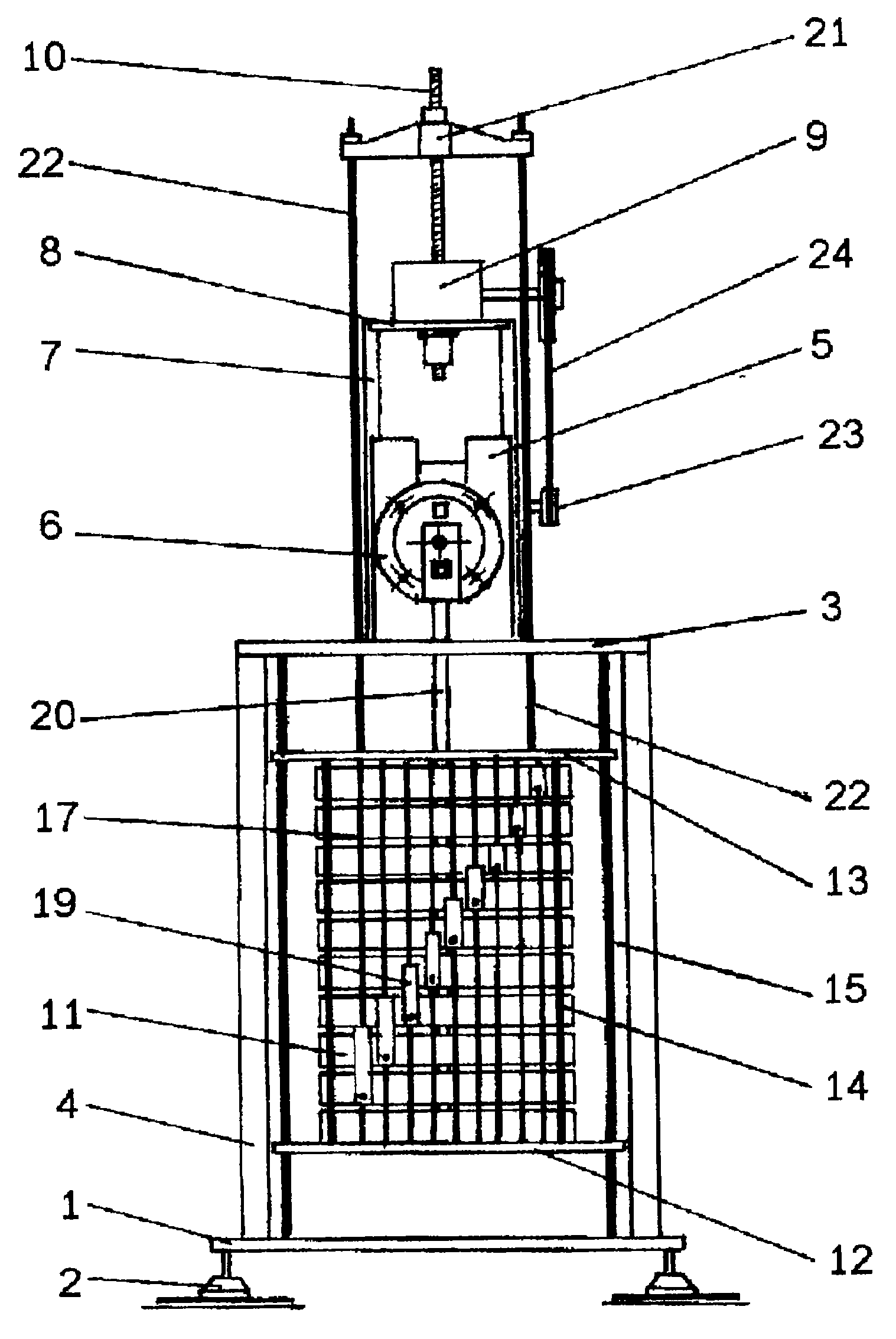
Сущность заявляемого устройства поясняется примером его реализации и графическими материалами. На фиг.1 представлен общий вид устройства; на фиг.2 представлен вертикальный разрез контейнера с образцовыми грузами.The essence of the claimed device is illustrated by an example of its implementation and graphic materials. Figure 1 presents a General view of the device; figure 2 presents a vertical section of a container with exemplary goods.
Устройство для контроля силоизмерительных датчиков содержит станину, которая содержит нижнюю опорную плиту 1, снабженную регулировочными опорами 2, например, винтовыми, и верхнюю опорную плиту 3, соединенную жестко с нижней плитой колоннами 4. На верхней опорной плите установлен узел 5 для закрепления контролируемых датчиков 6. Узел 5 может быть выполнен в виде плиты с соответствующими посадочными гнездами и средствами фиксации, выбранными из числа известных. На верхней плите установлены стойки 7, соединенные траверсой 8, на которой установлен червячный механизм 9 с силовым винтом 10. Внутри станины размещен контейнер с набором образцовых грузов-дисков 11. Контейнер выполнен в виде нижнего 12 и верхнего 13 фланцев, жестко соединенных между собой стяжками 14. Для обеспечения строго вертикального перемещения контейнера в процессе нагружения через его фланцы пропущены направляющие стержни 15, концы которых закреплены в опорных плитах. Все диски, кроме нижнего.The device for monitoring load sensors contains a bed, which contains a lower base plate 1, equipped with adjusting supports 2, for example, screw, and an upper base plate 3, rigidly connected to the lower plate columns 4. On the upper base plate mounted node 5 for fixing the monitored sensors 6 The node 5 can be made in the form of a plate with the corresponding landing sockets and means of fixation, selected from among the known. On the upper plate, racks 7 are connected, connected by a traverse 8, on which a worm gear 9 with a power screw 10 is installed. Inside the frame there is a container with a set of model cargo disks 11. The container is made in the form of lower 12 and upper 13 flanges rigidly connected to each other by ties 14. To ensure strictly vertical movement of the container during loading, guide rods 15 are passed through its flanges, the ends of which are fixed in the base plates. All drives except the bottom.
снабжены выступами 16 и подвешены внутри контейнера на захватах 17с лапками 18. Захваты снабжены юстировочными устройствами 19, например, в виде винтовой пары, позволяющими регулировать высоту расположения лапок. При этом лапки захватов смещены относительно друг друга по образующей дисков с образованием винтовой линии, чтобы на перемещение одного диска не оказывали влияние другие. Нижний груз-диск соединен тягой 20 с контролируемым датчиком. Контейнер с дисками связан с силовым винтом с помощью коромысла 21 и подвесов 22, закрепленных на верхнем фланце контейнера. Вращение червяка червячного механизма осуществляется от электромеханического привода 23 с клиноременной передачей 24. Устройство снабжено известными средствами регистрации, которые на чертеже не показаны.equipped with protrusions 16 and suspended inside the container on the grippers 17 with legs 18. The grips are equipped with adjustment devices 19, for example, in the form of a screw pair, allowing you to adjust the height of the legs. In this case, the claw legs are displaced relative to each other along the generatrix of the disks with the formation of a helix so that others do not affect the movement of one disk. The lower load-disk is connected by a rod 20 with a controlled sensor. The container with the disks is connected to the power screw using the rocker arm 21 and suspensions 22 mounted on the upper flange of the container. The rotation of the worm of the worm mechanism is carried out from an electromechanical drive 23 with a V-belt drive 24. The device is equipped with known recording means, which are not shown in the drawing.
В частных случаях устройство снабжается известным омметром (не показан), один вывод которого соединяют с нижним грузом непосредственно или через конструктивные элементы установки, а второй - с контейнером. При этом с помощью известных средств изолируют: электрически нижний диск от контейнера.In special cases, the device is equipped with a known ohmmeter (not shown), one output of which is connected to the lower load directly or through the structural elements of the installation, and the second to the container. At the same time, using known means, they isolate: electrically the lower disk from the container.
Устройство используют следующим образом. Выполняют подготовительные работы, заключающиеся в следующем. Устанавливают в контейнере грузы 11, при этом нижний диск с тягой 20 укладывают на нижний фланец 12 контейнера, а остальные подвешивают на захватах 17 путем размещения выступов 16 на лапках 18. Затем с помощью регулировочных опор 2 и известных средств контроля (уровня или отвеса) устанавливают станину так, чтобы ее опорные плиты были строго горизонтальны. Затем с помощью юстировочных устройств 19 приводят диски в строго горизонтальное положение и устанавливают одинаковые зазоры между ними. После проведения подготовительных работ в узле 5 закрепляют контролируемый силоизмерительный датчик 6, например, в виде металлического тела с наклеенными на нем тензорезисторами. С датчиком соединяют тягу 20 с помощью известных средств, включают средства регистрации и привод 23. Червячный механизм 9, взаимодействуя с силовым винтом 10, обеспечивает перемещение коромысла 21 и связанного с ним с помощью подвесов 22 контейнера вниз. Контейнер перемещаясь вниз нижним фланцем 12 выходит из контакта с нижним грузомдиском 11 и силоизмерительный датчик 6 через тягу 20 нагружается этим грузом. Реакция датчика на нагрузку определяется с помощью регистрирующего устройства. Затем, по мере продвижения контейнера вниз, а значит и захватов 17 с лапками 18, с нижним грузом сближается находящийся выше него груз-диск 11, укладывается на него, и выступы 16 выходят из контакта с лапками 18, и таким образом создается вторая ступень нагружения, реакция датчика на которую регистрируется. И далее, по мере перемещения контейнера вниз, на нижний диск будут последовательно укладываться диск за диском, создавая последующие ступени нагружения.The device is used as follows. Perform preparatory work, consisting in the following. Weights 11 are installed in the container, while the lower disk with the thrust 20 is laid on the lower flange 12 of the container, and the rest are hung on the grippers 17 by placing the protrusions 16 on the legs 18. Then, using the adjusting supports 2 and known means of control (level or plumb), they are installed the bed so that its base plates are strictly horizontal. Then, using the adjustment devices 19, the disks are brought into a strictly horizontal position and the same gaps between them are set. After carrying out preparatory work in node 5, a controlled load cell 6 is fixed, for example, in the form of a metal body with strain gauges glued on it. A rod 20 is connected to the sensor using known means, includes recording means and a drive 23. The worm gear 9, interacting with the power screw 10, moves the beam 21 and the container connected with it by means of suspensions 22 downward. The container moving downward with the lower flange 12 comes out of contact with the lower load disk 11 and the load sensor 6 through the rod 20 is loaded with this load. The response of the sensor to the load is determined using a recording device. Then, as the container moves down, and hence the grippers 17 with the legs 18, the load-disk 11 located above it is brought closer to it and placed on it, and the protrusions 16 come out of contact with the legs 18, and thus a second loading stage is created the sensor response to which is recorded. And further, as the container moves down, disk by disk will be sequentially stacked on the lower disk, creating subsequent loading steps.
В процессе нагружения осуществляется наблюдение за показаниями омметра. Он должен показывать разрыв цепи, т.е. бесконечно большое сопротивление. Если показания его изменятся, то это означает, что какой-то из дисков, создающих в данный момент нагрузку на контролируемый датчик, контактирует с контейнером, что создает погрешность в работе устройства. В этом случае процесс нагружения прекращают и устраняют возникший контакт груза с контейнером.During loading, an ohmmeter is monitored. It should show an open circuit, i.e. infinitely great resistance. If its readings change, this means that some of the disks that are currently creating a load on the monitored sensor is in contact with the container, which creates an error in the operation of the device. In this case, the loading process is stopped and the resulting contact of the cargo with the container is eliminated.
Предлагаемое устройство позволяет контролировать, калибровать и поверять силоизмерительные датчики любых типов и видов. Для перехода от одного типа к другому достаточно изменить конструкцию узла крепления датчика и подобрать соответствующие средства регистрации реакции датчика па нафузку.The proposed device allows you to control, calibrate and verify load cells of any type and type. To switch from one type to another, it is enough to change the design of the sensor attachment unit and select the appropriate means of recording the sensor response to the flange.
Claims (5)
Priority Applications (1)
| Application Number | Priority Date | Filing Date | Title |
|---|---|---|---|
| RU2000110612/20U RU15934U1 (en) | 2000-05-03 | 2000-05-03 | DEVICE FOR MONITORING POWER SENSORS |
Applications Claiming Priority (1)
| Application Number | Priority Date | Filing Date | Title |
|---|---|---|---|
| RU2000110612/20U RU15934U1 (en) | 2000-05-03 | 2000-05-03 | DEVICE FOR MONITORING POWER SENSORS |
Publications (1)
| Publication Number | Publication Date |
|---|---|
| RU15934U1 true RU15934U1 (en) | 2000-11-20 |
Family
ID=48276519
Family Applications (1)
| Application Number | Title | Priority Date | Filing Date |
|---|---|---|---|
| RU2000110612/20U RU15934U1 (en) | 2000-05-03 | 2000-05-03 | DEVICE FOR MONITORING POWER SENSORS |
Country Status (1)
| Country | Link |
|---|---|
| RU (1) | RU15934U1 (en) |
-
2000
- 2000-05-03 RU RU2000110612/20U patent/RU15934U1/en active
Similar Documents
| Publication | Publication Date | Title |
|---|---|---|
| CN106769422B (en) | Circumferential distributed high-flux durable creep testing machine | |
| JP2001153749A (en) | Load cell inspection device | |
| CN110487479A (en) | A torque sensor detection device and method | |
| CN106679786A (en) | Verification device of static weight and superposition composite hook scale | |
| CN109752176B (en) | Self-balancing tilting and swinging test bed | |
| CN103542977A (en) | Full-automatic electromagnetic balance-type small-force-value standard device | |
| RU15934U1 (en) | DEVICE FOR MONITORING POWER SENSORS | |
| CN207850524U (en) | A kind of nested type electronic crane scale counterweight loading system | |
| CN213336447U (en) | Automatic loading device for weight loading | |
| JP3767324B2 (en) | Large bedrock testing equipment | |
| CN214471198U (en) | Fluid quantitative metering device | |
| CN111238722A (en) | Dead weight type force standard machine and force value correction method thereof | |
| JP5669116B1 (en) | Weighing device with verification function and verification weighing method | |
| JP2001133376A (en) | Force calibrating mechanism for hardness testing machine and force calibrating method for hardness testing machine | |
| CN215727378U (en) | Concrete temperature and humidity measuring device under constant axial tension effect | |
| CN117647353A (en) | Tension sensor calibrating device | |
| CN108020312A (en) | A kind of nested type electronic crane scale counterweight loading system | |
| CN212379218U (en) | A cyclic concrete material and component impact tester | |
| CN212568413U (en) | A lever loading mechanism and engineering wood creep testing device | |
| CN118275037A (en) | Gravity balance device and static test device | |
| CN112197848A (en) | An automatic loading device for weight loading | |
| CN112763047A (en) | Discrimination threshold verification mechanism for static weight/superposition combined type hook scale verification device | |
| JPS5861440A (en) | Loading type automatic consolidation tester | |
| JPH11108740A (en) | Load cell-type weighing device equipped with calibration function | |
| JPH1164146A (en) | Torque calibration device |