RU151663U1 - RADAR SITUATION SIMULATOR WITH RADIO TECHNICAL SIGNALS SYNTHESIS - Google Patents
RADAR SITUATION SIMULATOR WITH RADIO TECHNICAL SIGNALS SYNTHESIS Download PDFInfo
- Publication number
- RU151663U1 RU151663U1 RU2014134491/07U RU2014134491U RU151663U1 RU 151663 U1 RU151663 U1 RU 151663U1 RU 2014134491/07 U RU2014134491/07 U RU 2014134491/07U RU 2014134491 U RU2014134491 U RU 2014134491U RU 151663 U1 RU151663 U1 RU 151663U1
- Authority
- RU
- Russia
- Prior art keywords
- signal
- krlk
- signals
- radar
- fed
- Prior art date
Links
- 230000015572 biosynthetic process Effects 0.000 title claims abstract description 18
- 238000003786 synthesis reaction Methods 0.000 title claims abstract description 10
- 238000012544 monitoring process Methods 0.000 claims abstract description 7
- 238000002955 isolation Methods 0.000 claims abstract description 5
- 238000001914 filtration Methods 0.000 claims description 3
- 238000012545 processing Methods 0.000 claims description 3
- 238000006243 chemical reaction Methods 0.000 claims description 2
- 238000005755 formation reaction Methods 0.000 description 7
- XLYOFNOQVPJJNP-UHFFFAOYSA-N water Substances O XLYOFNOQVPJJNP-UHFFFAOYSA-N 0.000 description 5
- 238000010586 diagram Methods 0.000 description 4
- 238000004088 simulation Methods 0.000 description 4
- 241001070947 Fagus Species 0.000 description 3
- 235000010099 Fagus sylvatica Nutrition 0.000 description 3
- 239000006185 dispersion Substances 0.000 description 3
- 238000012007 large scale cell culture Methods 0.000 description 3
- 230000002238 attenuated effect Effects 0.000 description 2
- 238000005516 engineering process Methods 0.000 description 2
- 238000013507 mapping Methods 0.000 description 2
- 238000012549 training Methods 0.000 description 2
- 244000309464 bull Species 0.000 description 1
- 238000004891 communication Methods 0.000 description 1
- 230000003750 conditioning effect Effects 0.000 description 1
- 238000013461 design Methods 0.000 description 1
- 230000002452 interceptive effect Effects 0.000 description 1
- 238000004519 manufacturing process Methods 0.000 description 1
- 239000000463 material Substances 0.000 description 1
- 238000001556 precipitation Methods 0.000 description 1
- 238000001228 spectrum Methods 0.000 description 1
- 230000001360 synchronised effect Effects 0.000 description 1
Images

Landscapes
- Radar Systems Or Details Thereof (AREA)
Abstract
Полезная модель относится к учебно-техническим средствам и устройствам радиолокации и может быть использована для обучения и тренировки операторов корабельных радиолокационных комплексов (КРЛК), как в штатных условиях на корабле с использованием антенны КРЛК, так и в условиях учебного центра без использования антенны КРЛК, с имитацией радиолокационной обстановки (РЛО), адекватной реальным условиям, и позволяет повысить навыки личного состава КРЛК.The utility model relates to educational and technical means and devices of radar and can be used to train and train operators of shipborne radar systems (KRLK), both under normal conditions on a ship using a KRLK antenna, and in a training center without a KRLK antenna, with imitation of a radar situation (RLO), adequate to real conditions, and allows you to improve the skills of personnel KRLK.
Сущность полезной модели заключается в том, что в имитаторе РЛО с синтезатором сигналов радиотехнических средств (ССРТС), содержащем блок управления, контроля и индикации (БУКИ) и сумматор, в состав дополнительно введены блок гальванической развязки (БГР), блок умножения частоты (БУЧ), линия цифрового синтеза частоты (ЛЦСЧ), цифро-аналоговый преобразователь (ЦАП), дифференциальный усилитель (ДУ) и фильтр низких частот (ФНЧ), а также упомянутый ССРТС. The essence of the utility model lies in the fact that in the RLO simulator with a radio signal synthesizer (SSRTS), which contains a control, monitoring and display unit (BUKI) and an adder, a galvanic isolation unit (BGR) and a frequency multiplication unit (BEUCH) are additionally introduced into the composition , a line for digital frequency synthesis (LCC), a digital-to-analog converter (DAC), a differential amplifier (DU) and a low-pass filter (LPF), as well as the aforementioned SSRTS.
Description
Полезная модель относится к учебно-техническим средствам и устройствам радиолокации и может быть использована для обучения и тренировки операторов корабельных радиолокационных комплексов (КРЛК), как в штатных условиях на корабле с использованием антенны КРЛК, так и в условиях учебного центра без использования антенны КРЛК, с имитацией радиолокационной обстановки (РЛО), адекватной реальным условиям, и позволяет повысить навыки личного состава КРЛК.The utility model relates to educational and technical means and devices of radar and can be used to train and train operators of shipborne radar systems (KRLK), both under normal conditions on a ship using a KRLK antenna, and in a training center without a KRLK antenna, with imitation of a radar situation (RLO), adequate to real conditions, and allows you to improve the skills of personnel KRLK.
Известен имитатор радиолокационной обстановки по патенту РФ на полезную модель №52196, 2005 г., МПК G01S 7/40, опубл. Бюл. №7, 2006 г., содержащий блок управления, радиолокатор, первый и второй генераторы промежуточной частоты, первый и второй электронные ключи и сумматор, при этом выходы первого и второго генераторов соединены с первыми входами первого и второго электронных ключей, управляющие входы которых соединены с первым и вторым выходами блока управления соответственно, а их (ключей) вторые выходы - с первым и вторым входами сумматора соответственно, выход сумматора соединен с входом радиолокатора, первый выход которого соединен с первым входом блока управления, а его (радиолокатора) второй выход - со вторым входом блока управления.Known simulator of the radar situation according to the patent of the Russian Federation for utility model No. 52196, 2005, IPC G01S 7/40, publ. Bull. No. 7, 2006, comprising a control unit, a radar, first and second intermediate frequency generators, first and second electronic keys and an adder, wherein the outputs of the first and second generators are connected to the first inputs of the first and second electronic keys, the control inputs of which are connected to the first and second outputs of the control unit, respectively, and their (keys) second outputs with the first and second inputs of the adder, respectively, the output of the adder is connected to the input of the radar, the first output of which is connected to the first input of the control unit phenomenon, and it (radar) of the second output - to a second input of the control unit.
Известный прибор обеспечивает имитацию радиосигналов, посредством штатной антенны КРЛК как от движущихся, так и от неподвижных целей, но имеет недостатки:The known device provides an imitation of radio signals through a standard antenna KRLK both from moving and from stationary targets, but has the disadvantages:
- малая функциональность из-за невозможности имитации параметров более двух движущихся целей, например траектории движения, скорости, типа и эффективной площади рассеивания цели, различных климатических условий, состояния водной поверхности;- low functionality due to the impossibility of simulating the parameters of more than two moving targets, for example, the trajectory of movement, speed, type and effective area of dispersion of the target, various climatic conditions, and the state of the water surface;
- невозможность работы без использования антенны КРЛК, например в условиях испытательного центра, из-за отсутствия автономного синтезатора сигналов радиотехнических средств (ССРТС).- the inability to work without using the antenna KRLK, for example in a test center, due to the lack of an autonomous synthesizer of signals of radio equipment (SSRTS).
Решаемой задачей является расширение функциональных возможностей путем обеспечения имитации различных климатических условий (температура, ветер, осадки и т.д.) и состояние водной поверхности (волнение, боковая и килевая качка, подводные течения и т.д.), а также путем использования ССРТС для имитации суммарных сигналов от радиотехнических средств (РТС) с навигационной обстановкой и имитируемыми целями на фоне активных и пассивных помех.The problem to be solved is the expansion of functionality by providing simulations of various climatic conditions (temperature, wind, precipitation, etc.) and the state of the water surface (waves, lateral and keel pitching, underwater currents, etc.), as well as by using SSRTS to simulate the total signals from radio equipment (RTS) with a navigational environment and simulated targets against active and passive interference.
Существующие приборы подобной конструкции позволяют имитировать цели только для простых импульсных радиолокационных станций, поскольку использование всего двух аппаратных каналов не позволяет производить одновременную имитацию более двух целей с одного элемента дистанции, одна из которых неподвижна, с нулевой доплеровской скоростью, а вторая - подвижная, имитируемая доплеровским смещением частоты, а также отсутствует возможность динамического изменения смещения доплеровской частоты, поэтому у всех имитируемых подвижных целей должна быть одна и та же скорость и все они должны приближаться или удаляться. Кроме того, не предусмотрена возможность имитации радиолокационных объектов в станциях со сложным законом изменения амплитуды или фазы зондирующего сигнала, а также не реализована имитация окружающейобстановки, например береговой черты, буев, мостов и прочих объектов, получаемых с использованием картографической информации, параметров подвижных целей - траектории движения, скорости, типа и эффективной площади рассеивания (ЭПР) и различных климатических условий, состояния водной поверхности и т.п., кроме того, в известных приборах отсутствует режим автономной имитации сигналов РТС для тренировки операторов КРЛК, например, в условиях учебного центра.Existing devices of this design allow you to simulate targets only for simple pulsed radar stations, since the use of only two hardware channels does not allow simultaneous simulation of more than two targets from one distance element, one of which is stationary, with zero Doppler speed, and the second is mobile, simulated by Doppler frequency shift, and there is also no possibility of dynamically changing the Doppler frequency shift, therefore, for all simulated moving targets, to be the same speed and all of them should be approaching or moving away. In addition, it is not possible to simulate radar objects in stations with a complex law of changing the amplitude or phase of the sounding signal, and it does not imitate the surrounding environment, such as a coastline, buoys, bridges and other objects obtained using cartographic information, parameters of moving targets - trajectories movement, speed, type and effective area of dispersion (EPR) and various climatic conditions, the state of the water surface, etc., in addition, in the known devices are absent There is a mode of autonomous simulation of RTS signals for training KRLK operators, for example, in a training center.
Для реализации поставленной задачи целесообразно обучение и тренировку операторов производить как в штатных условиях работы на корабле с использованием антенны КРЛК и созданием условий, при которых оператор не видит разницы между реальными и имитируемыми сигналами на пульте управления, так и на берегу, например в учебном центре, посредством пассивного канала берегового (учебного) радиолокационного комплекса (БРЛК) и ССРТС, с созданием условий при которых оператор видит картину полной имитации сигналов от РТС и погодную обстановку.To achieve this goal, it is advisable to educate and train operators both under normal conditions of work on the ship using the KRLK antenna and creating conditions under which the operator does not see the difference between real and simulated signals on the control panel, and on the shore, for example, in a training center, by means of a passive channel of the coastal (training) radar complex (BRLK) and SSRTS, with the creation of conditions under which the operator sees a picture of a complete simulation of signals from the RTS and weather conditions.
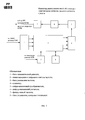
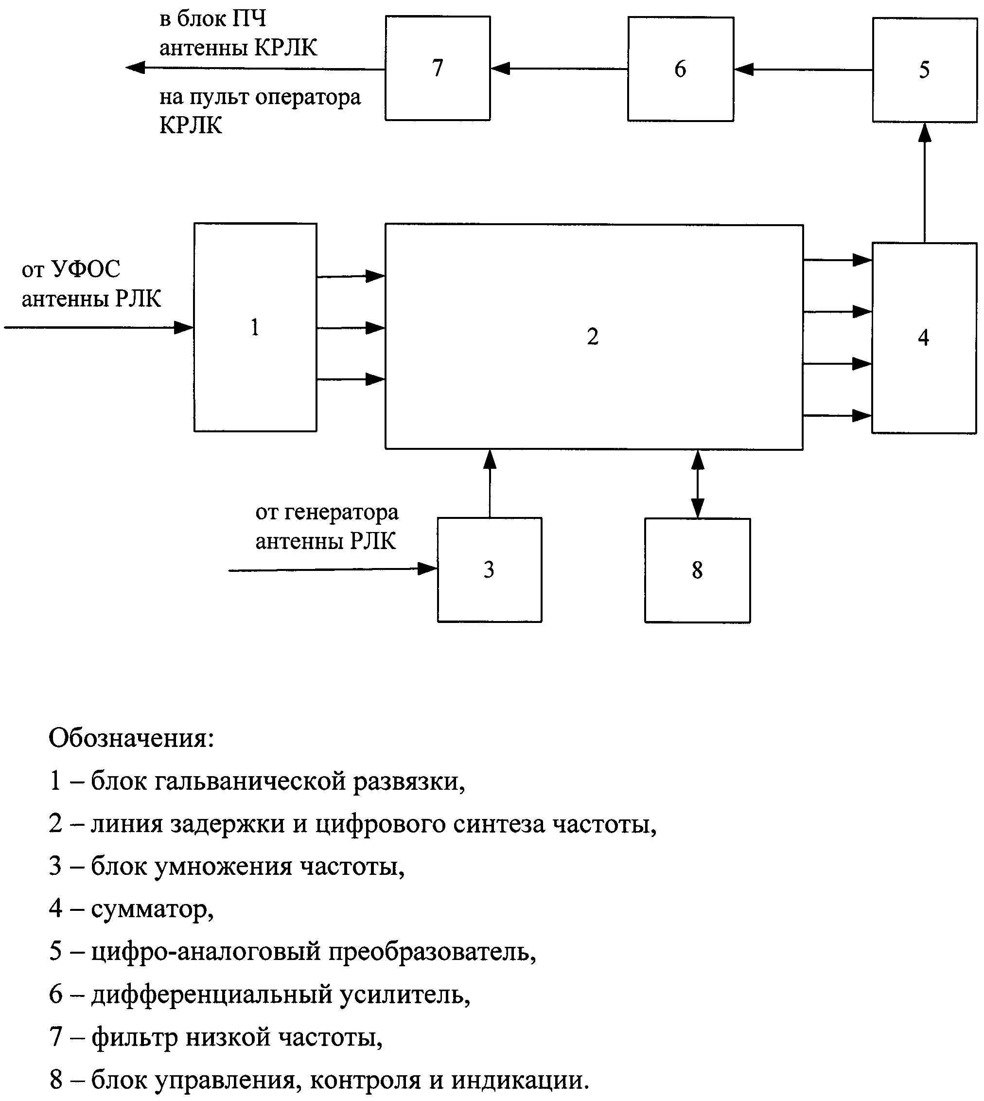
Сущность полезной модели заключается в том, что в имитаторе РЛО с ССРТС, содержащим блок управления, контроля и индикации (БУКИ) и сумматор, отличающийся тем, что в состав введены блок гальванической развязки (БГР), блок умножения частоты (БУЧ), линия цифрового синтеза частоты (ЛЦСЧ), цифро-аналоговый преобразователь (ЦАП), дифференциальный усилитель (ДУ) и фильтр низких частот (ФНЧ), а также упомянутый синтезатор сигналов радиотехнических средств (ССРТС), при этом в штатном режиме работы корабельного радиолокационного комплекса (КРЛК) сигналы от устройства формирования и обработки сигналов (УФОС) приемника через антенну КРЛК поступают на входы БГР, где происходит гальваническая развязка сигналов, с выходов БГР сигналы поступают в ЛЦСЧ, одновременно с генератора передатчика через антенну КРЛК сигнал опорной частоты поступает на вход БУЧ, где происходит преобразование сигнала частоты, и далее в упомянутую ЛЦСЧ, где совместно с сигналами от УФОС и БГР формируются радиолокационные отклики, с выходов ЛЦСЧ преобразованные сигналы поступают на входы сумматора, где они объединяются в общий сигнал на промежуточной частоте (ПЧ), с выхода сумматора общий сигнал поступает на вход ЦАП, в котором формируется дифференциальный аналоговый сигнал (ДАС), затем ДАС поступает в ДУ, где усиливается, и далее - в ФНЧ для фильтрации, после чего обработанный сигнал поступает на вход блока ПЧ приемника через антенну КРЛК, где реальный сигнал подменяется на сигнал с реальной навигационной обстановкой и имитируемыми целями на фоне активных и пассивных помех для отображения на пульте оператора КРЛК, кроме того, в режиме автономной работы пассивного канала берегового радиолокационного комплекса (БРЛК) имитируемые сигналы радиотехнических средств (РТС) от ССРТС поступают на приемник БРЛК, где реальный сигнал подменяется на суммарный сигнал от РТС с синтезированными навигационной обстановкой и целями на фоне активных и пассивных помех для отображения на пульте оператора БРЛК, причем в обоих режимах работы управление и контроль формирования радиолокационных сигналов и их индикация (отображение) осуществляется БУКИ.The essence of the utility model lies in the fact that in the RLO simulator with SSRTS, containing a control, monitoring and display unit (BUKI) and an adder, characterized in that the unit includes a galvanic isolation unit (BGR), a frequency multiplication unit (BEUCH), a digital line frequency synthesis (LCC), a digital-to-analog converter (DAC), a differential amplifier (DU) and a low-pass filter (LPF), as well as the aforementioned signal synthesizer of radio equipment (SSRTS), while in the normal mode of operation of a ship's radar system (KRLK) signals from the signal generating and processing device (UFOS) of the receiver, through the KRLK antenna, they are fed to the inputs of the BGR, where the signals are galvanically decoupled, the signals from the BGR outputs are fed to the LCC, at the same time from the transmitter generator, through the KRLK antenna, the reference frequency signal is fed to the BEACH input, where the conversion occurs frequency signal, and then to the aforementioned LCCC, where, together with signals from UFOS and BGR, radar responses are generated, from the outputs of the LCCC, the converted signals are fed to the inputs of the adder, where they are combined into a common signal at an intermediate frequency (IF), from the output of the adder, the general signal is fed to the input of the DAC, in which a differential analog signal (DAS) is generated, then the DAS is fed to the remote control, where it is amplified, and then to the low-pass filter for filtering, after which it is processed the signal is fed to the input of the receiver IF unit through the KRLK antenna, where the real signal is replaced by a signal with a real navigation situation and simulated targets against the background of active and passive interference for display on the KRLK operator’s console, in addition, in stand-alone operation of the active channel of the coastal radar complex (RLS), the simulated signals of radio equipment (RTS) from the SSRTS are sent to the receiver of the RLS, where the real signal is replaced by the total signal from the RTS with synthesized navigation conditions and targets against the background of active and passive interference for display on the operator’s panel of the RRL moreover, in both modes of operation, control and monitoring of the formation of radar signals and their indication (display) is carried out by BUKI.
Сущность полезной модели поясняется структурными схемами на фиг. 1 изображена схема работы имитатора в штатном режиме работы антенны КРЛК, на фиг. 2 - схема работы имитатора в режиме автономной работы пассивного канала берегового БРЛК с ССРТС, на схемах приняты следующие обозначения:The essence of the utility model is illustrated by the structural diagrams in FIG. 1 shows a diagram of the simulator in the normal mode of operation of the KRLK antenna, FIG. 2 - diagram of the simulator in stand-alone operation of the passive channel of the coastal radar station with SSRTS, the following notation is used in the diagrams:
1 - блок гальванической развязки (БГР),1 - block galvanic isolation (BGR),
2 - линия цифрового синтеза частоты (ЛЦСЧ),2 - line digital frequency synthesis (LSCS),
3 - блок умножения частоты (БУЧ),3 - block frequency multiplication (BEECH),
4 - сумматор,4 - adder
5 - цифро-аналоговый преобразователь (ЦАП),5 - digital-to-analog converter (DAC),
6 - дифференциальный усилитель (ДУ),6 - differential amplifier (DU),
7 - фильтр низкой частоты (ФНЧ),7 - low-pass filter (low-pass filter),
8 - блок управления, контроля и индикации (БУКИ),8 - control unit, control and indication (BUKI),
9 - синтезатор сигналов радиотехнических средств (ССРТС).9 - a signal synthesizer for radio equipment (SSRTS).
Работа на имитаторе радиолокационной обстановки (ИРЛО) с ССРТС осуществляется следующим образом.Work on the simulator of the radar situation (IRLO) with SSRTS is as follows.
Создают упражнение на ИРЛО из заранее сформированного списка, путем выбора района плавания. Для создания нового района плавания с помощью средств ввода-вывода ИРЛО определяют географические координаты границ района, после чего от корабельного карт-сервера (ККС) запрошенная катрографическая информация поступает в ИРЛО. Сформированный на основании поступившей информации район плавания в виде цифровой базы хранится в энергонезависимой памяти ИРЛО. Далее задают радиолокационную обстановку с учетом района плавания и радиолокационной наблюдаемости, надводные цели и траектории их движения. Для каждой имитированной цели задают координаты - пеленг, дистанцию и курс, тип (выбирают из списка), параметры маневра и скорость цели, а также уровень активных и пассивных помех - уровень баллов взволнованной водной поверхности, гидрометеорологические образования, перемещающиеся в заданном направлении, береговую черту, навигационные ориентиры фарватеров (вехи, буи, бакены и т.д.), информация о которых поступает от ККС.По введенным данным ИРЛО формирует имитированный эхо-сигнал на промежуточной частоте (ПЧ) от надводных целей и навигационных ориентиров на фоне собственного шума приемника, активных и пассивных помех.Create an exercise for IRLO from a pre-formed list, by choosing a navigation area. To create a new navigation area using the IRLO input-output means, the geographic coordinates of the region’s borders are determined, after which the requested cathographic information is received from the ship’s map server (KKS) to the IRLO. Formed on the basis of the received information, the navigation area in the form of a digital base is stored in the non-volatile memory of the IRLO. Next, a radar situation is set taking into account the navigation area and radar observability, surface targets and their trajectories. For each simulated target, coordinates are set - bearing, distance and course, type (selected from the list), maneuver parameters and target speed, as well as the level of active and passive interference - the level of points of the excited water surface, hydrometeorological formations moving in a given direction, the coastline , navigational landmarks of the fairways (milestones, buoys, beacons, etc.), information about which comes from the KKS. According to the entered data, the IRLO generates a simulated echo signal at an intermediate frequency (IF) from surface targets and navigation reference points against the background of the receiver's own noise, active and passive interference.
При имитации радиолокационного объекта также генерируются сообщения об имитируемых текущих характеристиках собственного движения носителя, например корабля и направления антенны активного канала КРЛК, и передаются на пульт оператора, за которым находится обучаемый.When simulating a radar object, messages are also generated about the simulated current characteristics of the carrier’s own movement, for example, a ship and the direction of the antenna of the active KRLK channel, and transmitted to the operator’s console, behind which the student is located.
В штатном режиме работы с использованием антенны КРЛК сигналы амплитудной и частотной модуляции от устройства формирования и обработки сигналов (УФОС) приемника через антенну КРЛК поступают на входы БГР 1, где происходит гальваническая развязка сигналов, с выходов БГР 1 сигналы поступают в ЛЦСЧ 2, одновременно с генератора передатчика через антенну КРЛК сигнал опорной частоты (ОЧ) поступает на вход БУЧ 3, где происходит умножение сигнала ОЧ в несколько раз, и далее в упомянутую ЛЦСЧ 2, где, совместно с сигналами модуляции от УФОС и БГР 1 формируются радиолокационные отклики в полной разрядной сетке и аттенюирутся в соответствии с установленными значениями эффективной площади рассеивания (ЭПР) и удаленности от КРЛК и складываются на промежуточной частоте (ПЧ), с выходов ЛЦСЧ 2 преобразованные сигналы поступают на входы сумматора 4, где они объединяются в общий сигнал на ПЧ, с выхода сумматора общий сигнал поступает на вход ЦАП 5, в котором формируется дифференциальный аналоговый сигнал (ДАС), затем ДАС поступает в ДУ 6, где усиливается, и далее - в ФНЧ 7 для фильтрации, после чего синтезированный сигнал поступает на вход блока ПЧ приемника через антенну КРЛК, где реальный сигнал подменяется на сигнал с реальной навигационной обстановкой и имитируемыми целями на фоне активных и пассивных помех для отображения на рабочем пульте оператора КРЛК, причем управление и контроль формирования радиолокационных откликов и их индикация (отображение) осуществляется БУКИ 8.In normal operation using the KRLK antenna, the amplitude and frequency modulation signals from the signal conditioning and processing device (UFOS) of the receiver through the KRLK antenna are fed to the inputs of the
В режиме автономной работы с использованием пассивного канала БРЛК и ССРТС 9 задают РТС, например радиолокационную станцию с пассивной (принимающей) антенной пассивного канала упомянутого БРЛК, и параметры их работы, посредством БУКИ 8, имитируемые сигналы от синтезатора 9 поступают на приемник БРЛК, где реальный сигнал подменяется на суммарный имитируемый сигнал с навигационной обстановкой и имитируемыми целями на фоне активных и пассивных помех для отображения на пульте оператора БРЛК, причем управление и контроль формирования радиолокационных откликов и их индикация (отображение) осуществляется БУКИ 8.In the autonomous mode of operation using the passive channel BRLK and SSRTS 9, the RTS are set, for example, a radar station with a passive (receiving) antenna of the passive channel of the said BRLK, and the parameters of their operation, by the BUKI 8, the simulated signals from the
При этом синтезатор 9 обеспечивает формирование несущей частоты сигналов РТС посредством прямого цифрового синтеза с применением независимой амплитудной модуляцией (AM), частотной модуляцией (ЧМ) и фазовой модуляцией (ФМ) закрывающих весь спектр используемых сигналов РТС: линейно-частотная модуляцию буев, высотомеров и т.п., импульсные и фазоманипулированные сигналы активного радиоканала, квадратурную амплитудную модуляцию, множественный доступ с кодовым разделением, квадратурную фазовую модуляцию и т.п.сигналов систем связи, кроме того, синтезатор 9 обеспечивает независимое формирование до 1024 сигналов РТС с произвольными пространственным расположением источника и его интенсивностью, с выхода синтезатора 9 сигнал являющийся суммой сигналов всех РТС с учетом углового положения приемной антенны, а также положения источников сигналов поступает в приемник БРЛК и на пульт оператора БРЛК, причем управление синтезатором 9, а именно законом изменения ЧМ, ФМ, AM, мощностью источника и его расположением осуществляется БУКИ 8.In this case, the
В конкретном случае ЛЦСЧ 2 выполнена в виде 4-10 (в зависимости от количества имитируемых параметров радиолокационной обстановки) цифровых вычислительных синтезаторов (ЦВС) в виде микросхем 150ПЛ8Т (DDS - Direct Digital Synthesizers - прямой цифровой синтез частоты).In a specific case, LSCC 2 is made in the form of 4-10 (depending on the number of simulated parameters of the radar situation) digital computer synthesizers (CVS) in the form of 150PL8T microcircuits (DDS - Direct Digital Synthesizers - direct digital frequency synthesis).
Технические характеристики ЦВС описаны на сайте ОАО НПЦ «Элвис» (124460, г. Москва, г. Зеленоград, пр. 4922, южная промзона, стр. 2.) http://multicore.ru => синтезаторы частот (DDS, PLL) => цифровой вычислительный синтезатор 150ПЛ8Т (DDS).The technical characteristics of the DAC are described on the site of the Elvis Scientific and Production Center OJSC (124460, Moscow, Zelenograd, pr. 4922, southern industrial zone, p. 2.) http://multicore.ru => frequency synthesizers (DDS, PLL) => digital computer synthesizer 150PL8T (DDS).
Принцип действия ЦВС описан в Свободной энциклопедии «Википедия» - «Цифровой вычислительный синтезатор».The principle of the operation of the DAC is described in the Free Wikipedia Encyclopedia - Digital Computing Synthesizer.
Подробное описание прямого цифрового синтеза частоты опубликовано в журнале «Компоненты и технологии» №7, 2001 г. Леонид Ридико «DDS: прямой цифровой синтез частоты».A detailed description of direct digital frequency synthesis is published in the journal Components and Technologies No. 7, 2001 by Leonid Ridiko “DDS: Direct Digital Frequency Synthesis”.
Технический результат от использования полезной модели заключается в расширении функциональных возможностей путем обеспечения формирования имитированных эхо-сигналов на ПЧ от надводных целей и навигационных ориентиров на фоне собственного шума приемника, активных помех (несинхронных и хаотически импульсных помех от радиоэлектронных средств, работающих в Х-диапазоне радиоволн) и пассивных помех (взволнованная водная поверхность, гидрометеорологические образования, береговая черта, навигационные ориентиры фарватеров), отображения карты района действия, интерактивного размещения целей на этой карте, координаты целей, ЭПР, типа целей, различных вариантов маневра и независимой скорости целей, при этом количество имитируемых целей может составлять не менее 128 на азимут как в штатном режиме работы на корабле с использованием антенны КРЛК, так и в автономном режиме работы на берегу, например, в учебном центре, посредством пассивного канала БРЛК и ССРТСThe technical result from the use of the utility model is to expand the functionality by providing the formation of simulated echo signals on the inverter from surface targets and navigation landmarks against the background of the receiver’s own noise, active interference (non-synchronous and randomly pulsed interference from electronic devices operating in the X-band of radio waves ) and passive interference (agitated water surface, hydrometeorological formations, coastline, navigational directions of the fairways), display artifacts of the area of operation, interactive placement of targets on this map, target coordinates, EPR, type of targets, various options for maneuver and independent speed of targets, while the number of simulated targets can be at least 128 per azimuth as in normal operation on a ship using the KRLK antenna , and in stand-alone mode of operation on the shore, for example, in a training center, through a passive channel BRLK and SSRTS
Указанный технический результат достигается совокупностью отличительных признаков, а именно дополнительным введением в состав заявляемого имитатора радиолокационной обстановки (ИРЛО) блока гальванической развязки (БГР), блока умножения частоты (БУЧ), линии цифрового синтеза частоты (ЛЦСЧ), цифро-аналогового преобразователя (ЦАП), дифференциального усилителя (ДУ), фильтра низких частот (ФНЧ) и устройства функционального контроля (УФК), а также синтезатора сигналов радиотехнических средств (ССРТС).The specified technical result is achieved by a set of distinctive features, namely the additional introduction of the galvanic isolation unit (BGR), the frequency multiplication unit (BEUCH), the digital frequency synthesis line (LCC), the digital-to-analog converter (DAC) into the inventive simulator of the radar situation (IRL) , a differential amplifier (DU), a low-pass filter (LPF) and a functional control device (UFC), as well as a radio signal synthesizer (SSRTS).
Представленные описание и схема заявляемого ИРЛО, используя известные в приборостроении материалы, технологии и покупные изделия, позволяют изготовить его промышленным способом и использовать для обучения и тренировки операторов КРЛК с имитацией радиолокационной обстановки, адекватной реальным условиям, с целью повышения навыков и боеготовности личного состава КРЛК, как с использованием штатной антенны КРЛК, так и с использованием пассивного канала БРЛК и ССРТС.The presented description and scheme of the claimed IRLO, using materials, technologies and purchased products known in instrumentation, make it possible to manufacture it industrially and use it to train and train KRLK operators with a simulated radar situation that is adequate to real conditions, in order to increase the skills and combat readiness of KRLK personnel, both using a standard KRLK antenna and using a passive BRRLK and SSRTS channel.
Claims (1)
Priority Applications (1)
| Application Number | Priority Date | Filing Date | Title |
|---|---|---|---|
| RU2014134491/07U RU151663U1 (en) | 2014-08-22 | 2014-08-22 | RADAR SITUATION SIMULATOR WITH RADIO TECHNICAL SIGNALS SYNTHESIS |
Applications Claiming Priority (1)
| Application Number | Priority Date | Filing Date | Title |
|---|---|---|---|
| RU2014134491/07U RU151663U1 (en) | 2014-08-22 | 2014-08-22 | RADAR SITUATION SIMULATOR WITH RADIO TECHNICAL SIGNALS SYNTHESIS |
Publications (1)
| Publication Number | Publication Date |
|---|---|
| RU151663U1 true RU151663U1 (en) | 2015-04-10 |
Family
ID=53297073
Family Applications (1)
| Application Number | Title | Priority Date | Filing Date |
|---|---|---|---|
| RU2014134491/07U RU151663U1 (en) | 2014-08-22 | 2014-08-22 | RADAR SITUATION SIMULATOR WITH RADIO TECHNICAL SIGNALS SYNTHESIS |
Country Status (1)
| Country | Link |
|---|---|
| RU (1) | RU151663U1 (en) |
Cited By (3)
| Publication number | Priority date | Publication date | Assignee | Title |
|---|---|---|---|---|
| RU2687071C1 (en) * | 2018-09-07 | 2019-05-07 | Федеральное государственное унитарное предприятие "Государственный научно-исследовательский институт авиационных систем" (ФГУП "ГосНИИАС") | Spatial radar signal simulator |
| RU2760601C1 (en) * | 2020-12-14 | 2021-11-29 | Акционерное общество «Научно-производственное предприятие «Калужский приборостроительный завод «Тайфун» | Training complex for training operators of onshore facilities |
| CN116343553A (en) * | 2023-03-16 | 2023-06-27 | 无锡天路科技有限公司 | A radar target simulator and its control method |
-
2014
- 2014-08-22 RU RU2014134491/07U patent/RU151663U1/en not_active IP Right Cessation
Cited By (3)
| Publication number | Priority date | Publication date | Assignee | Title |
|---|---|---|---|---|
| RU2687071C1 (en) * | 2018-09-07 | 2019-05-07 | Федеральное государственное унитарное предприятие "Государственный научно-исследовательский институт авиационных систем" (ФГУП "ГосНИИАС") | Spatial radar signal simulator |
| RU2760601C1 (en) * | 2020-12-14 | 2021-11-29 | Акционерное общество «Научно-производственное предприятие «Калужский приборостроительный завод «Тайфун» | Training complex for training operators of onshore facilities |
| CN116343553A (en) * | 2023-03-16 | 2023-06-27 | 无锡天路科技有限公司 | A radar target simulator and its control method |
Similar Documents
| Publication | Publication Date | Title |
|---|---|---|
| US9397761B2 (en) | RF signal generating device | |
| CN104614713B (en) | A kind of ship that is suitable for carries the radar echo signal simulator of radar system | |
| CN102830407B (en) | Method and system for automatically testing anti-interference performance of Beidou receiver | |
| US11210517B2 (en) | Technologies for acting based on object detection | |
| CN203930058U (en) | A kind of synthetic-aperture radar Area Objects Echo Signal Simulator | |
| US10803210B2 (en) | Real-time electromagnetic environmental simulator | |
| CN108919210A (en) | A kind of one-dimensional phase sweeps three-dimensional radar intermediate frequency target simulator | |
| RU151663U1 (en) | RADAR SITUATION SIMULATOR WITH RADIO TECHNICAL SIGNALS SYNTHESIS | |
| KR101534167B1 (en) | Apparatus for analysing real time jamming effectiveness of Satellite Navigation | |
| Frissell et al. | Heliophysics and amateur radio: citizen science collaborations for atmospheric, ionospheric, and space physics research and operations | |
| RU2691295C2 (en) | Global radiohydroacoustic system of monitoring fields of atmosphere, ocean and earth crust in the marine environment and determining formation sources thereof | |
| RU2530544C1 (en) | Method for simulation of signal reflected from ground surface in real beam mapping mode | |
| KR101227913B1 (en) | Jamming signal generating system linked with gps simulator | |
| RU134668U1 (en) | SIMULATOR OF RADAR SITUATION OF A SHIP RADAR COMPLEX WITH A FUNCTIONAL CONTROL DEVICE | |
| Carrano et al. | Wave-optics analysis of HF propagation through traveling ionospheric disturbances and developing plasma bubbles | |
| RU132599U1 (en) | SIMULATOR OF THE OPERATOR OF THE RADAR COMPLEX | |
| EP2997678B1 (en) | Rf signal generating device | |
| RU2624607C1 (en) | Method of acoustic tomography system fields in the atmosphere, the oceans and crust of different physical nature in the marine environment | |
| RU2691294C2 (en) | Method for forming and application of global radiohydroacoustic system of monitoring atmospheric, oceanic and crustal fields in marine environment and recognition of sources thereof | |
| KR101227911B1 (en) | Simulation signal generating system for localization of jammer | |
| Nickisch | Practical applications of Haselgrove's equations for HF systems | |
| Handayani et al. | Design and development of the FMCW Radar Scene Generator | |
| CN116609742A (en) | SAR echo simulation and interference assessment method and system based on real-time map inversion | |
| Nickisch et al. | Feasibility study for reconstructing the spatial-temporal structure of TIDs from high-resolution backscatter ionograms | |
| Hu et al. | Electromagnetic Environment and Target Simulator for Radar Test |
Legal Events
| Date | Code | Title | Description |
|---|---|---|---|
| MM1K | Utility model has become invalid (non-payment of fees) |
Effective date: 20150823 |