RU149408U1 - DEVICE FOR OPERATIONAL ULTRASONIC RAIL HEAD CONTROL - Google Patents
DEVICE FOR OPERATIONAL ULTRASONIC RAIL HEAD CONTROL Download PDFInfo
- Publication number
- RU149408U1 RU149408U1 RU2014105313/28U RU2014105313U RU149408U1 RU 149408 U1 RU149408 U1 RU 149408U1 RU 2014105313/28 U RU2014105313/28 U RU 2014105313/28U RU 2014105313 U RU2014105313 U RU 2014105313U RU 149408 U1 RU149408 U1 RU 149408U1
- Authority
- RU
- Russia
- Prior art keywords
- transducers
- rail
- receiving
- radiating
- emitting
- Prior art date
Links
Images


Abstract
1. Устройство для ультразвукового контроля головки рельса, содержащее блок электроакустических преобразователей и техническое средство для пространственного позиционирования данных преобразователей, в котором указанный блок включает в себя два преобразователя, выполненных с возможностью наклонного ввода/приема ультразвука, первый из которых является излучающим или излучающим/приемным, а второй приемным, отличающееся тем, что средство для позиционирования выполнено с возможностью размещения преобразователей со стороны боковой рабочей грани головки рельса так, чтобы сгенерированная излучающим преобразователем УЗ волна отразилась от дефекта, затем от противоположной нерабочей грани рельса и была принята приемным преобразователем.2. Устройство по п.1, в котором угол ввода ультразвука составляет 1÷50° по отношению к нормали, а угол приема лежит в диапазоне 20÷50°.3. Устройство по п.1, в котором преобразователи выполнены и размещены с возможностью акустической связи по схеме тандем.4. Устройство по п.1, содержащее до пяти приемных преобразователей.5. Устройство по п.4, в котором расстояние между излучающим или излучающим/приемным преобразователем и приемными преобразователями составляет 3÷150 мм.6. Устройство по п.1, характеризующееся габаритными размерами для свободного прохождения конструктивных элементов рельсового пути, включая стрелки.1. Device for ultrasonic monitoring of the rail head, comprising a block of electro-acoustic transducers and technical means for spatial positioning of these transducers, in which said block includes two transducers configured to tilt ultrasound input / receive, the first of which is emitting or emitting / receiving and a second receiving one, characterized in that the positioning means is arranged to accommodate the transducers from the side slave side whose head face of the rail so that the generated ultrasonic transducer emits a wave reflected from the defect, and then from the opposite verge broken rail and was admitted receiving preobrazovatelem.2. The device according to claim 1, in which the input angle of ultrasound is 1 ÷ 50 ° with respect to the normal, and the reception angle lies in the range of 20 ÷ 50 °. 3. The device according to claim 1, in which the transducers are made and placed with the possibility of acoustic communication according to the tandem scheme. The device according to claim 1, containing up to five receiving converters. The device according to claim 4, in which the distance between the radiating or radiating / receiving transducer and the receiving transducers is 3 ÷ 150 mm. The device according to claim 1, characterized by overall dimensions for the free passage of structural elements of the rail track, including arrows.
Description
Устройство для эксплуатационного ультразвукового контроля головки рельсаDevice for operational ultrasonic monitoring of the rail head
Полезная модель относится к средствам для ультразвукового контроля (УЗК) протяженных рельсовых путей в процессе их эксплуатации, в частности, железнодорожных рельсов, а также рельсов, предназначенных для движения городского подвижного состава. Кроме того, настоящее техническое решение может найти применение при контроле иных металлических объектов, в частности, различных изделий листового, сортового и фасонного проката в случаях, когда требуется высокая достоверность УЗК при сложных условиях контроля.The utility model relates to means for ultrasonic testing (UZK) of long rail tracks during their operation, in particular, railway rails, as well as rails intended for the movement of urban rolling stock. In addition, this technical solution can find application in the control of other metal objects, in particular, various products of sheet, long and shaped steel in cases where high reliability of ultrasonic testing is required under difficult control conditions.
Качество рельсовых путей должно быть подтверждено в процессе их эксплуатации, поэтому эксплуатационный контроль рельсовых путей предполагает проведение исследования по всей длине уже уложенных рельсов. Однако проведение контроля при этом оказывается затруднено как из-за произошедших при эксплуатации рельсов изменений, так и из-за конструктивных особенностей рельсового пути (стрелки, переезды и пр.), затрудняющих доступ к объекту контроля.The quality of the rail tracks must be confirmed during their operation, therefore, operational monitoring of the rail tracks involves a study along the entire length of the already laid rails. However, the control at the same time is difficult both due to changes that occurred during the operation of the rails, and because of the design features of the rail track (arrows, crossings, etc.) that impede access to the control object.
Большое значение имеет контроль головки рельса, так как именно данная часть рельса является наиболее нагруженной, подвергается интенсивному износу и склонна к разрушению. К категории самых опасных и трудновыявляемых внутренних дефектов относят поперечные и продольно-наклонные трещины, способные привести к хрупкому излому рельса под проходящим поездом.Of great importance is the control of the rail head, since it is this particular part of the rail that is the most loaded, undergoes intensive wear and is prone to destruction. The category of the most dangerous and difficult to detect internal defects include transverse and longitudinally inclined cracks that can lead to a brittle fracture of the rail under a passing train.
Известен ряд различных устройств, предназначенных для УЗК головки рельса.A number of different devices are known for ultrasonic testing of the rail head.
Устройство по патентному документу US 7849748 В2 содержит блок электроакустических преобразователей и техническое средство для его позиционирования со стороны поверхности катания. Однако поверхностные дефекты в данной области головки рельса и подповерхностные горизонтальные расслоения становятся непреодолимой преградой при попытках контроля внутренних дефектов известным устройством.The device according to patent document US 7849748 B2 contains a block of electro-acoustic transducers and technical means for its positioning from the side of the rolling surface. However, surface defects in a given region of the rail head and subsurface horizontal delaminations become an insurmountable obstacle when trying to control internal defects by a known device.
УЗК головки рельса на наличие поперечных трещин, замаскированных поверхностными дефектами и подповерхностными расслоениями, способно проводить устройство по патентному документу JP 2000-009698 А. Известное устройство содержит электроакустические преобразователи, размещаемые с обеих боковых сторон головки рельса. Однако у реального железнодорожного полотна на всем протяжении нити рельсов доступна только внутренняя, называемая рабочей, часть боковой поверхности головки рельса, так как именно с данной стороны проходят реборды колес. Перемещение элементов устройства для контроля со стороны наружной части оказывается практически невозможным, в частности, при пересечении стрелок и переездов. По этой причине не возможно эффективное применение известного устройства для эксплуатационного УЗК реального рельсового пути. На практике область использования известного устройства ограничена контролем новых или демонтированных после вывода из эксплуатации рельсов.The ultrasonic inspection of the rail head for the presence of transverse cracks masked by surface defects and subsurface delaminations is capable of carrying out the device according to patent document JP 2000-009698 A. The known device comprises electro-acoustic transducers placed on both sides of the rail head. However, in a real railway track, only the inside, called the working, part of the side surface of the rail head is accessible over the entire length of the rails, since it is from this side that the wheel flanges pass. The movement of the elements of the device for control from the outside is practically impossible, in particular, at the intersection of arrows and crossings. For this reason, it is not possible to effectively use the known device for operational ultrasonic testing of a real rail track. In practice, the scope of use of the known device is limited to monitoring new or dismantled rails after decommissioning.
Наиболее близким аналогом заявленного устройства для УЗК головки рельса является устройство, известное из патентного документа RU 23987 U1. Устройство содержит блок электроакустических преобразователей и техническое средство для позиционирования данных преобразователей. При этом указанный блок включает в себя два преобразователя, первый из которых является излучающим или излучающим/приемным, а второй приемным. Однако в известном устройстве измерительные преобразователи размещают со стороны катания головки рельса, что не позволяет достичь необходимой достоверности УЗК в реальных условиях из-за влияния на результаты УЗК качества поверхности катания рельсов и подповерхностных отслоений металла.The closest analogue of the claimed device for ultrasonic testing of the rail head is a device known from patent document RU 23987 U1. The device contains a block of electro-acoustic transducers and technical means for positioning these transducers. Moreover, this unit includes two converters, the first of which is emitting or emitting / receiving, and the second receiving. However, in the known device, the measuring transducers are placed on the side of the rail head, which does not allow to achieve the necessary reliability of ultrasonic testing in real conditions due to the influence on the results of ultrasonic testing of the quality of the rolling surface of the rails and subsurface exfoliation of the metal.
Задачей является повышение достоверности эксплуатационного УЗК рельсов.The objective is to increase the reliability of operational ultrasonic testing of rails.
Обеспечиваемый настоящей полезной моделью технический результат заключается в исключении влияния на результаты эксплуатационного УЗК рельсового пути, имеющего ограниченный доступ к нерабочей части боковой поверхности головки рельса, качества поверхности катания рельсов и подповерхностных отслоений металла.The technical result provided by this useful model is to exclude the influence on the results of the operational ultrasonic testing of the rail track having limited access to the non-working part of the side surface of the rail head, the quality of the rolling surface of the rails and subsurface metal detachments.
Указанный технический результат достигается благодаря тому, что в устройстве для УЗК головки рельса, содержащем блок электроакустических преобразователей и техническое средство для пространственного позиционирования данных преобразователей, в котором указанный блок содержит два преобразователя, выполненных с возможностью наклонного ввода/приема ультразвука, первый из которых является излучающим или излучающим/приемным, а второй приемным, средство для позиционирования выполнено с возможностью размещения преобразователей со стороны боковой рабочей грани головки рельса так, чтобы сгенерированная излучающим преобразователем УЗ волна отразилась от дефекта, затем от противоположной нерабочей грани рельса и была принята приемным преобразователем.The specified technical result is achieved due to the fact that in the device for ultrasonic testing of the rail head containing a block of electro-acoustic transducers and technical means for spatial positioning of these transducers, in which said block contains two transducers made with the possibility of inclined ultrasound input / reception, the first of which is emitting or emitting / receiving, and the second receiving, the means for positioning is arranged to accommodate the transducers from the side lateral working face of the rail head so that the ultrasonic wave generated by the radiating transducer is reflected from the defect, then from the opposite non-working rail face and is received by the receiving transducer.
В частном случае угол ввода ультразвука составляет 1÷50° по отношению к нормали, а угол приема лежит в диапазоне 20÷50°.In a particular case, the angle of ultrasound input is 1 ÷ 50 ° with respect to the normal, and the reception angle lies in the range of 20 ÷ 50 °.
В другом частном случае преобразователи выполнены и размещены с возможностью акустической связи по схеме тандем.In another particular case, the transducers are made and placed with the possibility of acoustic communication according to the tandem scheme.
В еще одном частном случае устройство содержит до пяти приемных преобразователей. Причем расстояние между излучающим или излучающим/приемным преобразователем и приемными преобразователями составляет 3÷150 мм.In another particular case, the device contains up to five receiving converters. Moreover, the distance between the radiating or radiating / receiving transducer and receiving transducers is 3 ÷ 150 mm.
Также в частном случае устройство характеризуется габаритными размерами для свободного прохождения конструктивных элементов рельсового пути, включая стрелки.Also in the particular case, the device is characterized by overall dimensions for the free passage of structural elements of the rail track, including arrows.
Полезная модель поясняется следующими графическими материалами.The utility model is illustrated by the following graphic materials.
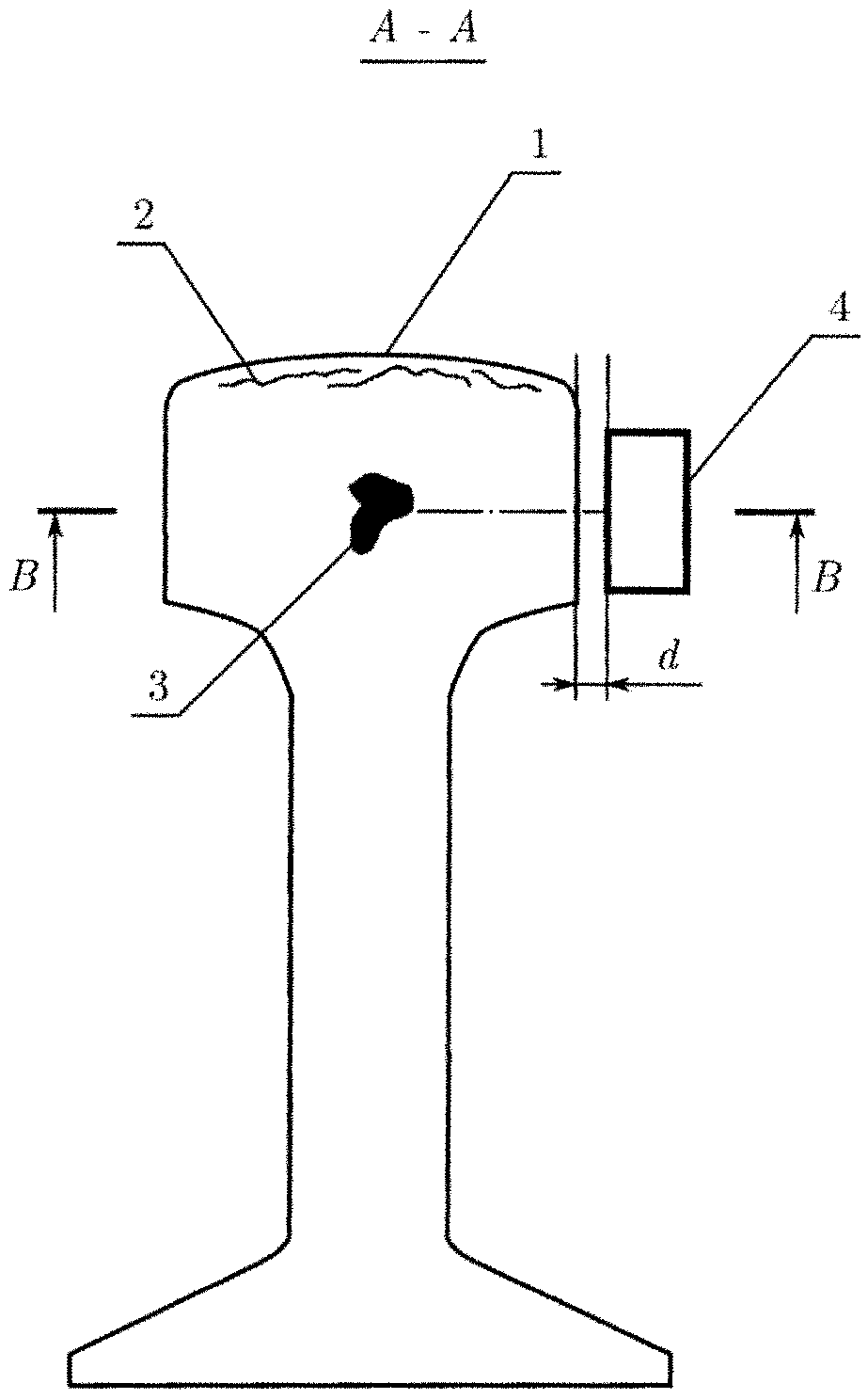
Фиг. 1: схема размещения блока электроакустических преобразователей на контролируемом рельсе, вид на рельс в поперечном разрезе.FIG. 1: arrangement of a block of electro-acoustic transducers on a controlled rail, view of the rail in cross section.
Фиг. 2: фрагмент рельса и схема размещения электроакустических преобразователей, вид сверху (внутренний дефект вблизи блока преобразователей).FIG. 2: rail fragment and arrangement of electro-acoustic transducers, top view (internal defect near the transducer block).
Фиг. 3: фрагмент рельса и схема размещения электроакустических преобразователей, вид сверху (внутренний дефект в центре головки рельса).FIG. 3: rail fragment and arrangement of electro-acoustic transducers, top view (internal defect in the center of the rail head).
Фиг. 4: фрагмент рельса и схема размещения электроакустических преобразователей, вид сверху (дефект находится в наиболее удаленной части головки рельса, а поверхность дефекта повернута под небольшим углом к поперечной плоскости).FIG. 4: fragment of the rail and the arrangement of electro-acoustic transducers, top view (the defect is in the most remote part of the rail head, and the surface of the defect is rotated at a slight angle to the transverse plane).
Фиг. 5: фрагмент рельса и блок электроакустических преобразователей, вид со стороны боковой поверхности рельса.FIG. 5: fragment of the rail and the block of electro-acoustic transducers, view from the side of the side surface of the rail.
Головка 1 рельса имеет две рабочие поверхности: верхнюю поверхность катания и боковую поверхность (грань) со стороны прохождения реборд колес, обычно внутреннюю, обращенную к противоположному рельсу; противоположная грань головки рельса является нерабочей (Грицык В.И. Дефекты рельсов железнодорожного пути. М., 2005, с. 6). Доступ к рабочим поверхностям обеспечен на всем протяжении полотна, что важно для эксплуатационного контроля, так как в противном случае колеса подвижного состава не смогут свободно перемещаться. Поверхность катания воспринимает основные нагрузки от колес проходящих составов. В результате возникают дефекты в виде микротрещин, выкрашивания, следов от пробуксовки колес, а также локальных горизонтальных расслоений 2, частично или полностью препятствующих вводу УЗ колебаний вглубь головки 1 и маскирующих таким образом сигналы от критичных внутренних дефектов в головке 1 рельса, что затрудняет их обнаружение, вплоть до полной невозможности контроля. Однако именно внутри головки 1 зарождаются опасные поперечные трещины 3, способные привести к хрупкому излому рельса. Таким образом, без выявления внутренних поперечных трещин 3 УЗК рельсов не может считаться достоверным.The
Осуществление полезной модели показано на следующем примере предпочтительной реализации.The implementation of the utility model is shown in the following example of a preferred implementation.
Устройство для УЗК головки 1 рельса содержит блок 4, под которым понимается совокупность функционально объединенных электромагнитно-акустических преобразователей (ЭМАП) 5-8. Число ЭМАП определяется числом их активных элементов-индукторов (в том числе, составных). ЭМАП 5-8 расположены один за другим в ряд таким образом, чтобы УЗ волна, сгенерированная излучающим ЭМАП 5, отразилась от дефекта 3, затем от противоположной нерабочей грани рельса и была принята одним из приемников (ЭМАП 6-8). При этом ЭМАП 5-8 образуют так называемую схему тандем, являющуюся частным случаем зеркального эхо-метода (Алешин Н.П., Белый В.Е., Вопилкин Α.X. и др. Методы акустического контроля металлов. - М.: Машиностроение, 1989. - С.95, 155). Так как приемных ЭМАП 6-8 при этом больше одного, то данная схема может быть названа мультитандемной. Расстояние между излучающим или излучающим/приемным ЭМАП 5 и приемным ЭМАП 6 составляет 150 мм, а расстояние между ЭМАП 5 и приемным ЭМАП 8 равно 3 мм. Для реализации схемы тандем ЭМАП 5-8 выполнены с возможностью наклонного ввода/приема УЗ. Угол излучения (ввода) УЗ составляет 1÷50° по отношению к нормали, а угол приема лежит в диапазоне 20÷50°.The device for ultrasonic testing of the
Также устройство содержит техническое средство для пространственного позиционирования ЭМАП 5-8 блока 4 и образования указанной мультитандемной схемы прозвучивания со стороны боковой рабочей грани головки 1 рельса. Техническое средство для позиционирования включает в себя датчики, направляющие, приводы и каретки для перемещения установленных на подвижных кронштейнах ЭМАП 5-8 в горизонтальной и вертикальной плоскостях, а также для изменения при необходимости углов между данными ЭМАП и поверхностью или продольной осью рельса, величины воздушного зазора d между ними, благодаря чему обеспечивается возможность размещения указанных ЭМАП 5-8 со стороны боковой рабочей грани головки 1 рельса и поддержания величины зазора d между преобразователями и гранью головки 1 рельса при перемещении блока 4 вдоль нити рельсов.The device also contains technical means for spatial positioning of the EMAT 5-8 of
Блок 4 и техническое средство для позиционирования ЭМАП связаны с общим устройством управления и обработки данных.
Возможны конфигурации устройства с двумя и более излучающими преобразователями 5 или с двумя и более блоками 4, расположенными с той же боковой стороны головки 1 рельса, что и в базовом варианте. Также целесообразно дополнение устройства измерительным каналом для прозвучивания головки 1 рельса со стороны катания. При этом преобразователи блоков 4 установлены в пересекающихся перпендикулярных плоскостях. Конструкция технического средства для позиционирования ЭМАП 5-8 верхнего блока 4 имеет необходимое число элементов, обеспечивающих возможность размещения ЭМАП 5-8 верхнего блока 4 со стороны поверхности катания головки 1 рельса и поддержания требуемой величины воздушного зазора между ними при осуществлении контроля на скорости. Все блоки 4 и техническое средство для позиционирования ЭМАП связаны с общим устройством управления и обработки данных, обеспечивающим как независимое, так и совместное функционирование блоков 4.Device configurations are possible with two or more
В общем случае конструкция технического средства для пространственного позиционирования ЭМАП предусматривает возможность для установки нескольких уровней датчиков для послойного сканирования и определения расположения дефекта, размеров и глубины залегания, а также для несения иного оборудования, в частности, для контроля шейки и подошвы рельса.In the general case, the design of the technical means for spatial positioning of the EMAT provides for the possibility of installing several levels of sensors for layer-by-layer scanning and determining the location of the defect, size and depth, as well as for carrying other equipment, in particular, for monitoring the neck and sole of the rail.
Для одновременного контроля обеих нитей рельсов пару устройств размещают, например, в вагоне-дефектоскопе, в котором находится остальное необходимое оборудование. При этом габаритные размеры устройства достаточны для свободного прохождения сложных конструктивных элементов рельсового пути, включая стрелки, по всей длине участка контроля.For simultaneous monitoring of both strands of rails, a pair of devices are placed, for example, in a flaw detector car, in which the rest of the necessary equipment is located. Moreover, the overall dimensions of the device are sufficient for the free passage of complex structural elements of the rail track, including arrows, along the entire length of the control section.
Устройство работает следующим образом.The device operates as follows.
ЭМАП 5-8 подводят к боковой рабочей грани головки 1 рельса и устанавливают необходимую величину воздушного зазора d, которую затем поддерживают в приемлемом диапазоне. Вагон-дефектоскоп приводят в движение, перемещая таким образом устройств вдоль нити рельсов, и осуществляют контроль. При этом ЭМАП 5 возбуждает в головке 1 рельса УЗ колебания в виде распространяющихся упругих волн. Если устройство приближается ко внутреннему дефекту в виде поперечной трещины 3, то УЗ волна сначала отражается от трещины 3, а затем от противоположной стенки головки 1 рельса, после чего попадает на соответствующий приемный ЭМАП, измерительный сигнал с которого передают в устройство для обработки данных.EMAP 5-8 lead to the lateral working face of the
Исключение влияния на результаты эксплуатационного УЗК рельсового пути, имеющего ограниченный доступ к нерабочей части боковой поверхности головки рельса, качества поверхности катания рельсов и подповерхностных отслоений металла возможно при одновременном выполнении двух условий: а) прозвучивание проводят со стороны боковой грани головки 1 рельса зеркальным эхо-методом, б) указанная грань является рабочей. Оба условия удовлетворяются при выполнении средства для позиционирования с возможностью размещения ЭМАП 5-8 со стороны боковой рабочей грани головки 1 рельса так, чтобы сгенерированная ЭМАП 5 УЗ волна отразилась от дефекта, затем от противоположной нерабочей грани рельса и была принята ЭМАП 6-8. При этом со стороны нерабочей грани головки 1 рельса преобразователи полностью отсутствуют.The exclusion of the influence on the results of operational ultrasonic testing of the rail track with limited access to the non-working part of the side surface of the rail head, the quality of the rolling surface of the rails and subsurface exfoliation of the metal is possible if two conditions are fulfilled simultaneously: a) sounding is carried out from the side of the side of the
Так как все ЭМАП являются преобразователями бесконтактного типа, отсутствует необходимость в каком-либо улучшении области акустического контакта, в частности, не требуется применение контактных жидкостей и очистка поверхности рельсов даже от небольших загрязнений, как в случае пьезоэлектрических преобразователей, что делает возможным работу устройства в условиях низких температур. Рабочая поверхность преобразователя не истирается от контакта с рельсом, что положительно сказывается на достоверности УЗК.Since all EMATs are non-contact type transducers, there is no need for any improvement in the acoustic contact area, in particular, contact liquids and surface cleaning of the rails even from small impurities are not required, as in the case of piezoelectric transducers, which makes it possible to operate the device under low temperatures. The working surface of the converter is not abraded by contact with the rail, which positively affects the reliability of ultrasonic testing.
Измерения посредством ЭМАП характеризуются малой величиной погрешности и стабильностью сигнала на скорости в силу того, что отсутствует прохождение сигнала через большое число промежуточных сред (в случае контактного пьезоэлектрического преобразователя УЗ волна возбуждается в пьезопластине, затем проходит через призму с определенным углом, затем через протектор, затем через контактную среду и только потом входит в объект контроля). Так как прозвучивание осуществляют со стороны боковой рабочей грани, то внутренние дефекты не маскируются дефектами поверхности катания (фиг. 1).EMAT measurements are characterized by a small error and signal stability at speed due to the fact that there is no signal passing through a large number of intermediate media (in the case of a contact piezoelectric transducer, the ultrasound wave is excited in the piezoelectric plate, then passes through a prism with a certain angle, then through the tread, then through the contact medium and only then enters the control object). Since sounding is carried out from the side of the lateral working face, internal defects are not masked by defects in the skating surface (Fig. 1).
Благодаря ряду приемных ЭМАП 6-8 устройство является широкозахватным. При помощи ЭМАП 8 выявляют дефекты вблизи от поверхности рабочей грани, а при помощи ЭМАП 6 - наиболее удаленные, около противоположной грани головки 1 рельса. Расстояние между преобразователями от 3 до 150 мм оптимально для контроля головки 1 рельса по всей ее толщине. Область захвата еще больше увеличивается при выполнении ЭМАП 5 не только излучающим, но и приемным. В отличие от известной схемы тандем с единственным приемником возможно выявление внутренних дефектов на всей глубине головки 1 рельса (фиг. 2-4), что также повышает достоверность УЗК.Thanks to a number of receiving EMAT 6-8, the device is wide-spread. Using
В случаях, если трещина 3 строго перпендикулярна продольной оси рельса, то угол ввода УЗ излучения равен углу приема (фиг. 2-3). Если трещина 3 ориентирована иначе, то указанные углы не равны между собой (фиг.4), что позволяет определять ориентацию дефекта и повышать достоверность УЗК.In cases where the
Кроме того, если дефект выходит на поверхность объекта контроля, образуя таким образом уголковый отражатель, возможна работа по эхо-методу, когда излучающий преобразователь 5 непосредственно принимает сигнал от данного дефекта.In addition, if the defect comes to the surface of the test object, thus forming an angular reflector, it is possible to work by the echo method when the emitting
Использование нескольких излучающих ЭМАП 5 и/или блоков 4, в том числе с разной направленностью (например приемник, расположенный со стороны поверхности катания принимает акустический сигнал, сгенерированный излучателем со стороны боковой рабочей грани, или наоборот), нескольких уровней датчиков для послойного сканирования и определения расположения дефекта, размеров и глубины залегания, а также иного оборудования, в частности, для контроля шейки и подошвы рельса, позволяет получить дополнительный объем измерительной информации для повышения достоверности УЗК. Кроме того, повышается надежность и производительность контроля.The use of several emitting
Claims (6)
Priority Applications (1)
| Application Number | Priority Date | Filing Date | Title |
|---|---|---|---|
| RU2014105313/28U RU149408U1 (en) | 2014-02-13 | 2014-02-13 | DEVICE FOR OPERATIONAL ULTRASONIC RAIL HEAD CONTROL |
Applications Claiming Priority (1)
| Application Number | Priority Date | Filing Date | Title |
|---|---|---|---|
| RU2014105313/28U RU149408U1 (en) | 2014-02-13 | 2014-02-13 | DEVICE FOR OPERATIONAL ULTRASONIC RAIL HEAD CONTROL |
Publications (1)
| Publication Number | Publication Date |
|---|---|
| RU149408U1 true RU149408U1 (en) | 2014-12-27 |
Family
ID=53291931
Family Applications (1)
| Application Number | Title | Priority Date | Filing Date |
|---|---|---|---|
| RU2014105313/28U RU149408U1 (en) | 2014-02-13 | 2014-02-13 | DEVICE FOR OPERATIONAL ULTRASONIC RAIL HEAD CONTROL |
Country Status (1)
| Country | Link |
|---|---|
| RU (1) | RU149408U1 (en) |
-
2014
- 2014-02-13 RU RU2014105313/28U patent/RU149408U1/en active
Similar Documents
| Publication | Publication Date | Title |
|---|---|---|
| EP1565738B1 (en) | Laser-air hybrid ultrasonic technique for non-contact testing of railroad tracks | |
| US9950715B2 (en) | Air-coupled ultrasonic inspection of rails | |
| US7555954B2 (en) | In-track wheel inspection system | |
| CN106770657A (en) | For the detection method that subway tunnel railway roadbed comes to nothing | |
| RU2353924C1 (en) | Method for ultrasonic testing of rail base | |
| RU2308027C1 (en) | Method of ultrasonic test of rail head | |
| RU2645818C1 (en) | Method for ultrasonic inspection of rail bases | |
| US10766510B1 (en) | Method and apparatus for detecting defects located in the head area of rail | |
| RU2433397C1 (en) | Method for complete ultrasonic inspection of rail bases | |
| RU2184374C1 (en) | Ultrasonic method for controlling rail head | |
| WO2018101860A1 (en) | Method for ultrasonically inspecting an aluminothermically welded rail joint | |
| RU149408U1 (en) | DEVICE FOR OPERATIONAL ULTRASONIC RAIL HEAD CONTROL | |
| RU2613574C1 (en) | Method for ultrasound detection of microcracks on operating railhead fillet | |
| RU2652511C1 (en) | Method of micro cracks on the rail head rolling surface ultrasonic detection | |
| JP2009058238A (en) | Method and device for defect inspection | |
| RU2184960C1 (en) | Process of ultrasonic inspection of rail head | |
| KR20130048874A (en) | Nondestructive sightseeing device of trackage's head | |
| WO2017030458A1 (en) | Ultrasonic diagnostics of vertically-oriented defects in prismatic metal products | |
| RU2783753C1 (en) | Ultrasonic method for detecting defects in the rail head | |
| RU2585304C1 (en) | Transverse-longitudinal method for implementation of echo-ranging method for ultrasonic inspection of articles along whole section | |
| Fadaeifard et al. | Rail inspection technique employing advanced nondestructive testing and Structural Health Monitoring (SHM) approaches—A review | |
| RU2785302C1 (en) | Ultrasonic method for assessing defects in the rail head and determining the profile of the tread surface | |
| RU2299428C1 (en) | Device for ultrasound flaw detection of railroad rails | |
| RU2442152C1 (en) | Echoscopic method for ultrasonic quality control of the product across the entire section | |
| RU126141U1 (en) | DEVICE OF ULTRASONIC CONTROL OF HEAD AND NECK OF RAILS |