RU148293U1 - SMOKING PRODUCT WITH MULTI-SECTION FILTER - Google Patents
SMOKING PRODUCT WITH MULTI-SECTION FILTER Download PDFInfo
- Publication number
- RU148293U1 RU148293U1 RU2014122922/12U RU2014122922U RU148293U1 RU 148293 U1 RU148293 U1 RU 148293U1 RU 2014122922/12 U RU2014122922/12 U RU 2014122922/12U RU 2014122922 U RU2014122922 U RU 2014122922U RU 148293 U1 RU148293 U1 RU 148293U1
- Authority
- RU
- Russia
- Prior art keywords
- filter
- section
- grooves
- smoking article
- ventilation holes
- Prior art date
Links
Images
Classifications
-
- A—HUMAN NECESSITIES
- A24—TOBACCO; CIGARS; CIGARETTES; SIMULATED SMOKING DEVICES; SMOKERS' REQUISITES
- A24D—CIGARS; CIGARETTES; TOBACCO SMOKE FILTERS; MOUTHPIECES FOR CIGARS OR CIGARETTES; MANUFACTURE OF TOBACCO SMOKE FILTERS OR MOUTHPIECES
- A24D3/00—Tobacco smoke filters, e.g. filter-tips, filtering inserts; Filters specially adapted for simulated smoking devices; Mouthpieces for cigars or cigarettes
- A24D3/02—Manufacture of tobacco smoke filters
- A24D3/0275—Manufacture of tobacco smoke filters for filters with special features
- A24D3/0287—Manufacture of tobacco smoke filters for filters with special features for composite filters
-
- A—HUMAN NECESSITIES
- A24—TOBACCO; CIGARS; CIGARETTES; SIMULATED SMOKING DEVICES; SMOKERS' REQUISITES
- A24D—CIGARS; CIGARETTES; TOBACCO SMOKE FILTERS; MOUTHPIECES FOR CIGARS OR CIGARETTES; MANUFACTURE OF TOBACCO SMOKE FILTERS OR MOUTHPIECES
- A24D3/00—Tobacco smoke filters, e.g. filter-tips, filtering inserts; Filters specially adapted for simulated smoking devices; Mouthpieces for cigars or cigarettes
- A24D3/04—Tobacco smoke filters characterised by their shape or structure
- A24D3/043—Tobacco smoke filters characterised by their shape or structure with ventilation means, e.g. air dilution
-
- A—HUMAN NECESSITIES
- A24—TOBACCO; CIGARS; CIGARETTES; SIMULATED SMOKING DEVICES; SMOKERS' REQUISITES
- A24D—CIGARS; CIGARETTES; TOBACCO SMOKE FILTERS; MOUTHPIECES FOR CIGARS OR CIGARETTES; MANUFACTURE OF TOBACCO SMOKE FILTERS OR MOUTHPIECES
- A24D1/00—Cigars; Cigarettes
- A24D1/02—Cigars; Cigarettes with special covers
- A24D1/027—Cigars; Cigarettes with special covers with ventilating means, e.g. perforations
-
- A—HUMAN NECESSITIES
- A24—TOBACCO; CIGARS; CIGARETTES; SIMULATED SMOKING DEVICES; SMOKERS' REQUISITES
- A24D—CIGARS; CIGARETTES; TOBACCO SMOKE FILTERS; MOUTHPIECES FOR CIGARS OR CIGARETTES; MANUFACTURE OF TOBACCO SMOKE FILTERS OR MOUTHPIECES
- A24D3/00—Tobacco smoke filters, e.g. filter-tips, filtering inserts; Filters specially adapted for simulated smoking devices; Mouthpieces for cigars or cigarettes
- A24D3/04—Tobacco smoke filters characterised by their shape or structure
- A24D3/048—Tobacco smoke filters characterised by their shape or structure containing additives
-
- Y—GENERAL TAGGING OF NEW TECHNOLOGICAL DEVELOPMENTS; GENERAL TAGGING OF CROSS-SECTIONAL TECHNOLOGIES SPANNING OVER SEVERAL SECTIONS OF THE IPC; TECHNICAL SUBJECTS COVERED BY FORMER USPC CROSS-REFERENCE ART COLLECTIONS [XRACs] AND DIGESTS
- Y10—TECHNICAL SUBJECTS COVERED BY FORMER USPC
- Y10T—TECHNICAL SUBJECTS COVERED BY FORMER US CLASSIFICATION
- Y10T156/00—Adhesive bonding and miscellaneous chemical manufacture
- Y10T156/10—Methods of surface bonding and/or assembly therefor
- Y10T156/1052—Methods of surface bonding and/or assembly therefor with cutting, punching, tearing or severing
- Y10T156/1056—Perforating lamina
Landscapes
- Cigarettes, Filters, And Manufacturing Of Filters (AREA)
Abstract
1. Курительное изделие, содержащее табачный стержень и многосекционный фильтр, соединенные вместе посредством ободковой бумаги, имеющей вентиляционные отверстия, причем многосекционный фильтр содержит по меньшей мере первую и вторую секции фильтра, и первая секция фильтра расположена на мундштучном конце фильтра, а вторая секция фильтра включает набор канавок, продолжающихся от некоторых из вентиляционных отверстий вдоль второй секции фильтра в направлении к первой секции фильтра, но не входя в нее, и фильтр дополнительно содержит барьер, расположенный на конце каждой канавки как можно дальше от первой секции фильтра, так что вход в этот конец канавок обеспечивается только через вентиляционные отверстия, и при этом первая и вторая секции фильтра объединены посредством пористой обертки фильтра.2. Курительное изделие по п. 1, в котором канавки продолжаются вдоль наружной стороны второй секции фильтра по существу параллельно главной оси фильтра.3. Курительное изделие по п. 1, в котором канавки по существу непроницаемы вдоль их длины.4. Курительное изделие по п. 1, в котором основная часть второй секции фильтра отделена от канавок в секции непроницаемым барьером.5. Курительное изделие по п. 1, в котором по меньшей мере одна из секций фильтра содержит адсорбирующий материал.6. Курительное изделие по п. 1, в котором воздух проходит в канавки из вентиляционных отверстий через проницаемую мембрану.7. Курительное изделие по п. 1, в котором фильтр выполнен так, чтобы воздух проходил через вентиляционные отверстия, вдоль канавок к первой секции фильтра и выходил из канавок в участок основной части фильтра, смежный с первой с�1. A smoking article comprising a tobacco rod and a multi-section filter connected together by rim paper having ventilation holes, the multi-section filter comprising at least first and second sections of the filter, and the first section of the filter located at the mouth end of the filter, and the second section of the filter includes a set of grooves extending from some of the ventilation holes along the second filter section towards the first filter section, but not entering it, and the filter further comprises a bar ep disposed at the end of each groove as far as possible from the first filter section, such that entry into this end of the grooves provided only through the vent holes, and wherein the first and second filter sections are combined by a porous wrapper filtra.2. A smoking article according to claim 1, wherein the grooves extend along the outside of the second filter section substantially parallel to the main axis of the filter. A smoking article according to claim 1, wherein the grooves are substantially impermeable along their length. A smoking article according to claim 1, wherein the main part of the second filter section is separated from the grooves in the section by an impermeable barrier. A smoking article according to claim 1, wherein at least one of the filter sections contains absorbent material. A smoking article according to claim 1, wherein the air passes into the grooves from the ventilation holes through the permeable membrane. A smoking article according to claim 1, wherein the filter is designed so that air passes through the ventilation holes along the grooves to the first filter section and leaves the grooves in a section of the main part of the filter adjacent to the first
Description
Область техникиTechnical field
Настоящая полезная модель относится к курительным изделиям с многосекционным фильтром, таким как сигареты.The present utility model relates to smoking articles with a multi-section filter, such as cigarettes.
Уровень техникиState of the art
Сигареты обычно содержат табачный стержень и фильтр. Фильтр расположен на конце мундштука сигареты, между курящим и табачным стержнем. Фильтр модифицирует табачный дым (основной поток дыма), втягиваемый через него. Фильтры могут быть предназначены для снижения или изменения различных составляющих дыма, включая твердые частицы и(или) составляющие паровой фазы.Cigarettes usually contain a tobacco rod and filter. The filter is located at the end of the mouthpiece of the cigarette, between the smoker and the tobacco rod. The filter modifies tobacco smoke (mainstream smoke) drawn in through it. Filters can be designed to reduce or modify various smoke constituents, including particulate matter and / or vapor phase constituents.
Многосегментные фильтры становятся все более широко распространенными. Например, в одной из компоновок фильтр содержит секцию, содержащую активированный уголь, который обладает высокими свойствами фильтрации. Фильтр может содержать другую секцию между активированным углем и мундштучным концом сигареты. Это помогает обеспечить, чтобы активированный уголь не попал в рот пользователя.Multi-segment filters are becoming more widespread. For example, in one of the arrangements, the filter contains a section containing activated carbon, which has high filtration properties. The filter may contain another section between the activated carbon and the mouthpiece end of the cigarette. This helps to ensure that activated carbon does not enter the user's mouth.
Существует множество известных способов изменения характеристик фильтра. Один из способов состоит во введении вентиляционных отверстий снаружи фильтра. Это позволяет втянуть воздух в фильтр, и, таким образом, разбавить сигаретный дым, вдыхаемый пользователем. По другому известному способу предполагается наличие канавок в фильтре, часто вдоль наружной стороны фильтра. Эти канавки могут быть использованы для управления свойствами потока через фильтр. Примеры канавок и(или) вентиляционных отверстий можно найти в документах: WO 03/051144; GB 2150809; GB 2150412; GB 2118819; GB 2089641; GB 2088692; GB 2088193; GB 2088191; GB 1585862; GB 1308661; EP 047969; US 4527573; US 4527572; US 4256122; US 4135523; US 3768489;и US 3752165.There are many known methods for changing filter characteristics. One way is to introduce ventilation holes outside the filter. This allows air to be drawn into the filter, and thus dilute the cigarette smoke inhaled by the user. Another known method assumes the presence of grooves in the filter, often along the outside of the filter. These grooves can be used to control the flow properties through the filter. Examples of grooves and / or ventilation holes can be found in the documents: WO 03/051144; GB 2,150,809; GB 2,150,412; GB 2,118,819; GB 2089641; GB 2088692; GB 2088193; GB 2088191; GB 1,585,862; GB 1 308 661; EP 047969; US 4,527,573; US 4,527,572; US 4,256,122; US 4,135,523; US 3,768,489; and US 3,752,165.
В документе US 4557281 раскрывается фильтр курительного изделия, содержащий мундштучную секцию фильтра и секцию фильтра, прилегающую к табачному стержню, которые соединены посредством обертки фильтра и перфорированной ободковой бумаги. Секция фильтра, прилегающая к табачному стержню, имеет канавки, проходящие вдоль фильтрующего материала под ободковой бумагой. Канавки соединяются с табачным стержнем, поскольку, как указано, они проходят от одного конца фильтрующей вставки к другому ее концу, расположенному рядом с табачным стержнем. Кроме того, особенностью US 4557281 является то, что в процессе курения дым затягивается из табачного стержня в канавки, где он смешивается с вентилирующим воздухом перед его всасыванием в мундштучную секцию фильтра. Таким образом, весь дым проходит к курильщику через канавки и по существу никакого дыма не проходит через основную часть вставки. В US 4557281 решается задача снижения уровня смол исключительно путем вентиляции и, таким образом, он направлен на исключение необходимости фильтрации дыма, а не на улучшение этой фильтрации, которая при этом решении даже ухудшается. В фильтре по US 4557281 дым смешивается с окружающим воздухом внутри канавок, соединенных с табачным стержнем. Разбавленный дым высасывается из канавок сквозь небольшую секцию фильтрующего материала и вдыхается курильщиком, т.е. осуществляется фильтрация полностью разбавленного дыма, которая, как известно, менее эффективна. Действительно, в US 4557281 степень фильтрации дыма минимальна, поскольку фильтрующий материал включает только небольшую часть полного фильтра курительного изделия, и дым проходит через этот фильтрующий материал в максимально разбавленном состоянии.No. 4,557,281 discloses a filter for a smoking article comprising a mouthpiece section of a filter and a section of a filter adjacent to a tobacco rod that are connected by a filter wrapper and perforated rim paper. The filter section adjacent to the tobacco rod has grooves extending along the filter material under the rim paper. The grooves are connected to the tobacco rod, since, as indicated, they extend from one end of the filter insert to the other end adjacent to the tobacco rod. In addition, a feature of US 4,557,281 is that during smoking, the smoke is drawn from the tobacco rod into the grooves, where it is mixed with ventilation air before being sucked into the mouthpiece section of the filter. Thus, all the smoke passes to the smoker through the grooves and essentially no smoke passes through the main part of the insert. US 4,557,281 solves the problem of reducing the level of resins solely by ventilation and, thus, aims to eliminate the need for smoke filtration, and not to improve this filtration, which even worsens with this solution. In a US 4,557,281 filter, smoke is mixed with ambient air inside grooves connected to the tobacco rod. The diluted smoke is sucked out of the grooves through a small section of filter material and inhaled by the smoker, i.e. filtering of completely diluted smoke, which, as you know, is less effective. Indeed, in US 4,557,281, the degree of smoke filtration is minimal, since the filter material includes only a small portion of the total filter of the smoking article, and smoke passes through this filter material in the most diluted state.
Таким образом, остается необходимость в улучшении свойств фильтрации для многосегментного фильтра.Thus, there remains a need for improved filtering properties for a multi-segment filter.
Раскрытие полезной моделиUtility Model Disclosure
В настоящей полезной модели предлагается курительное изделие, содержащее табачный стержень и многосекционный фильтр, соединенные вместе посредством ободковой бумаги, имеющей вентиляционные отверстия, причем многосекционный фильтр содержит по меньшей мере первую и вторую секции фильтра, и первая секция фильтра расположена на мундштучном конце фильтра, а вторая секция фильтра включает набор канавок, продолжающихся от некоторых из вентиляционных отверстий вдоль второй секции фильтра в направлении к первой секции фильтра, но не входя в нее. Фильтр дополнительно содержит барьер, расположенный на конце каждой канавки как можно дальше от первой секции фильтра, так что вход в этот конец канавок обеспечивается только через вентиляционные отверстия, и при этом первая и вторая секции фильтра объединены посредством пористой обертки фильтра.The present utility model proposes a smoking article comprising a tobacco rod and a multi-section filter connected together by rim paper having ventilation holes, the multi-section filter containing at least a first and a second section of the filter, and a first filter section located at the mouth end of the filter, and a second the filter section includes a set of grooves extending from some of the ventilation holes along the second filter section towards the first filter section, but not entering it. The filter further comprises a barrier located at the end of each groove as far as possible from the first section of the filter, so that the entrance to this end of the grooves is provided only through the ventilation holes, and the first and second sections of the filter are combined by a porous filter wrapper.
Таким образом предлагаемое курительное изделие в первую очередь отличается тем, что фильтр содержит барьер, расположенный на конце каждой канавки как можно дальше от первой секции фильтра, так что вход в этот конец канавок обеспечивается только через вентиляционные отверстия. Такой фильтр позволяет разделить внешний вход воздуха в фильтр из атмосферы (также упоминаемый в настоящем документе, как место фактического входа воздуха), который происходит в начале канавок, и внутренний вход воздуха в основную часть (тело) фильтра, где он соединяется с основным потоком дыма, который происходит на конце канавок (также упоминаемый, как положение вентиляционных отверстий или зона вентиляции). Это дает повышенную гибкость конструкции фильтра. Например, внешний вход воздуха расположен относительно далеко от мундштучного конца, тем самым, снижается риск закупоривания внешнего входа воздуха курящим, в то же время воздух может смешиваться с дымом относительно близко от мундштучного конца фильтра. Область фильтрующего материала между точкой фактического входа воздуха и положением вентиляционных отверстий подвержена более медленному потоку дыма для любой заданной затяжки, чем это было бы в случае, если бы разбавленный воздух входил в основную часть фильтра в местоположении вентиляционных отверстий. Сниженная скорость приводит к тому, что дым подвергается более высоким уровням фильтрации. Это также делает фильтр особенно подходящим для многосегментной конфигурации, и особенно конфигурации, в которой секции фильтра содержат адсорбирующие материалы, такие как уголь, чтобы увеличить фильтрацию токсичных веществ в виде твердых частиц. Канавки могут быть ограничены одним сегментом фильтра для простоты конструкции фильтра.Thus, the proposed smoking article is primarily characterized in that the filter contains a barrier located at the end of each groove as far from the first section of the filter as possible, so that the entrance to this end of the grooves is provided only through the ventilation holes. Such a filter allows you to separate the external air inlet to the filter from the atmosphere (also referred to in this document as the place of the actual air inlet) that occurs at the beginning of the grooves, and the internal air inlet to the main part (body) of the filter, where it connects to the mainstream smoke that occurs at the end of the grooves (also referred to as the position of the ventilation holes or ventilation zone). This provides increased filter design flexibility. For example, the external air inlet is located relatively far from the mouth end, thereby reducing the risk of clogging of the external air inlet to smokers, while air can be mixed with smoke relatively close to the mouth end of the filter. The area of filter material between the actual air inlet point and the position of the ventilation openings is subject to a slower smoke flow for any given puff than would be the case if diluted air entered the main part of the filter at the location of the ventilation openings. A reduced speed causes the smoke to undergo higher levels of filtration. This also makes the filter particularly suitable for a multi-segment configuration, and especially a configuration in which sections of the filter contain absorbent materials, such as coal, in order to increase the filtration of toxic particulate matter. Grooves may be limited to one filter segment for ease of filter design.
В одном конкретном варианте осуществления канавки продолжаются вдоль наружной стороны основной части фильтра параллельно главной оси фильтра. Канавки по существу непроницаемы вдоль их длины. Канавки продолжаются по существу вдоль длины второй секции фильтра. Фильтр скомпонован так, чтобы воздух проходил через вентиляционные отверстия, вдоль канавок к первой секции фильтра и выходил из канавок в участок основной части фильтра, смежный с первой секцией фильтра. По этому конкретному варианту осуществления имеются три секции фильтра в компоновке торец к торцу, и вторая (с канавками) секция фильтра представляет собой среднюю секцию фильтра. Вторая секция фильтра имеет непроницаемую внутреннюю обертку (тампона) фильтра и присоединена к другим секциям фильтра проницаемой наружной оберткой фильтра. Канавки расположены между внутренней оберткой фильтра и наружной оберткой фильтра, и, следовательно, основная часть второй секции фильтра отделена от канавок непроницаемым барьером. Фильтр затем присоединен к табачному стержню с наружным непроницаемым слоем ободкового материала, в котором сформированы вентиляционные отверстия. Соответственно, канавки по существу непроницаемы для воздуха и дыма, входящего и покидающего основную часть фильтра. Единственным путем попадания воздуха в канавки являются вентиляционные отверстия в наружной ободковой бумаге и далее через проницаемую наружную обертку фильтра в канавки. Этот разбавленный воздух проходит вдоль канавок для попадания в основную часть фильтра на или в направлении места соединения первой и второй секций фильтра.In one particular embodiment, the grooves extend along the outside of the main part of the filter parallel to the main axis of the filter. Grooves are essentially impermeable along their length. The grooves extend substantially along the length of the second filter section. The filter is arranged so that the air passes through the ventilation holes along the grooves to the first section of the filter and leaves the grooves in the area of the main part of the filter adjacent to the first section of the filter. In this particular embodiment, there are three filter sections in the end-to-end arrangement, and the second (grooved) filter section is the middle filter section. The second filter section has an impermeable inner filter wrapper (swab) and is attached to other filter sections by a permeable outer filter wrapper. The grooves are located between the inner filter wrap and the outer filter wrap, and therefore, the main part of the second filter section is separated from the grooves by an impenetrable barrier. The filter is then attached to the tobacco rod with an outer impermeable layer of rim material in which ventilation holes are formed. Accordingly, the grooves are substantially impervious to air and smoke entering and leaving the main part of the filter. The only way for air to enter the grooves is through the ventilation holes in the outer rim paper and then through the permeable outer filter wrapper into the grooves. This diluted air passes along the grooves to enter the main part of the filter at or in the direction of the junction of the first and second filter sections.
Как было отмечено выше, канавка продолжается от некоторых вентиляционных отверстий в зоне вентиляции, но другие вентиляционные отверстия могут быть направлены в участок основной части секции фильтра, таким образом, часть вентилирующего воздуха попадает в основную часть фильтра непосредственно в месте вентиляционной зоны. Эти дополнительные вентиляционные отверстия вентиляционной зоны могут быть направлены в участок основной части секции фильтра между канавками. Дополнительные вентиляционные отверстия могут быть направлены в участок основной части около концов канавок дальше от первой секции фильтра (мундштучный конец), и(или) дополнительные вентиляционные отверстия могут быть направлены в участок основной части около концов канавок в непосредственной близости от первой секции фильтра.As noted above, the groove extends from some of the ventilation openings in the ventilation zone, but other ventilation openings can be directed to a portion of the main part of the filter section, so that part of the ventilating air enters the main part of the filter directly at the location of the ventilation zone. These additional ventilation openings of the ventilation zone may be directed to a portion of the main part of the filter section between the grooves. Additional ventilation holes may be directed to the main portion near the ends of the grooves further from the first filter section (mouthpiece end), and / or additional ventilation holes may be directed to the main portion near the ends of the grooves in the immediate vicinity of the first filter section.
В дополнительном варианте осуществления ободковый материал изготовлен из натурального проницаемого материала, и, таким образом, вентилирующий воздух может попасть в канавки по всей длине второй секции фильтра. Дополнительные вентиляционные отверстия также могут быть добавлены для дальнейшего повышения общего уровня вентиляции.In a further embodiment, the rim material is made of a natural permeable material, and thus, ventilating air can enter the grooves along the entire length of the second filter section. Additional ventilation holes can also be added to further increase the overall ventilation level.
Эти различные конфигурации обеспечивают значительную гибкость при выборе конструкции и использования фильтра. Например, часть воздуха может быть принудительно введена в основную часть секции фильтра с канавками, чтобы она смешивалась с основным потоком дыма, и другая часть воздуха (из канавок) может принудительно смешиваться с дымом по мере ее попадания в первую секцию фильтра.These various configurations provide significant flexibility in the design and use of the filter. For example, part of the air can be forced into the main part of the filter section with grooves so that it mixes with the main stream of smoke, and another part of the air (from the grooves) can be forced to mix with smoke as it enters the first section of the filter.
В одном варианте осуществления вентиляционные отверстия расположены на расстоянии по меньшей мере 11 мм от мундштучного конца первой секции фильтра. Например, вентиляционные отверстия могут быть расположены на расстоянии от примерно 12 до примерно 25 мм от мундштучного конца первой секции фильтра.In one embodiment, the ventilation openings are located at least 11 mm from the mouthpiece end of the first filter section. For example, vents may be located at a distance of from about 12 to about 25 mm from the mouthpiece end of the first filter section.
В одном варианте осуществления на конце каждой канавки как можно дальше от первой секции фильтра расположен барьер. Барьер обеспечивает, чтобы проход в этот конец канавок происходил только через вентиляционные отверстия. Барьер может быть обеспечен за счет соединения материала фильтра посредством термоклея (расплавления), клея, нанесенного на конец каждой канавки или посредством кольцевого элемента, расположенного на конце второй секции фильтра, как можно дальше от первой секции фильтра, или посредством любого другого подходящего механизма. В дополнительном варианте осуществления барьер предусмотрен за счет того, что канавки во второй секции продолжаются только вдоль части секции фильтра, так что открытые концы канавок установлены впритык к концу первой секции фильтра.In one embodiment, a barrier is located at the end of each groove as far from the first filter section as possible. The barrier ensures that the passage to this end of the grooves occurs only through the ventilation holes. The barrier can be achieved by bonding the filter material by means of hot-melt adhesive (fusion), glue applied to the end of each groove or by an annular element located at the end of the second filter section, as far as possible from the first filter section, or by any other suitable mechanism. In a further embodiment, the barrier is provided because the grooves in the second section extend only along part of the filter section, so that the open ends of the grooves are mounted close to the end of the first filter section.
Способ предлагаемого изготовления курительного изделия может включать: комбинирование (объединение) второй секции фильтра с канавками и секции фильтра на мундштучном конце путем наложения на секцию фильтра с канавками проницаемой обертки фильтра, а затем наложения на объединенные секцию фильтра с канавками и секцию фильтра на мундштучном конце ободковой бумаги, которая содержит вентиляционные отверстия, причем положение части или всех вентиляционных отверстий соответствует положению канавок. При комбинировании на табачном конце второй секции могут быть добавлены дополнительные секции. Во время операции комбинирования канавки могут быть закупорены на конце, противоположном мундштучному концу. В некоторых вариантах осуществления это закупоривание осуществляется посредством добавления адгезива. В альтернативном варианте закупоривание осуществляется путем скрепления термоклеем материала фильтра или путем добавления кольцевого элемента на конце секции фильтра с канавками.The method of the proposed manufacture of a smoking article may include: combining (combining) a second filter section with grooves and a filter section at the mouth end by applying a permeable filter wrapper to the filter section with grooves and then applying a permeable filter wrapper to the combined filter section and the filter section at the mouth end of the rim paper, which contains ventilation holes, and the position of part or all of the ventilation holes corresponds to the position of the grooves. When combined at the tobacco end of the second section, additional sections may be added. During the combining operation, the grooves may be clogged at the end opposite the mouth end. In some embodiments, this capping is accomplished by adding an adhesive. Alternatively, clogging is carried out by attaching the filter material with hot-melt adhesive or by adding an annular element at the end of the filter section with grooves.
Вентиляционные отверстия легко могут быть нанесены с помощью стандартных способов использования лазера на месте, таких как перфорация на машине или вне ее (в так называемом режиме "онлайн" или "офлайн").Air vents can easily be applied using standard on-site laser methods, such as punching on or off the machine (in the so-called “online” or “offline” mode).
В одном конкретном варианте осуществления секция фильтра с канавками изготовлена путем придания определенной формы стержню фильтра или обертке фильтра и обертывания обертки фильтра определенной формы вокруг стержня фильтра.In one particular embodiment, the grooved filter section is made by shaping the filter rod or the filter wrapper and wrapping the filter wrapper in a specific shape around the filter rod.
Другой способ изготовления курительного изделия включает комбинирование второй секции фильтра с полными канавками с секцией мундштучного конца внутри пористой обертки фильтра, канавки в пределах второй секции закупорены на табачном конце путем добавления материала, такого как адгезив, нанесенного пятнами или полосой вокруг фильтра во время комбинирования. Дополнительные секции могут быть добавлены на табачном конце второй секции во время комбинирования.Another method of manufacturing a smoking article involves combining the second section of the filter with full grooves with a section of the mouthpiece inside the porous filter wrapper, the grooves within the second section are sealed at the tobacco end by adding material, such as adhesive, stained or with a strip around the filter during combination. Additional sections may be added at the tobacco end of the second section during combination.
Другой способ изготовления курительного изделия включает этап комбинирования второй секции фильтра с полными канавками между первой и третьей секциями фильтра и ввода кольцевого материала между второй и третьей секциями фильтра, так что конец канавок закупорен кольцевым материалом.Another method of manufacturing a smoking article includes the step of combining a second filter section with full grooves between the first and third filter sections and introducing an annular material between the second and third filter sections, so that the end of the grooves is clogged with the annular material.
Таким образом, настоящая заявка относится к созданию многосекционного фильтра, обеспечивающего улучшенную фильтрацию дыма по сравнению с обычными вентилируемыми курительными изделиями, в котором степенью фильтрации и вентиляции можно легко управлять простыми корректировками в процессе изготовления. Как было отмечено выше, количество вдыхаемого курильщиком дыма может быть снижено путем просто разбавления дыма вентилирующим воздухом. Однако, дым, разбавленный таким образом, просасывается сквозь фильтр с большей скоростью и поэтому подвергается ослабленной фильтрации, так как на его поглощение и задержание фильтрующим материалом остается меньше времени. Благодаря предложенной конструкции заявляемого изделия, места, где вентилирующий воздух входит в фильтр и где он смешивается с дымом, могут быть разделены. В предлагаемом фильтре часть вентилирующего воздуха направляется вдоль канавок и смешивается с дымом только в мундштучной секции фильтра. Большую часть пути прохождения вдоль фильтра дым не подвергается разбавлению до максимальной степени и, благодаря этому, степень его фильтрации максимальна. В результате, дым подвергается интенсивной вентиляции, но при прохождении дыма по основной части фильтра его разбавление невелико, движение его замедленно, а его фильтрация усилена. При этом в предлагаемом фильтре канавки проходят от некоторых, но не всех, вентиляционных отверстий, и поэтому имеется малое или большое число вентиляционных отверстий, которые не соединены с соответствующими канавками. Как отмечалось выше, эти различные варианты использования вентиляционных отверстий дают большую свободу в конструировании и применении фильтра. Например, полным уровнем вентиляции, уровнем прямой вентиляции дыма и соотношением количества вентилирующего воздуха, входящего в канавки, и воздуха, входящего в основную часть фильтра, можно легко управлять, просто изменяя расположение вентиляционных отверстий.Thus, the present application relates to the creation of a multi-section filter that provides improved smoke filtration compared to conventional ventilated smoking products, in which the degree of filtration and ventilation can easily be controlled by simple adjustments during the manufacturing process. As noted above, the amount of smoke inhaled by a smoker can be reduced by simply diluting the smoke with ventilating air. However, smoke diluted in this way sucks through the filter at a higher speed and therefore undergoes weakened filtration, since less time is left for its absorption and retention by the filter material. Due to the proposed design of the inventive product, the places where the ventilating air enters the filter and where it mixes with smoke can be separated. In the proposed filter, part of the ventilating air is directed along the grooves and is mixed with smoke only in the mouthpiece section of the filter. Most of the path along the filter smoke is not diluted to the maximum degree and, therefore, its degree of filtration is maximum. As a result, the smoke undergoes intensive ventilation, but when smoke passes through the main part of the filter, its dilution is small, its movement is slower, and its filtration is enhanced. Moreover, in the proposed filter, the grooves extend from some, but not all, ventilation holes, and therefore there are a small or large number of ventilation holes that are not connected to the corresponding grooves. As noted above, these various uses for ventilation openings give greater freedom in the design and use of the filter. For example, the full level of ventilation, the level of direct smoke ventilation and the ratio of the amount of ventilating air entering the grooves and the air entering the main part of the filter can be easily controlled simply by changing the location of the ventilation openings.
Краткое описание чертежейBrief Description of the Drawings
Варианты осуществления настоящей полезной модели описаны, только в качестве примера, со ссылкой на сопроводительные чертежи, на которых:Embodiments of the present utility model are described, by way of example only, with reference to the accompanying drawings, in which:
на фиг. 1 показано продольное сечение сигареты, содержащей многосекционный фильтр по одному варианту осуществления настоящей полезной модели;in FIG. 1 shows a longitudinal section of a cigarette containing a multi-section filter according to one embodiment of the present utility model;
на фиг. 2 схематично показан фильтр сигареты по фиг. 1;in FIG. 2 schematically shows the cigarette filter of FIG. one;
на фиг. 3 показано поперечное сечение фильтра сигареты по фиг. 1;in FIG. 3 shows a cross section of the cigarette filter of FIG. one;
на фиг. 4а и 4б схематично показан фильтр по двум другим вариантам осуществления настоящей полезной модели с дополнительными вентиляционными отверстиями; иin FIG. 4a and 4b schematically show a filter according to two other embodiments of the present utility model with additional ventilation openings; and
на фиг. 5а-5г схематично показана сборка секции фильтра с канавками по одному варианту осуществления настоящей полезной модели.in FIG. 5a-5g show schematically an assembly of a filter section with grooves according to one embodiment of the present utility model.
Осуществление полезной моделиUtility Model Implementation
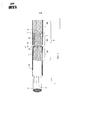
На фиг. 1 показана сигарета 1, содержащая табачный стержень 3 и многосекционный фильтр 5, которые могут удерживаться вместе посредством ободковой бумаги 15, что известно специалистам в этой области. Многосекционный фильтр 5 изготовлен из трех секций 5А, 5В, 5С фильтра, расположенных торец к торцу. В частности, фильтр 5 содержит среднюю секцию 5А фильтра с канавками, секцию 5В фильтра на мундштучном конце и секцию 5С фильтра, примыкающую к табачному стержню 3. Секция 5А фильтра с канавками расположена посередине между другими двумя секциями 5В, 5С фильтра (по отношению к главной оси цилиндра фильтра). Канавки 7 расположены на наружной стороне фильтра и продолжаются в основном в осевом направлении. Секция 5А фильтра предусмотрена с множеством канавок 7, которые распределены по периферии секции 5А фильтра. Канавки продолжаются вдоль по существу всей длины средней секции 5А фильтра, почти от табачного конца секции 5С до мундштучного конца секции 5В. Однако канавки не продолжаются в секцию 5С табачного конца фильтра или в секцию 5В мундштучного конца фильтра.In FIG. 1 shows a cigarette 1 comprising a
Канавки 7 отделены от секции 5С табачного конца фильтра непроницаемым барьером 9. Аналогично, канавки отделены от основной части 11 средней секции 5А фильтра непроницаемым слоем 6. Однако канавки открыты на конце, противоположном барьеру 9, чтобы воздух или другой газ/пар мог протекать вдоль канавки 7 для прохождения в секцию 5В мундштучного конца фильтра.The
В одном варианте осуществления непроницаемый слой 6 содержит непористую обертку (тампона) фильтра, которая окружает (по периферии) основную часть фильтрующего материала 11 в секции 5А фильтра. Этот фильтрующий материал 11 может содержать любой подходящий фильтрующий материал или структуру, например, полотно из ацетата целлюлозы, бумагу и т.д. Фильтрующий материал может быть предусмотрен с одной или более добавками, такими как активированный уголь и т.д. Непористая обертка 6 фильтра может быть гофрированной, чтобы она образовывала канавки 7 (с гофрами, проходящими параллельно цилиндрической оси фильтра). Фильтрующий материал 11 внутри непористой обертки фильтра в основном деформирован, чтобы он занимал все пространство внутри непористой обертки фильтра.In one embodiment, the
Отдельные секции фильтра скомбинированы с пористой наружной оберткой 13 фильтра. Эту наружную обертку фильтра затем располагают на гребнях или приподнятых гофрах внутренней обертки фильтра, с канавками, образованными между наружной оберткой фильтра и нижними (уменьшенного радиуса) участками внутренней обертки 6 фильтра.The individual sections of the filter are combined with a porous
При использовании курящий затягивается на секции 5В мундштучного конца фильтра. Это заставляет дым из горящего конца 2 табачного стержня проходить через стержень фильтра к курящему (как указано стрелками). Дым проходит через остальной (негорящий) табачный стержень 3 перед попаданием в фильтр 5. Дым сначала проходит через секцию 5С табачного конца фильтра, затем через основную часть 11 средней секции фильтра (поскольку дым не может пройти в канавки 7). Дым затем выходит из фильтра 5 через секцию 5 В мундштучного конца фильтра.In use, the smoker is drawn onto
Когда курящий затягивается на секции 5В мундштучного конца фильтра, при этом также втягивается воздух в канавки 7 через вентиляционные отверстия 17 и через обертку 13 фильтра, как указано стрелкой А. В основном сопротивление потоку через вентиляционные отверстия 17 и вдоль канавок 7 низкое, например, по сравнению с сопротивлением потоку через участок 11 основной части фильтра.When a smoker is drawn onto
После того, как воздух попадает в канавку 7, как указано стрелкой А, воздух ограничен в отношении перемещения вдоль канавки, как указано стрелкой В, поскольку стенки канавки, которые сформированы непористой внутренней оберткой 6 фильтра и ободковой бумагой 15, плюс барьер 9, в основном непроницаемые. Соответственно, поступающий воздух в конце концов выходит из канавок 7 в участок 5В мундштучного конца фильтра, где он смешивается с и разбавляет основной поток дыма из зоны 2 сгорания.After air enters the
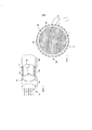
На фиг. 2 дополнительно схематично показан вариант осуществления по фиг. 1. Таким образом, на фиг. 2 показан вид в перспективе, иллюстрирующий периферийное распределение канавок 7 вокруг фильтра. Кроме того, на фиг. 2, в частности, показаны вентиляционные отверстия 17, расположенные над концами канавок 7, удаленных от мундштучного конца фильтра. В одном варианте осуществления эти вентиляционные отверстия 17 сформированы посредством лазерной перфорации, но может быть использован любой другой подходящий механизм. Вентиляционные отверстия могут быть расположены непосредственно над канавками (как схематично показано на фиг. 2) или в произвольной полосе или полосах, которые могут совпадать или не совпадать с канавками.In FIG. 2 further schematically shows an embodiment of FIG. 1. Thus, in FIG. 2 is a perspective view illustrating the peripheral distribution of
На фиг. 3 показано поперечное сечение через фильтр 5 в месте вентиляционных отверстий 17 на наружной стороне ободковой бумаги 15. По варианту осуществления, показанному на фиг. 3, вентиляционные отверстия в наружной части ободковой бумаги не все совпадают с канавками. Хотя существует зазор, показанный на фиг. 3 для ясности, между внутренней оберткой 6 фильтра и наружной оберткой 13 фильтра, и аналогично, зазор между наружной оберткой 13 фильтра и ободковой бумагой 15, очевидно, что на практике нет заметных зазоров, за исключением самих канавок.In FIG. 3 shows a cross-section through the
Очевидно, что число и распределение канавок 7, как показано на фиг. 2, 3 и 4, приведено только для примера. Другие варианты осуществления могут иметь другое число и(или) распределение канавок. Наличие канавок 7 в фильтре 5 позволяет разделить: (а) положение вентиляционных отверстий для поступающего воздуха, теперь на конце средней секции 5А фильтра в удалении от рта курящего; и (б) положение точки, где вентилирующий воздух соединяется с основным потоком дыма, теперь в месте соединения между средней секцией 5А фильтра и секцией 5В мундштучного конца фильтра. Возможность разделить эти два положения обеспечивает большую гибкость в выборе конструкции и управления фильтром 5.Obviously, the number and distribution of
Например, размещение вентиляционных отверстий на дальнем конце средней секции 5А фильтра, вдали от мундштучного конца, снижает риск того, что вентиляционные отверстия будут случайно закупорены ртом (например, губами) во время курения. В одном конкретном варианте осуществления вентиляционные отверстия расположены по меньшей мере на расстоянии примерно 11 мм от мундштучного конца фильтра, например, на расстоянии между примерно 12 мм и примерно 25 мм от мундштучного конца.For example, placing the ventilation openings at the far end of the
С другой стороны, наличие вентилирующего воздуха, входящего в поток дыма фильтра относительно близко ко рту, заставляет дым, проходящий через основную часть 11 средней секции, двигаться сравнительно медленно, что, в свою очередь, повышает эффективность фильтрации основной части 11 этой секции фильтра. В частности, поскольку составляющие дыма находятся дольше в непосредственной близости от фильтрующего материала 11 средней секции, велика вероятность того, что они будут адсорбированы этим материалом. Соответственно, фильтрующий материал может содержать адсорбирующий материал, такой как активированный уголь или другие подходящие адсорбенты.On the other hand, the presence of ventilating air entering the filter smoke stream relatively close to the mouth causes the smoke passing through the
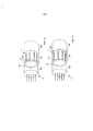
Два альтернативных варианта осуществления показаны на фиг. 4а и 46. В обоих этих вариантах осуществления для средней секции 5А фильтра (с канавками) предусмотрены дополнительные вентиляционные отверстия. В варианте осуществления по фиг. 4а, дополнительные вентиляционные отверстия 17А предусмотрены на дальнем конце средней секции 5А фильтра, удаленном от рта; т.е. на том же конце, что и вентиляционные отверстия 17 в канавки. Однако периферийное расположение этих отверстий 17А таково, что они не лежат над канавками. Таким образом, воздух проходит через вентиляционные отверстия 17А непосредственно в основную часть 11 фильтрующего материала для секции 5А фильтра. Соответственно, воздух, проходящий через вентиляционные отверстия 17А, не обходит фильтрующий материал 11 средней секции 5А фильтра, в противоположность воздуху, попадающему через вентиляционные отверстия 17, который направляется канавками непосредственно к секции 5В мундштучного конца фильтра.Two alternative embodiments are shown in FIG. 4a and 46. In both of these embodiments, additional air vents are provided for the
Следовательно, конфигурации по фиг. 4а и 4б предусматривают два эффективных положения для ввода вентилирующего воздуха, и, таким образом, позволяют повысить управление свойствами дыма и фильтра. Например, дополнительная вентиляция обеспечивает повышенное разбавление основного потока дыма, включая монооксид углерода и смолы. Дополнительная вентиляция также повышает скорость потока через основную часть 11 фильтра, которая снижает эффективность фильтрации для таких материалов, как смолы. В варианте осуществления по фиг. 4б дополнительные вентиляционные отверстия 17В предусмотрены на конце мундштука секции 5А с канавками. Поэтому воздух, проходящий через вентиляционные отверстия 17В, попадает в основной участок фильтра 5 в положении несколько выше по потоку дыма относительно воздуха, попадающего через вентиляционные отверстия 17 (и проходящего вдоль канавок 7). Общий результат конфигураций по фиг. 4а и 4б состоит в обеспечении повышенной вентиляции и, следовательно, повышенного разбавления дыма по сравнению с компоновкой по фиг. 2.Therefore, the configurations of FIG. 4a and 4b provide two effective positions for introducing ventilating air, and thus improve control of smoke and filter properties. For example, additional ventilation provides increased dilution of the mainstream smoke, including carbon monoxide and resins. Additional ventilation also increases the flow rate through the
Очевидно, что варианты осуществления по фиг. 4а и 4б могут быть скомбинированы в одном варианте осуществления, который обладает и дополнительными вентиляционными отверстиями 17А, и дополнительными вентиляционными отверстиями 17В. То есть, дополнительными вентиляционными отверстиями на обоих концах секции 5А фильтра с канавками. Также очевидно, что вентиляция, обеспечиваемая либо в канавки 17, либо в виде дополнительной вентиляции посредством перфорации 17А или 17В, может быть предусмотрена в широкой полосе или зоне поперек части или всей секции 5А фильтра.Obviously, the embodiments of FIG. 4a and 4b can be combined in one embodiment, which has both
Также очевидно, что число секций фильтра может быть отлично от 3 секций фильтра, показанных на фиг. 1, 2 и 4. Например, некоторые многосегментные фильтры могут содержать только 2 секции фильтра, в то время как другие многосегментные фильтры могут иметь четыре, пять или более секций фильтра. В основном, секция фильтра с канавками отделена от мундштучного конца фильтра по меньшей мере одной другой секцией фильтра (что помогает избежать закупоривания губой). Более того, в то время как на фиг. 1-4 показаны канавки, продолжающиеся по всей длине секции 5А фильтра с канавками, в других вариантах осуществления канавки могут продолжаться только частично вдоль секции фильтра с канавками. В таком случае канавки могут начинаться от табачного конца секции и(или) заканчиваться вдали от мундштучного конца этой секции. И наоборот, в некоторых случаях канавки могут продолжаться (полностью или частично) через несколько секций фильтра.It is also apparent that the number of filter sections may be different from the 3 filter sections shown in FIG. 1, 2 and 4. For example, some multi-segment filters may contain only 2 filter sections, while other multi-segment filters may have four, five or more filter sections. Basically, the grooved filter section is separated from the mouthpiece end of the filter by at least one other filter section (which helps to avoid lip clogging). Moreover, while in FIG. 1 to 4, grooves are shown extending along the entire length of the
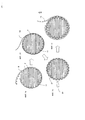
На фиг. 5 проиллюстрирован пример способа изготовления фильтра по одному варианту осуществления настоящей полезной модели. В этом примере лист непроницаемого материала 6 обертки фильтра гофрируют или тиснят для получения канавок 7. Материал с канавками обертывают вокруг цилиндра фильтрующего материала 11 (фиг. 5а). Канавки, показанные на фиг. 5, обладают профилем U-образной формы, но они могут обладать любым другим подходящим профилем, например, V-образным, или с прямыми углами вверху и внизу. В то время как канавки (фиг. 5а) показаны на внутренней поверхности материала 6 обертки фильтра, создавая, таким образом, каналы внутри основной части самого фильтрующего материала, очевидно, что каналы могут быть сформированы внешне относительно основной части фильтрующего материала 11. Кроме того, число и промежуток между канавками могут быть различны для разных вариантов осуществления. Например, могут быть непрерывные V-образные канавки (без промежутков), так что внутренняя обертка фильтра фактически обладает зигзагообразной конфигурацией.In FIG. 5, an example of a method for manufacturing a filter according to one embodiment of the present utility model is illustrated. In this example, a sheet of
При способе по фиг. 5 слой материала 13 наружной обертки фильтра теперь обернут вокруг наружной стороны стержня фильтра с канавками (фиг. 5б). Канавки 7 в материале внутренней обертки фильтра поэтому становятся закрытыми каналами между внутренней оберткой 6 фильтра и наружной оберткой 13 фильтра. Наружная обертка 13 фильтра может быть использована для связывания секции 11 фильтра с одной или более другими секциями фильтра, если это необходимо.In the method of FIG. 5, a layer of
Дополнительные вентиляционные отверстия 17 могут быть сформированы в наружной обертке 13 фильтра с помощью лазера 51 (фиг. 5в). Хотя наружная обертка 13 фильтра для ясности показана отделенной от внутренней обертки 6 фильтра, все-таки на деле они соприкасаются, как показано на фиг. 5б, за исключением мест, где расположены канавки. Вентиляционные отверстия 17 совпадают с канавками 7 и, следовательно, создают входные отверстия, чтобы воздух проходил в канавки. Могут быть предусмотрены дополнительные вентиляционные отверстия, которые не связаны с канавками (как показано выше на фиг. 4а и 4б). Такие вентиляционные отверстия могут быть сформированы, чтобы они проходили и через наружную, и через внутреннюю обертку фильтра, а также наружную ободковую бумагу.Additional ventilation holes 17 may be formed in the
Дополнительный слой листового материала 15, известный как ободковая бумага, впоследствии может быть наложен на вентилируемую обертку и секцию 5А фильтра с канавками (фиг. 5г). Ободковая бумага может быть использована для присоединения скомбинированных секций фильтра к табачному стержню, тем самым, скрепляя вместе компоненты готовой сигареты 1. Ободковая бумага может быть проницаемой (предварительно перфорированной) или непроницаемой. Непроницаемая ободковая бумага может вентилироваться посредством способов с использованием лазера на машине.An additional layer of
В другом варианте осуществления непрерывное формирование канавок в режиме онлайн может быть применено к стержню фильтра, например, путем обертывания непроницаемой внутренней обертки фильтра вокруг всей длины стержня, затем формированием канавок путем пропускания через формующее устройство определенной формы. Этот стержень фильтра затем может быть сегментирован для комбинирования с другими сегментами в многоэлементном фильтре. В альтернативном варианте к стержню фильтра может быть применено прерывное формирование канавок, например, путем выдавливания прерывных канавок в обернутом стержне, используя нагретые формующие устройства.In another embodiment, online continuous groove formation can be applied to the filter rod, for example, by wrapping an impermeable inner filter wrapper around the entire length of the rod, then forming grooves by passing a certain shape through the forming device. This filter rod can then be segmented for combination with other segments in a multi-element filter. Alternatively, discontinuous groove formation may be applied to the filter rod, for example, by extruding the discontinuous grooves in the wrapped rod using heated forming devices.
Когда используются способы формирования прерывных канавок, канавки закрыты для элемента на стороне табака секции с канавками посредством любого подходящего способа. Например, наружное кольцо (тороид) из пластмассы может быть вставлено между двумя элементами (как показано на фиг. 1). Другая возможность для этого уплотнения состоит в нанесении клея на конец канавки как можно дальше от рта.When methods for forming discontinuous grooves are used, the grooves are closed to the tobacco side member of the grooved section by any suitable method. For example, an outer ring (toroid) of plastic can be inserted between two elements (as shown in Fig. 1). Another possibility for this seal is to apply glue to the end of the groove as far as possible from the mouth.
Когда используются способы формирования прерывных канавок, сегменты фильтра комбинируют таким образом, чтобы канавки не достигали конца табачной стороны секции фильтра.When discontinuous groove forming methods are used, the filter segments are combined so that the grooves do not reach the end of the tobacco side of the filter section.
Канавки или каналы могут быть сформированы посредством любого из известных способов. Например в некоторых вариантах осуществления канавки могут быть сформированы непосредственно в фильтрующем материале, например, путем горячего формования фильтров из ацетата целлюлозы. В других вариантах осуществления, непроницаемой внутренней обертке фильтра может быть придана нужная форма или выполнено тиснение перед обертыванием вокруг цилиндра фильтрующего материала.Grooves or channels can be formed by any of the known methods. For example, in some embodiments, grooves can be formed directly in the filter material, for example, by hot forming filters from cellulose acetate. In other embodiments, the impermeable inner wrapper of the filter can be shaped or embossed before wrapping around the cylinder of filter material.
В некоторых вариантах осуществления применяется формирование непрерывных канавок посредством любых подходящих средств по всей длине стержня фильтра, который впоследствии сегментируют. В других вариантах осуществления формирование канавок применяется к секциям фильтра определенного размера.In some embodiments, continuous groove formation is applied by any suitable means along the entire length of the filter rod, which is subsequently segmented. In other embodiments, groove formation is applied to filter sections of a specific size.
В некоторых вариантах осуществления слой проницаемой обертки фильтра может быть использован для дополнительного покрытия оболочкой секции фильтра с канавками. Эта проницаемая обертка фильтра также может функционировать для комбинирования двух или более секций фильтра.In some embodiments, a permeable filter wrapper layer may be used to further cover the grooved filter section. This permeable filter wrap can also function to combine two or more filter sections.
Барьер 9 может быть сформирован посредством любого подходящего материала и(или) механизма. Например, одна из возможностей состоит в том, чтобы нанести пятно или полоску клея или другого непроницаемого материала в каждую канавку 7. Другая возможность состоит в обеспечении кольца из непроницаемого материала, например, пластмассы, которое проходит вокруг почти всей окружности 5, и отделяет (или закупоривает) канавки 7 от секции 5С на табачной стороне фильтра. Другая возможность состоит в обеспечении барьера 9 посредством сплавления фильтрующего материала 11 термоклеем.The
Дополнительный слой перфорированного или неперфорированного листового материала 15, известного как ободковая бумага, впоследствии наносят на скомбинированный фильтр и наложенную наружную обертку фильтра. Ободковая бумага может быть использована для присоединения скомбинированного фильтра к табачному стержню. Ободковая бумага может быть приклеена к фильтру и табачному стержню посредством любого подходящего средства, но может оставаться в большой мере неприклеенный участок поверх секции 5А с канавками.An additional layer of perforated or
В некоторых вариантах осуществления перфорация ободковой бумаги может быть предусмотрена посредством лазера или другого подходящего средства. Ободковая бумага может быть перфорирована перед или после присоединения к фильтру.In some embodiments, the perforation of the rim paper may be provided by a laser or other suitable means. The rim paper may be perforated before or after attaching to the filter.
Ободковая бумага приклеена к трем секциям фильтра с использованием способа приклеивания с проскоком зазора, чтобы в большой мере свободная от клея область была расположена между вентиляционными отверстиями и оберткой фильтра, наложенной на канавки. Очевидно, что использование адгезивов для соединения трех слоев (внутренняя обертка фильтра, наружная обертка фильтра и ободковый материал) вместе в положении, где образованы вентиляционные отверстия, приведет к закупориванию воздушных потоков и, следовательно, эту область по преимуществу оставляют непроклеенной.The rim paper is glued to the three sections of the filter using a gluing method with a gap gap, so that a large area free of glue is located between the ventilation holes and the filter wrapper overlaid on the grooves. Obviously, the use of adhesives to bond the three layers (inner filter wrap, outer filter wrap and rim material) together in the position where the ventilation holes are formed will clog the air flow and, therefore, this area is predominantly left uncoated.
Для специалистов в этой области будут очевидны различные модификации, которые могут быть внесены в варианты осуществления, описанные выше. Соответственно, объем настоящей полезной модели определяется прилагаемой формулой полезной модели и ее эквивалентами.Various modifications will be apparent to those skilled in the art that may be made to the embodiments described above. Accordingly, the scope of the present utility model is determined by the attached formula of the utility model and its equivalents.
Claims (18)

Applications Claiming Priority (2)
| Application Number | Priority Date | Filing Date | Title |
|---|---|---|---|
| GBGB0809865.9A GB0809865D0 (en) | 2008-05-30 | 2008-05-30 | Filter for a smoking article |
| GB0809865.9 | 2008-05-30 |
Related Parent Applications (1)
| Application Number | Title | Priority Date | Filing Date |
|---|---|---|---|
| RU2010153373 Division | 2010-12-27 |
Publications (1)
| Publication Number | Publication Date |
|---|---|
| RU148293U1 true RU148293U1 (en) | 2014-11-27 |
Family
ID=39637873
Family Applications (2)
| Application Number | Title | Priority Date | Filing Date |
|---|---|---|---|
| RU2014122922/12U RU148293U1 (en) | 2008-05-30 | 2009-05-27 | SMOKING PRODUCT WITH MULTI-SECTION FILTER |
| RU2010153373/12A RU2010153373A (en) | 2008-05-30 | 2009-05-27 | FILTER FOR SMOKING |
Family Applications After (1)
| Application Number | Title | Priority Date | Filing Date |
|---|---|---|---|
| RU2010153373/12A RU2010153373A (en) | 2008-05-30 | 2009-05-27 | FILTER FOR SMOKING |
Country Status (20)
| Country | Link |
|---|---|
| US (1) | US9066542B2 (en) |
| EP (1) | EP2328431B1 (en) |
| JP (1) | JP5883291B2 (en) |
| KR (1) | KR20110013528A (en) |
| CN (1) | CN102046034A (en) |
| AR (1) | AR074144A1 (en) |
| AU (1) | AU2009252940A1 (en) |
| BR (1) | BRPI0913104A2 (en) |
| CA (1) | CA2725121C (en) |
| CL (1) | CL2009001292A1 (en) |
| ES (1) | ES2425426T3 (en) |
| GB (1) | GB0809865D0 (en) |
| MX (1) | MX2010013126A (en) |
| MY (1) | MY169777A (en) |
| PL (1) | PL2328431T3 (en) |
| RU (2) | RU148293U1 (en) |
| TW (1) | TW201016149A (en) |
| UA (1) | UA99657C2 (en) |
| WO (1) | WO2009144496A1 (en) |
| ZA (1) | ZA201008495B (en) |
Cited By (2)
| Publication number | Priority date | Publication date | Assignee | Title |
|---|---|---|---|---|
| RU2803912C2 (en) * | 2018-09-07 | 2023-09-21 | Филип Моррис Продактс С.А. | Filter for electronic vapor device, electronic vapor device with filter and method for filter formation |
| US11950622B2 (en) | 2018-09-07 | 2024-04-09 | Altria Client Services Llc | Method of making capsule including filler material infused with consumable |
Families Citing this family (14)
| Publication number | Priority date | Publication date | Assignee | Title |
|---|---|---|---|---|
| GB0821803D0 (en) * | 2008-12-01 | 2009-01-07 | British American Tobacco Co | Smoking article filter |
| JP2011205917A (en) | 2010-03-29 | 2011-10-20 | British American Tobacco Japan Kk | Ventilation level-variable smoking article |
| GB201012732D0 (en) * | 2010-07-29 | 2010-09-15 | British American Tobacco Co | Smoking article filter |
| GB201016387D0 (en) * | 2010-09-29 | 2010-11-10 | Filtrona Int Ltd | Tobacco smoke filter |
| GB201110863D0 (en) | 2011-06-27 | 2011-08-10 | British American Tobacco Co | Smoking article filter and insertable filter unit thereof |
| GB201112466D0 (en) * | 2011-07-20 | 2011-08-31 | British American Tobacco Co | Smoking article |
| GB201114897D0 (en) * | 2011-08-30 | 2011-10-12 | British American Tobacco Co | Smoking article and method of manufacturing a smoking article |
| CN102511929A (en) * | 2011-11-10 | 2012-06-27 | 云南正邦生物技术有限公司 | Ventilative shape-fixed compound tip sticks and preparation method thereof |
| GB201207211D0 (en) * | 2012-04-25 | 2012-06-06 | British American Tobacco Co | Smoking articles |
| GB201213786D0 (en) | 2012-08-01 | 2012-09-12 | Filtrona Filter Prod Dev Co | Tobacco smoke filter |
| CN107752123A (en) * | 2017-10-19 | 2018-03-06 | 江苏中烟工业有限责任公司 | A kind of Three-section type heating containing sorbing material does not burn Cigarette |
| KR102330291B1 (en) * | 2018-07-04 | 2021-11-24 | 주식회사 케이티앤지 | Cigarrets |
| CN109619671A (en) * | 2018-11-22 | 2019-04-16 | 湖北中烟工业有限责任公司 | A kind of cigarette with high-air-permeability |
| JP2022552767A (en) * | 2019-10-28 | 2022-12-20 | ジェイティー インターナショナル エス.エイ. | Filter components for aerosol-generating articles |
Family Cites Families (34)
| Publication number | Priority date | Publication date | Assignee | Title |
|---|---|---|---|---|
| GB1308661A (en) | 1970-02-21 | 1973-02-21 | Cigarette Components Ltd | Device for treating tobacco smoke |
| US3768489A (en) * | 1970-10-05 | 1973-10-30 | Eastman Kodak Co | Tobacco smoke filter |
| US3752165A (en) * | 1971-12-20 | 1973-08-14 | G Harllee | Smoke filter plug and process and cigarette made therefrom |
| GB1508084A (en) * | 1976-03-17 | 1978-04-19 | British American Tobacco Co | Tobacco-smoke filters |
| GB1585862A (en) | 1976-11-19 | 1981-03-11 | British American Tobacco Co | Tobacco-smoke filters |
| US4350173A (en) * | 1978-11-30 | 1982-09-21 | Siren Matti J | Filter material |
| US4256122A (en) * | 1979-04-11 | 1981-03-17 | Brown & Williamson Tobacco Corporation | Cigarette filter |
| TR21005A (en) | 1980-11-21 | 1983-05-01 | Brown & Williamson Tobacco | A SMOKING FILTER THAT NEEDS A SMOKE NON-DELIVERABLE WRAP A REMOVER OF MESAMATH FILTER BAR. |
| US4343319A (en) | 1980-11-28 | 1982-08-10 | Brown & Williamson Tobacco Corporation | Cigarette filter |
| US4362172A (en) | 1980-12-01 | 1982-12-07 | Brown & Williamson Tobacco Corporation | Cigarette filter |
| US4342322A (en) | 1980-12-22 | 1982-08-03 | Brown & Williamson Tobacco Corporation | Cigarette filter |
| GB2090117B (en) | 1980-12-22 | 1985-08-21 | Imp Group Ltd | Ventilated cigarette tip |
| BE891549A (en) * | 1980-12-22 | 1982-04-16 | Imp Group Ltd | TERMINATION ASSEMBLY FOR AN EXTENDED SMOKING ARTICLE |
| US4582071A (en) * | 1980-12-22 | 1986-04-15 | Imperial Group Limited | Tipping assembly for an elongate smoking article |
| US4637409A (en) * | 1981-05-07 | 1987-01-20 | American Filtrona Corporation | Tobacco smoke filter and method and apparatus for making same |
| US4552158A (en) * | 1981-12-23 | 1985-11-12 | American Filtrona Corporation | Free air dilution smoke filter and method and apparatus for fabricating same |
| US4406294A (en) | 1982-02-16 | 1983-09-27 | Brown & Williamson Tobacco Corporation | Cigarette filter |
| NO157125C (en) | 1982-04-08 | 1988-06-01 | Filtrona Ltd | CIGARETTE FILTER ELEMENT, ALTERNATIVE WITH AN ENVIRONMENTAL, VENTILATING NOZZLE MATERIAL. |
| US4527573A (en) * | 1982-11-05 | 1985-07-09 | Philip Morris Incorporated | Filter cigarette |
| US4527572A (en) * | 1983-02-07 | 1985-07-09 | Brown & Williamson Tobacco Corporation | Tobacco smoke filters |
| US4557281A (en) * | 1983-12-05 | 1985-12-10 | Brown & Williamson Tobacco Corporation | Filtered cigarette |
| US4542754A (en) * | 1983-12-05 | 1985-09-24 | Brown & Williamson Tobacco Corporation | Filtered cigarette |
| US4580584A (en) * | 1984-02-21 | 1986-04-08 | Brown & Williamson Tobacco Corporation | Cigarette filter |
| EP0167863B1 (en) * | 1984-06-20 | 1988-01-07 | H.F. & Ph.F. Reemtsma GmbH & Co | Cigarette filter with variable ventilation |
| JPH0479875A (en) * | 1990-07-20 | 1992-03-13 | Japan Tobacco Inc | Tobacco having filter |
| US5178166A (en) | 1990-09-20 | 1993-01-12 | Philip Morris Incorporated | Filter cigarette |
| PT664964E (en) | 1994-01-27 | 2003-10-31 | British American Tobacco Co | SMOKE RELATED APPROPERTIES |
| JPH09316420A (en) * | 1996-05-27 | 1997-12-09 | Daicel Chem Ind Ltd | Water-soluble hot melt adhesive, cigarette filter using the same and their production |
| JP3181248B2 (en) * | 1997-10-06 | 2001-07-03 | 日本たばこ産業株式会社 | Cigarette with filter and filter for cigarette |
| ATE341234T1 (en) | 2001-12-18 | 2006-10-15 | Bat Cigarettenfab Gmbh | FILTER FOR A SMOKABLE ARTICLE |
| AU2006202993B2 (en) * | 2001-12-18 | 2007-09-20 | British American Tobacco (Investments) Limited | Ventilated smoking article |
| US7237558B2 (en) * | 2003-09-30 | 2007-07-03 | R. J. Reynolds Tobacco Company | Filtered cigarette incorporating an adsorbent material |
| EP1797780A1 (en) | 2005-12-15 | 2007-06-20 | Gallaher Limited | Smoking article |
| US8424539B2 (en) * | 2006-08-08 | 2013-04-23 | Philip Morris Usa Inc. | Smoking article with single piece restrictor and chamber |
-
2008
- 2008-05-30 GB GBGB0809865.9A patent/GB0809865D0/en not_active Ceased
-
2009
- 2009-05-26 CL CL2009001292A patent/CL2009001292A1/en unknown
- 2009-05-27 MX MX2010013126A patent/MX2010013126A/en active IP Right Grant
- 2009-05-27 MY MYPI2010005475A patent/MY169777A/en unknown
- 2009-05-27 PL PL09754141T patent/PL2328431T3/en unknown
- 2009-05-27 CA CA2725121A patent/CA2725121C/en not_active Expired - Fee Related
- 2009-05-27 WO PCT/GB2009/050573 patent/WO2009144496A1/en active Application Filing
- 2009-05-27 RU RU2014122922/12U patent/RU148293U1/en active
- 2009-05-27 ES ES09754141T patent/ES2425426T3/en active Active
- 2009-05-27 KR KR1020107029300A patent/KR20110013528A/en not_active Application Discontinuation
- 2009-05-27 AU AU2009252940A patent/AU2009252940A1/en not_active Abandoned
- 2009-05-27 JP JP2011511095A patent/JP5883291B2/en not_active Expired - Fee Related
- 2009-05-27 TW TW098117576A patent/TW201016149A/en unknown
- 2009-05-27 BR BRPI0913104A patent/BRPI0913104A2/en not_active IP Right Cessation
- 2009-05-27 EP EP09754141.1A patent/EP2328431B1/en not_active Not-in-force
- 2009-05-27 RU RU2010153373/12A patent/RU2010153373A/en unknown
- 2009-05-27 UA UAA201015597A patent/UA99657C2/en unknown
- 2009-05-27 CN CN2009801201274A patent/CN102046034A/en active Pending
- 2009-05-27 US US12/995,232 patent/US9066542B2/en not_active Expired - Fee Related
- 2009-05-28 AR ARP090101918A patent/AR074144A1/en not_active Application Discontinuation
-
2010
- 2010-11-25 ZA ZA2010/08495A patent/ZA201008495B/en unknown
Cited By (2)
| Publication number | Priority date | Publication date | Assignee | Title |
|---|---|---|---|---|
| RU2803912C2 (en) * | 2018-09-07 | 2023-09-21 | Филип Моррис Продактс С.А. | Filter for electronic vapor device, electronic vapor device with filter and method for filter formation |
| US11950622B2 (en) | 2018-09-07 | 2024-04-09 | Altria Client Services Llc | Method of making capsule including filler material infused with consumable |
Also Published As
| Publication number | Publication date |
|---|---|
| ES2425426T3 (en) | 2013-10-15 |
| TW201016149A (en) | 2010-05-01 |
| AU2009252940A1 (en) | 2009-12-03 |
| WO2009144496A1 (en) | 2009-12-03 |
| PL2328431T3 (en) | 2013-10-31 |
| US9066542B2 (en) | 2015-06-30 |
| RU2010153373A (en) | 2012-07-10 |
| BRPI0913104A2 (en) | 2016-01-05 |
| KR20110013528A (en) | 2011-02-09 |
| CA2725121C (en) | 2014-01-07 |
| UA99657C2 (en) | 2012-09-10 |
| MY169777A (en) | 2019-05-15 |
| AR074144A1 (en) | 2010-12-29 |
| GB0809865D0 (en) | 2008-07-09 |
| JP5883291B2 (en) | 2016-03-09 |
| EP2328431A1 (en) | 2011-06-08 |
| MX2010013126A (en) | 2011-01-14 |
| US20110155155A1 (en) | 2011-06-30 |
| CA2725121A1 (en) | 2009-12-03 |
| EP2328431B1 (en) | 2013-05-22 |
| JP2011521634A (en) | 2011-07-28 |
| CL2009001292A1 (en) | 2010-10-01 |
| CN102046034A (en) | 2011-05-04 |
| ZA201008495B (en) | 2014-05-28 |
Similar Documents
| Publication | Publication Date | Title |
|---|---|---|
| RU148293U1 (en) | SMOKING PRODUCT WITH MULTI-SECTION FILTER | |
| JP6042829B2 (en) | Cigarette smoke filter | |
| RU2528347C2 (en) | Ventilating shell for smoking product | |
| JP5857127B2 (en) | Smoking goods | |
| US4582071A (en) | Tipping assembly for an elongate smoking article | |
| CA2742396C (en) | Smoking article filter | |
| JP2009531052A (en) | Smoking articles with limiters | |
| KR20010049812A (en) | Filter for a cigarette and a filter-tipped cigarette | |
| JPS5832955B2 (en) | cigarette filter | |
| AU2008337827A1 (en) | Recessed ventilation for smoking articles | |
| RU2413438C2 (en) | Filter or filtering element for tobacco smoke, cigarette with such filter or filtering element and method to manufacture such filter or filtering element | |
| GB2119221A (en) | Cigarette filter | |
| TW200924654A (en) | Filter and method for making a filter for a cigarette | |
| WO2010076325A1 (en) | Ventilated smoking article | |
| RU2573966C2 (en) | Ventilated smoking product | |
| GB2090117A (en) | Ventilated cigarette tip | |
| CN206324222U (en) | Tri compound cavity rotates filter stick and the cigarette containing the filter stick | |
| PH12014502404B1 (en) | Smoking article with concentric filter | |
| IE60900B1 (en) | Cigarette filter | |
| GB2095532A (en) | Ventilated and corrugated smoke filter | |
| RU2295267C1 (en) | Cigarette |