RU130717U1 - AC THRESHOLD DEVICE - Google Patents
AC THRESHOLD DEVICE Download PDFInfo
- Publication number
- RU130717U1 RU130717U1 RU2013114270/28U RU2013114270U RU130717U1 RU 130717 U1 RU130717 U1 RU 130717U1 RU 2013114270/28 U RU2013114270/28 U RU 2013114270/28U RU 2013114270 U RU2013114270 U RU 2013114270U RU 130717 U1 RU130717 U1 RU 130717U1
- Authority
- RU
- Russia
- Prior art keywords
- threshold
- semiconductor
- comparator
- threshold element
- rectifier unit
- Prior art date
Links
Images


Landscapes
- Measurement Of Current Or Voltage (AREA)
Abstract
1. Пороговое устройство контроля переменного тока, содержащее датчик тока, задатчик опорного сигнала, компаратор, выходные клеммы для подключения внешнего устройства, работающего по сигналу от компаратора, отличающееся тем, что датчиком тока служит трансформатор переменного тока, вторичная обмотка которого зашунтирована резистором, являющимся задатчиком опорного напряжения, в качестве компаратора использован полупроводниковый пороговый элемент, а между трансформатором переменного тока и полупроводниковым пороговым элементом включен выпрямительный блок со сглаживающим конденсатором на своем выходе.2. Пороговое устройство по п.1, отличающееся тем, что выпрямительный блок представляет собой полупроводниковый мост, а в качестве полупроводникового порогового элемента использовано твердотельное реле.3. Пороговое устройство по п.1, отличающееся тем, что выпрямительный блок выполнен в виде умножителя напряжения, а полупроводниковый пороговый элемент выполнен в виде полевого транзистора с изолированным затвором.1. A threshold AC control device containing a current sensor, a reference signal setter, a comparator, output terminals for connecting an external device operating on a signal from the comparator, characterized in that the current sensor is an AC transformer, the secondary winding of which is shunted by a resistor, which is a setter reference voltage, a semiconductor threshold element is used as a comparator, and an inclusive threshold between the AC transformer and the semiconductor threshold element n rectifier unit with smoothing capacitor on its vyhode.2. The threshold device according to claim 1, characterized in that the rectifier unit is a semiconductor bridge, and a solid-state relay is used as a semiconductor threshold element. The threshold device according to claim 1, characterized in that the rectifier unit is made in the form of a voltage multiplier, and the semiconductor threshold element is made in the form of a field effect transistor with an insulated gate.
Description
Область техникиTechnical field
Полезная модель относится к приборам, созданным на базе пороговых реле для контролирования в электрической цепи наличия переменного тока.The utility model relates to devices created on the basis of threshold relays for monitoring the presence of alternating current in an electric circuit.
Уровень техникиState of the art
Известны разновидности датчиков тока, используемые в качестве пороговых элементов, выключающие силовые электрические цепи при достижении током определенного заранее заданного значения.There are known varieties of current sensors used as threshold elements that turn off power electric circuits when the current reaches a certain predetermined value.
Выпускаются токовые реле прямого действия, мгновенные типа РТМ и с ограниченной зависимой характеристикой. Они отличаются простотой, небольшой стоимостью и представляют собой электромагнитное реле с втягивающимся якорем. К недостаткам таких реле относятся большие выдержки времени, низкая точность установки порога срабатывания, значительные габариты и энергопотребление. Н.В. Чернобровов, В.А Семенов. «Релейная защита энергетических систем», Энергоатомиздат. 1988. стр.223-224.Direct current, instantaneous type RTM relays and with a limited dependent characteristic are available. They are simple, low cost and are an electromagnetic relay with a retractable armature. The disadvantages of such relays include long time delays, low accuracy of setting the threshold, significant dimensions and power consumption. N.V. Chernobrovov, V.A. Semenov. “Relay protection of energy systems”, Energoatomizdat. 1988. p. 233-224.
В качестве токовой защиты используются также автоматические выключатели с тепловыми элементами. В.И.Гуревич. «Электрические реле». М. Солон-пресс. ДМК-пресс. 2011. стр.244-249. В них как правило биметаллический тепловой элемент дополнен встроенным электромагнитом с катушкой. Этот вид реле имеет те же недостатки, что и электромагнитные реле, и особенно большую инерционность. Применение всех упомянутых решений затруднено также вследствие больших энергозатрат на переключение реле.As current protection, circuit breakers with thermal elements are also used. V.I. Gurevich. "Electrical relays." M. Solon-press. DMK-press. 2011. p. 244-249. In them, as a rule, a bimetallic thermal element is supplemented by a built-in electromagnet with a coil. This type of relay has the same drawbacks as electromagnetic relays, and especially the large inertia. The application of all these solutions is also difficult due to the large energy consumption for switching the relay.
Наиболее малогабаритными, высоконадежными, точными и дешевыми являются пороговые реле с использованием полупроводниковых приборов, в частности, включающих в себя, в качестве входного чувствительного устройства, датчиков Холла. Это, например, датчики тока серии CSDA фирмы HONEYWELL. Структура этих датчиков включает в себя магнитопровод и датчик Холла с логическим выходом. Логическое состояние на выходе датчика изменяется при превышении одного из установленных пороговых значений. Порог срабатывания определяется числом витков измеряемого проводника вокруг датчика.The most small-sized, highly reliable, accurate and cheap are threshold relays using semiconductor devices, in particular, including Hall sensors as an input sensitive device. These are, for example, HONEYWELL CSDA series current sensors. The structure of these sensors includes a magnetic circuit and a Hall sensor with a logic output. The logical state at the sensor output changes when one of the set threshold values is exceeded. The response threshold is determined by the number of turns of the measured conductor around the sensor.
Наиболее подробная схема такого порогового токового реле на датчике Холла приведена в опубликованной заявке на патент США №20110228433. Эта схема принимается за прототип. Согласно принципиальной схеме аналога пороговое токовое реле состоит из датчика Холла, фильтра и компаратора, соединенных последовательно, и блока опорного напряжения, подающего сигнал на компаратор, где производится его сравнение с отфильтрованным сигналом от датчика Холла. При совпадении этих сигналов компаратор вырабатывает сигнал управления, передаваемый драйверу устройства размыкания цепи. Для электропитания датчика Холла в составе схемы реле имеются блоки преобразования напряжения.The most detailed circuit of such a threshold current relay on a Hall sensor is given in published patent application US No. 1021028433. This scheme is taken as a prototype. According to the analog circuit diagram, the threshold current relay consists of a Hall sensor, a filter and a comparator connected in series, and a reference voltage unit supplying a signal to the comparator, where it is compared with the filtered signal from the Hall sensor. When these signals coincide, the comparator generates a control signal transmitted to the circuit breaker device driver. For power supply of the Hall sensor, the relay circuit contains voltage conversion units.
Недостатком прототипа является наличие сложного дорогого датчика Холла и необходимость дополнительного источника электропитания для его электроснабжения.The disadvantage of the prototype is the presence of a complex expensive Hall sensor and the need for an additional power source for its power supply.
Целью создания полезной модели является создание более простого устройства, не требующего при измерениях дополнительного источника электропитания, обеспечивающего контроль токов в широком диапазоне значений.The purpose of creating a utility model is to create a simpler device that does not require an additional power source during measurements, providing current control over a wide range of values.
Раскрытие полезной моделиUtility Model Disclosure
Пороговое устройство контроля переменного тока включает в себя следующие компоненты:The threshold AC monitoring device includes the following components:
- трансформатор переменного тока, исполняющий роль датчика,- AC transformer acting as a sensor,
- резистор, шунтирующий выходную обмотку, сопротивление которого определяет установленный порог срабатывания реле;- a resistor shunting the output winding, the resistance of which determines the set threshold for the relay;
- выпрямительный блок, преобразующий переменное напряжение в постоянное;- a rectifier unit that converts an alternating voltage to a constant;
- полупроводниковый пороговый элемент (по сути - компаратор), сравнивающий входное напряжение с опорным, и выдающий на выходе импульсный сигнал при отклонении значения входного сигнала от опорного.- a semiconductor threshold element (essentially a comparator) that compares the input voltage with the reference voltage and generates a pulse signal at the output when the value of the input signal deviates from the reference.
В качестве полупроводникового порогового элемента может использоваться твердотельное реле или полевой транзистор с изолированным затвором. В последнем случае выпрямитель выполнен по схеме умножителя напряжения для усиления сигнала, полученного от датчика и, соответственно, увеличения чувствительности всего устройства.A solid state relay or an insulated gate field effect transistor can be used as a semiconductor threshold element. In the latter case, the rectifier is made according to the scheme of the voltage multiplier to amplify the signal received from the sensor and, accordingly, increase the sensitivity of the entire device.
Ток, протекающий по вторичной обмотке трансформатора тока, пропорционален току, протекающему в его первичной обмотке. Первичной обмоткой является проводник с контролируемым током.The current flowing through the secondary winding of the current transformer is proportional to the current flowing in its primary winding. The primary winding is a conductor with a controlled current.
Величина сопротивления резистора, подключенного параллельно вторичной обмотке, определяет величину опорного напряжения, которое поступает на вход порогового элемента через выпрямительный блок. При превышении уровня входного сигнала выше заданного, проводимость порогового элемента скачкообразно меняется. Это свойство позволяет сформировать на выходе порогового элемента импульс, который может подаваться на вход любого контролирующего устройства, подключаемого к выходным клеммам порогового элемента управляющий индикаторным или иным устройством.The resistance value of the resistor connected in parallel with the secondary winding determines the value of the reference voltage, which is supplied to the input of the threshold element through the rectifier block. If the input signal exceeds a predetermined level, the conductivity of the threshold element changes stepwise. This property allows you to generate an impulse at the output of the threshold element, which can be fed to the input of any control device connected to the output terminals of the threshold element that controls the indicator or other device.
Чувствительность предлагаемого устройства может быть достаточно высокой и определяется схемным решением выпрямительного блока.The sensitivity of the proposed device can be quite high and is determined by the circuit design of the rectifier unit.
При индикации малых токов (0,1-3,0 A) выпрямительный блок может быть реализован в виде классического умножителя напряжения, включающего в себя также выпрямитель и сглаживающий конденсатор.When indicating low currents (0.1-3.0 A), the rectifier unit can be implemented as a classic voltage multiplier, which also includes a rectifier and a smoothing capacitor.
Для контроля более сильных токов(от 3 A и выше) выпрямительный блок может быть реализован на простом диодном выпрямительном мосте и конденсаторе на его выходе для сглаживания пульсаций.To control stronger currents (from 3 A and above), the rectifier unit can be implemented on a simple diode rectifier bridge and a capacitor at its output to smooth out ripples.
Сущность полезной модели заключается в отсутствии внешнего источника питающего напряжения. Вместо него питание схемы организовано от напряжения, наведенного током контролируемого проводника в обмотке трансформатора тока.The essence of the utility model is the absence of an external source of supply voltage. Instead, the power supply to the circuit is organized from the voltage induced by the current of the controlled conductor in the current transformer winding.
Таким образом, предлагаемая полезная модель не нуждается при измерениях в дополнительном источнике электропитания, обеспечивая при этом высокую чувствительность при контроле даже очень небольших токов (от 0,1 A).Thus, the proposed utility model does not need an additional power supply for measurements, while ensuring high sensitivity when monitoring even very small currents (from 0.1 A).
Графические иллюстрацииGraphic illustration
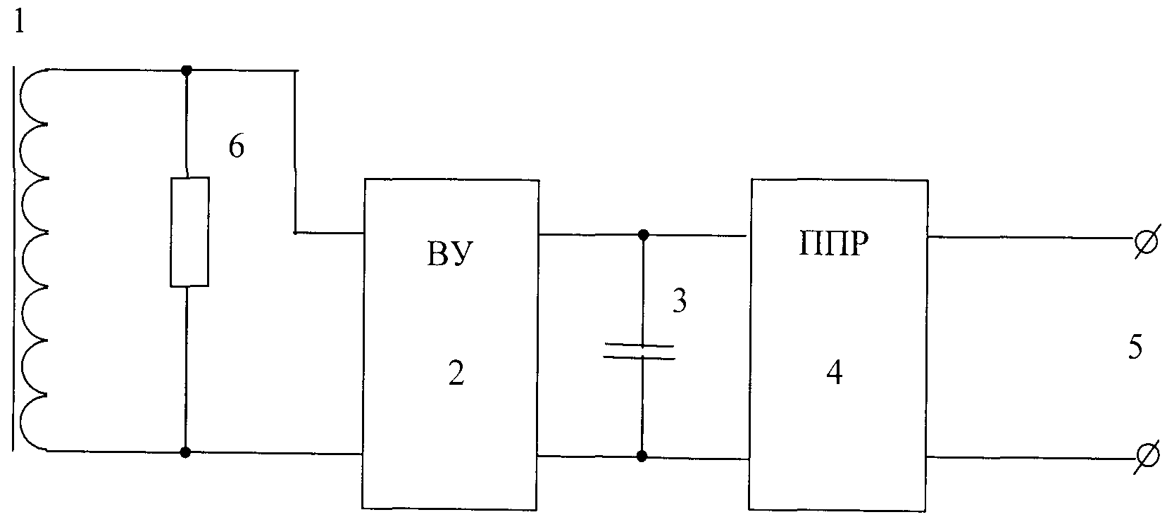
Фиг.1 Структурная схема порогового устройства для контроля переменного тока.Figure 1 Structural diagram of a threshold device for monitoring AC.
Фиг.2 Пример выполнения порогового устройство для контроля переменного тока с использованием твердотельного реле.Figure 2 An example of a threshold device for monitoring AC using a solid state relay.
Фиг.3 Пример выполнения порогового устройства для контроля переменного тока с использованием полевого транзистора.Figure 3 An example of a threshold device for controlling AC using a field effect transistor.
Осуществление полезной моделиUtility Model Implementation
Структурная схема порогового устройства для контроля переменного тока (фиг.1) содержит: трансформатор тока 1, выпрямительное устройство (ВУ) 2, на выходе которого подсоединен сглаживающий конденсатор 3, полупроводниковый пороговый элемент 4, на выходе которого имеются клеммы 5 для подключения внешнего контролирующего прибора (Фиг.1).The structural diagram of a threshold device for monitoring AC current (Fig. 1) contains: a
Трансформатор тока 1, исполняющий роль датчика тока, выполнен на тороидальном сердечнике из аморфного железа. Проводник с контролируемым током, размещаемый внутри сердечника, является первичной обмоткой трансформатора. Вторичная обмотка трансформатора тока зашунтирована резистором 6, служащим задатчиком уровня опорного сигнала. Изменяя величину сопротивления этого резистора, можно изменять порог срабатывания полупроводникового порогового элемента 4.
В примере выполнения порогового устройства (Фиг.2), пригодного для контроля токов величиной от 3 A, в качестве полупроводникового порогового элемента использовано твердотельное реле 7 (типа КР293КП9А с оптической развязкой входа и выхода) с диодной защитой (схема защиты по току 8) по входу от предельных токов.In the example of the implementation of the threshold device (Figure 2), suitable for monitoring currents with a magnitude of 3 A or more, a solid-state relay 7 (type КР293КП9А with optical isolation of the input and output) with diode protection (current protection circuit 8) is used as a semiconductor threshold element input from limiting currents.
В примере выполнения порогового устройства (Фиг.3), пригодного для контроля токов величиной от 0,1 A (Фиг.3), в качестве полупроводникового порогового элемента использован полевой транзистор 9 с изолированным затвором и индуцированным каналом, включенный по схеме с общим истоком (например IRLL014N). Выход транзистора защищен диодом 10 для защиты от бросков тока (в IRLL014N диод встроенный). Выпрямительный блок в этом случае выполнен по схеме умножителя напряжения 11 на восьми диодах Шоттки.In an example embodiment of a threshold device (FIG. 3) suitable for monitoring currents with a magnitude of 0.1 A or more (FIG. 3), a field-
Конструктивно пороговое устройство для контроля переменного тока может быть реализовано на печатной плате, а трансформатор тока выполнен в виде кольцевого магнитопровода с обмоткой, внутри которого размещается контролируемая токовая шина.Structurally, a threshold device for controlling alternating current can be implemented on a printed circuit board, and the current transformer is made in the form of an annular magnetic circuit with a winding inside which a controlled current bus is placed.
Пороговое устройство для контроля переменного тока работает следующим образом. Контролируемый переменный ток протекает по шине, проходящей через сердечник трансформатора тока 1, генерирует переменное напряжение во вторичной обмотке трансформатора на шунтирующем резисторе 6. Это переменное напряжение преобразуется в постоянное - на выпрямительном блоке 2 и затем поступает на полупроводниковый пороговый элемент 3. Сопротивление резистора 6 определяет величину опорного напряжения для полупроводникового порогового элемента (т.е. определяет его порог срабатывания). При изменении контролируемого тока (например, при обрыве цепи) изменяется уровень входного сигнала, поступающего через выпрямительный блок 2 на вход полупроводникового порогового элемента 3 (с какого-то значения до 0), что приводит к резкому изменению проводимости порогового элемента и формированию импульсного выходного сигнала на выходных клеммах 5 (поступающего на внешнее устройство индикации или контроля).A threshold device for monitoring AC operates as follows. A controlled alternating current flows through the bus passing through the core of
В качестве внешнего устройства может быть любой индикатор, например, лампочка, или более сложное устройство - регистрирующий компьютерный блок.An external device can be any indicator, for example, a light bulb, or a more complex device - a recording computer unit.
Схема на диодах 8 (фиг.2) обеспечивает защиту от перегрузки по току входа полупроводникового порогового элемента.The circuit on the diodes 8 (figure 2) provides protection against overcurrent of the input of the semiconductor threshold element.
При контролировании малых токов от 01, до 3 A (фиг.3) сигнал выпрямляется и усиливается умножителем напряжения 11, коэффициент усиления которого определяет чувствительность устройства. Усиленный сигнал поступает на затвор полевого транзистора 9 с изолированным затвором. При достижении напряжения на затворе уровня срабатывания, происходит скачкообразное изменение сопротивления канала сток-исток полевого транзистора. Диод 10 шунтирует нежелательные броски обратного тока при работе устройства с индуктивной нагрузкой. Это решение путем подбора параметров умножителя напряжения 11 позволяет улавливать даже очень малые изменения контролируемого тока.When controlling small currents from 01 to 3 A (Fig. 3), the signal is rectified and amplified by a
В настоящее время изготовлены и прошли успешные испытания опытные образцы пороговых устройств контроля переменного тока на основе предлагаемой полезной модели.Currently, prototypes of threshold AC control devices based on the proposed utility model have been manufactured and successfully tested.
Claims (3)
Priority Applications (1)
| Application Number | Priority Date | Filing Date | Title |
|---|---|---|---|
| RU2013114270/28U RU130717U1 (en) | 2013-03-29 | 2013-03-29 | AC THRESHOLD DEVICE |
Applications Claiming Priority (1)
| Application Number | Priority Date | Filing Date | Title |
|---|---|---|---|
| RU2013114270/28U RU130717U1 (en) | 2013-03-29 | 2013-03-29 | AC THRESHOLD DEVICE |
Publications (1)
| Publication Number | Publication Date |
|---|---|
| RU130717U1 true RU130717U1 (en) | 2013-07-27 |
Family
ID=49156038
Family Applications (1)
| Application Number | Title | Priority Date | Filing Date |
|---|---|---|---|
| RU2013114270/28U RU130717U1 (en) | 2013-03-29 | 2013-03-29 | AC THRESHOLD DEVICE |
Country Status (1)
| Country | Link |
|---|---|
| RU (1) | RU130717U1 (en) |
-
2013
- 2013-03-29 RU RU2013114270/28U patent/RU130717U1/en not_active IP Right Cessation
Similar Documents
| Publication | Publication Date | Title |
|---|---|---|
| EP3484035B1 (en) | Hysteresis power supply circuit | |
| US8896334B2 (en) | System for measuring soft starter current and method of making same | |
| HRP20170389T1 (en) | Devices and methods for overvoltage protection | |
| US7737645B2 (en) | Electronic tripping unit for a motor-circuit breaker of an electric motor | |
| US20150333509A1 (en) | Protective Circuit for a Current Transformer and Current Transformer with a Protection Circuit | |
| CN104158141B (en) | Self-power circuit for protecting relay | |
| US9780551B2 (en) | Differential protection device for a switchgear apparatus, and electric switchgear apparatus comprising one such device | |
| RU2012135678A (en) | MAXIMUM CURRENT DISCONNECTOR FOR PROTECTIVE AUTOMATION | |
| KR20120067797A (en) | Current detection apparatus using sensor | |
| RU130717U1 (en) | AC THRESHOLD DEVICE | |
| KR101473109B1 (en) | Current transformer protector | |
| KR101691399B1 (en) | Limiter device capable of contact failure detection having delay circuit | |
| CN102354943A (en) | Work method of electronic release | |
| RU2016110766A (en) | CURRENT LOOP INPUT PROTECTION | |
| US9600012B2 (en) | Internal power supply of a device | |
| US20200186029A1 (en) | Arrangement and method for current measurement | |
| US8817442B2 (en) | Switch comprising a testable current transformer, and method for testing a current transformer of a switch | |
| CN211402517U (en) | Current detection circuit applied to elevator device | |
| CN104620455A (en) | A power supply and measuring device for an intelligent electronic device | |
| CN218449462U (en) | Strong electricity overvoltage automated inspection protection circuit | |
| RU104526U1 (en) | AC RAIL CIRCUIT | |
| CN211790736U (en) | Leakage protector circuit of independent power supply tripping | |
| RU187861U1 (en) | Zero Current Transition Detector | |
| RU124453U1 (en) | PROTECTIVE CIRCUIT BREAKER (OPTIONS) | |
| JP2022086494A (en) | Surge detection device |
Legal Events
| Date | Code | Title | Description |
|---|---|---|---|
| MM9K | Utility model has become invalid (non-payment of fees) |
Effective date: 20210330 |