RU123961U1 - TRANSPORT SENSOR RING SUSPENSION UNIT TUBES - Google Patents
TRANSPORT SENSOR RING SUSPENSION UNIT TUBES Download PDFInfo
- Publication number
- RU123961U1 RU123961U1 RU2012121301/28U RU2012121301U RU123961U1 RU 123961 U1 RU123961 U1 RU 123961U1 RU 2012121301/28 U RU2012121301/28 U RU 2012121301/28U RU 2012121301 U RU2012121301 U RU 2012121301U RU 123961 U1 RU123961 U1 RU 123961U1
- Authority
- RU
- Russia
- Prior art keywords
- ring
- sensors
- flaw detector
- transport module
- movable
- Prior art date
Links
Images


Landscapes
- Investigating Or Analyzing Materials By The Use Of Ultrasonic Waves (AREA)
- Investigating Or Analyzing Materials By The Use Of Magnetic Means (AREA)
Abstract
1. Узел подвески кольца датчиков транспортного модуля дефектоскопа внутритрубного, включающий в себя подвижное в плоскости, перпендикулярной оси симметрии транспортного модуля, кольцо датчиков, на котором осесимметрично размещены шарнирно закрепленные рычаги с измерительными датчиками и пружинами (например, пластинчатыми, обеспечивающими прижатие измерительных датчиков к стенке трубопровода), отличающийся тем, что представляет собой систему трех подвижных фланцев, замкнутой направляющей овальной формы, полиуретанового кольца и неподвижного фланца с выборками, жестко закрепленного на корпусе транспортного модуля дефектоскопа, причем первый из трех подвижных фланцев, через выборки неподвижного фланца соединен со вторым из подвижных фланцев посредством первых стоек, второй и третий подвижные фланцы соединены между собой посредством вторых стоек и зажимают расположенное между ними полиуретановое кольцо, за счет которого подвеска датчиков центрируется относительно поперечного сечения трубопровода, причем закрепленные между собой три подвижных фланца, полиуретановое кольцо и кольцо датчиков, закрепленное на третьем из трех подвижных фланцев, имеют диаметр центральных отверстий, превышающий наружный диаметр транспортного модуля дефектоскопа в месте их установки, причем кольцо датчиков с помощью первых двух из четырех взаимно перпендикулярных прямоугольных отверстий, расположенных на его корпусе, совмещено с металлическими осями, жестко закрепленными на корпусе транспортного модуля дефектоскопа перпендикулярно его оси симметрии и проходящими через первые выступы замкнутой направляющей овал�1. The node of the suspension ring of the sensors of the transport module of the in-tube flaw detector, including the movable in the plane perpendicular to the axis of symmetry of the transport module, the ring of sensors, on which the pivotally mounted levers with measuring sensors and springs (for example, plate-like, ensuring the pressure of the measuring sensors against the wall pipeline), characterized in that it is a system of three movable flanges, a closed guide oval shape, a polyurethane ring and a movable flange with samples rigidly mounted on the body of the flaw detector transport module, the first of three movable flanges being connected to the second of the movable flanges through the first struts through the samples of the stationary flange, the second and third movable flanges are interconnected by second racks and clamp located between them a polyurethane ring, due to which the suspension of the sensors is centered relative to the cross section of the pipeline, with three movable flanges fixed to each other, polyurethane The ring of the sensors and the sensor ring, mounted on the third of the three movable flanges, have a diameter of the central holes exceeding the outer diameter of the flaw detector transport module at the place of their installation, and the sensor ring is aligned with the first two of four mutually perpendicular rectangular holes located on its body with metal axes rigidly fixed to the body of the flaw detector transport module perpendicular to its axis of symmetry and passing through the first protrusions of the closed guide oval
Description
Заявленная полезная модель относится к устройствам для внутритрубного неразрушающего контроля путем пропуска, внутри контролируемого трубопровода, дефектоскопа, состоящего из одного или нескольких транспортных модулей, перемещающихся за счет усилия потока продукта, транспортируемого по трубопроводу, с установленными на его корпус датчиками, чувствительными к параметрам, отражающим техническое состояние магистрального трубопровода.The claimed utility model relates to devices for in-pipe non-destructive testing by passing, inside a controlled pipeline, a flaw detector consisting of one or more transport modules moving due to the force of the product flow transported through the pipeline, with sensors installed on its body that are sensitive to parameters reflecting technical condition of the main pipeline.
Датчики внутритрубного дефектоскопа устанавливаются концентрично по периметру корпуса дефектоскопа для того, чтобы в процессе контроля состояния трубы равномерно перекрыть всю ее внутреннюю поверхность. В реальных условиях труба представляет собой неидеальное цилиндрическое тело. В процессе движения внутритрубный дефектоскоп проходит повороты трубопровода, сужения трубопровода, участки труб различного диаметра и различной толщины стенок.In-tube flaw detector sensors are installed concentrically around the perimeter of the flaw detector body in order to uniformly overlap its entire inner surface in the process of monitoring the condition of the pipe. In real conditions, the pipe is an imperfect cylindrical body. In the process of movement, the in-line flaw detector undergoes turns of the pipeline, narrowing of the pipeline, sections of pipes of various diameters and various wall thicknesses.
Конструкция узла подвески кольца датчиков транспортного модуля внутритрубного дефектоскопа в процессе его движения по трубопроводу должна обеспечивать постоянный контакт всех измерительных датчиков с внутренней стенкой трубопровода и перемещение системы датчиков в плоскости, перпендикулярной оси дефектоскопа, обеспечивая при этом неизменное угловое положение относительно внутренней стенки трубопровода.The design of the suspension ring assembly of the sensors of the transport module of the in-tube flaw detector during its movement through the pipeline should provide constant contact of all measuring sensors with the inner wall of the pipeline and the movement of the sensor system in a plane perpendicular to the axis of the flaw detector, while ensuring a constant angular position relative to the inner wall of the pipeline.
Известны различные системы крепления датчиков к корпусу внутритрубных дефектоскопов.There are various systems for mounting sensors to the body of in-line flaw detectors.
Система датчиков по патенту США 4330748, публикация 18.05.1982 г., МПК G01R 033/00, G01N 027/72, G01N 027/82, а также по патенту США 4468619, публикация 28.08.1984 г. МПК G01N 027/82 содержит датчики, установленные на основания - салазки, расположенные по периметру корпуса дефектоскопа. Основание представляет собой. согнутую в виде параллелограмма гибкую пластину, закрепленную на корпусе дефектоскопа. Одна ветвь пластины является опорой для каждого из датчиков, другая удерживает опору отгибания от стенки трубы в месте закрепления каждого из датчиков.The sensor system according to US patent 4330748, publication 05/18/1982, IPC G01R 033/00, G01N 027/72, G01N 027/82, as well as US patent 4468619, publication 08/28/1984 IPC G01N 027/82 contains sensors mounted on the base - a slide located around the perimeter of the flaw detector housing. The base is. a flexible plate bent in the form of a parallelogram, mounted on the flaw detector housing. One branch of the plate is a support for each of the sensors, the other holds the bending support from the wall of the pipe in the place of fastening of each of the sensors.
Данная система крепления датчиков неподвижна относительно корпуса дефектоскопа и, благодаря своей жесткости в поперечном направлении, обеспечивает постоянную ориентацию датчиков в радиальном направлении, однако недостаточно обеспечивает постоянное прилегание датчиков к поверхности трубы, особенно в поворотах трубопровода, так как из-за жесткости системы может отслеживать только малые изменения диаметра трубы и не отслеживает смещение корпуса дефектоскопа относительно оси трубопровода.This sensor mounting system is stationary relative to the flaw detector housing and, due to its stiffness in the transverse direction, provides a constant orientation of the sensors in the radial direction, however, it does not provide enough constant adhesion of the sensors to the pipe surface, especially in pipeline turns, since due to the rigidity of the system it can only track small changes in the diameter of the pipe and does not track the displacement of the flaw detector housing relative to the axis of the pipeline.
Известны системы крепления датчиков внутритрубных дефектоскопов (патент США 4098126 от 04.07.1978 г., МПК G01B 5/28, НПК США 73/432R, а также патент США 4807484 от 28.02.1989 г., МПК G01B 5/28, НПК США 73/865.8; авт. свид. SU 1157443 от 23.05.1985 г., МПК G01N 27/82; патент US 4598250 от 01.07.1986 г., НПК США 324/220; патент US 5115196 от 19.05.1992 г., патент US 4945306 от 31.07.1990 г., НПК США 324/220), пропускаемых внутри контролируемого трубопровода, содержащих корпус с установленными на нем датчиками, чувствительными к диагностическим параметрам, отражающим техническое состояние магистрального трубопровода.Known mounting systems for sensors of in-line flaw detectors (US patent 4098126 dated 07/04/1978, IPC G01B 5/28, NPK US 73/432R, as well as US patent 4,807,484 on 02/28/1989, IPC
Известны системы крепления датчиков внутритрубных дефектоскопов (патент РФ RU 2133032 от 10.07.1999 г., МПК G01N 27/83; а также патент GB 2257788 от 20.01.93, МПК G01N 27/82, патент GB 2260613 от 21.04.93, МПК G01N 27/87 патент US 5402065 от 28.03.95, НПК США 324/220; патенты РФ RU 2139468, RU 2139469 от 10.10.99; международная заявка WO 00/08378 от 17.02.00, МПК F17D 5/00; патент US 4576097 от 18.03.86, НПК США 104/138G; патент GB 2097537 от 03.11.82, МПК G01N 27/83), пропускаемых внутри обследуемого трубопровода, содержащих корпус, с установленными на нем датчиками, чувствительными к диагностическим параметрам, отражающим состояние стенки трубопровода.Known mounting systems for sensors of in-line flaw detectors (RF patent RU 2133032 from 10.07.1999, IPC G01N 27/83; as well as patent GB 2257788 from 01.20.93, IPC G01N 27/82, patent GB 2260613 from 04.21.93, IPC G01N 27/87 patent US 5402065 from 03/28/95, UPC 324/220; patents of the Russian Federation RU 2139468, RU 2139469 from 10.10.99; international application WO 00/08378 from 02.17.00, IPC F17D 5/00; patent US 4576097 from 03/18/86, NPK US 104 / 138G; patent GB 2097537 dated 03.11.82, IPC G01N 27/83), passed inside the pipeline under examination, containing a housing with sensors installed on it that are sensitive to diagnostic parameters that reflect the state of the pipeline wall .
Известна система датчиков по патенту США 5864232, публикация 26.01.1999 г., МПК G01N 27/72. Система содержит датчики, установленные на держателях, каждый из которых закреплен на корпусе дефектоскопа с помощью пары рычагов. Рычаги разнесены в продольном направлении в плоскости, проходящей через ось симметрии дефектоскопа, и способны поворачиваться в этой плоскости. Каждый указанный рычаг имеет ось вращения в месте крепления держателя к рычагу и в месте крепления рычага к корпусу.A known sensor system according to US patent 5864232, publication 01/26/1999, IPC G01N 27/72. The system contains sensors mounted on holders, each of which is mounted on the flaw detector body using a pair of levers. The levers are spaced in the longitudinal direction in a plane passing through the axis of symmetry of the flaw detector, and are able to rotate in this plane. Each specified lever has an axis of rotation at the point of attachment of the holder to the lever and at the place of attachment of the lever to the housing.
Держатель вместе с датчиками выполнен по схеме «параллелограмма», которая является устойчивой и благодаря своей жесткости в поперечном направлении обеспечивает постоянную ориентацию этих датчиков в радиальном направлении при прохождении прямолинейных участков трубопровода. Однако такая система не обеспечивает постоянный контакт датчиков при прохождении поворотов и в местах изменения диаметра трубопровода, так как основание датчиков практически может перемещаться только параллельно корпусу и не имеет возможности отслеживать изгибы трубопровода, и смещение корпуса дефектоскопа относительно оси трубопровода.The holder together with the sensors is made according to the “parallelogram” scheme, which is stable and, due to its stiffness in the transverse direction, provides a constant orientation of these sensors in the radial direction when passing straight sections of the pipeline. However, such a system does not provide constant contact of the sensors during cornering and in places where the diameter of the pipeline changes, since the base of the sensors can only move parallel to the body and cannot track the bends of the pipeline, and the displacement of the flaw detector relative to the axis of the pipeline.
Известен патент России №2225977, публикация 20.03.2004 г., МПК G01M 3/08, F17D 5/00, G01N 27/72. Датчики установлены в держателях, установленных по периметру вокруг оси симметрии дефектоскопа. Каждый держатель датчиков закреплен на корпусе дефектоскопа с помощью пары рычагов, способных поворачиваться в плоскости, проходящей через ось симметрии дефектоскопа. В каждом держателе датчиков все датчики находятся со стороны хвостовой части дефектоскопа по отношению к обеим осям вращения пары рычагов в этом держателе датчиков. Расстояние между указанными осями вращения в держателе датчиков составляет не более 0,2 длины рычага.Known patent of Russia No. 2225977, publication March 20, 2004, IPC G01M 3/08, F17D 5/00, G01N 27/72. Sensors are installed in holders installed around the perimeter around the symmetry axis of the flaw detector. Each sensor holder is mounted on the flaw detector housing using a pair of levers that can rotate in a plane passing through the symmetry axis of the flaw detector. In each sensor holder, all sensors are located on the tail of the flaw detector with respect to both axes of rotation of a pair of levers in this sensor holder. The distance between the indicated axes of rotation in the sensor holder is not more than 0.2 length of the lever.
Данная конструкция крепления датчиков обеспечивает их прижатие во время движения по прямолинейным участкам трубопровода, в том числе и при изменении диаметра трубы, так как датчик благодаря рычажной системе и шарнирным соединениям может повторять изменения профиля стенок трубы. Но конструкция обладает сравнительно малой устойчивостью к боковым воздействиям, так как два рычага крепятся как у основания, так и у корпуса практически в одной точке. При прохождении закруглений или выступов в стенке трубы основание может сместиться относительно оси трубопровода, и датчики могут потерять контакт со стенкой трубопровода.This design of mounting sensors ensures that they are pressed during movement along straight sections of the pipeline, including when changing the diameter of the pipe, because the sensor due to the lever system and swivel joints can repeat changes in the profile of the pipe walls. But the design has a relatively low resistance to lateral influences, since two levers are mounted both at the base and at the body at almost the same point. When curvatures or protrusions pass through the pipe wall, the base may shift relative to the axis of the pipe, and the sensors may lose contact with the pipe wall.
Известен патент США №4105972, дата публикации 05.04.1977 г., МПК G01N 27/90; G01M 3/00; G01R 33/12) на устройство диагностики трубопровода. Указанное устройство включает в себя электронный блок и корпус с магнитопроводом, по краям которого размещаются блоки магнитов, на которых расположены щетки. В средней части магнитопровода с помощью узла крепления осесимметрично размещено кольцо датчиков, которые укреплены на контактных площадках. Датчики с помощью подпружиненных рычагов прижимаются к внутренней поверхности трубы. Конструкция узла крепления подвижного кольца датчиков выполнена с возможностью обеспечивать перемещение кольца датчиков в радиальном направлении относительно корпуса дефектоскопа при прохождении сужений и поворотов трубопровода.Known US patent No. 4105972, publication date 04/05/1977, IPC
Центрирование кольца датчиков в трубопроводе осуществляется за счет пружин, то есть масса кольца датчиков компенсируется разностью между усилиями пружин в верхней и нижней части кольца датчиков, что приводит к смещению кольца датчиков в радиальном направлении относительно оси трубопровода. Смещение кольца датчиков в радиальном направлении приводит к различному углу наклона рычагов, что, в свою очередь, приводит к взаимному линейному смещению датчиков в осевом направлении трубопровода и ухудшению точности измерений дефектов трубопровода. Кроме того, кольцо датчиков не имеет жесткой фиксации, относительно корпуса дефектоскопа в угловом направлении, что не позволяет точно определять угловое положение обнаруженных дефектов поверхности трубопровода.The centering of the sensor ring in the pipeline is effected by springs, i.e. the mass of the sensor ring is compensated by the difference between the forces of the springs in the upper and lower parts of the sensor ring, which leads to a displacement of the sensor ring in the radial direction relative to the axis of the pipeline. The shift of the sensor ring in the radial direction leads to a different angle of inclination of the levers, which, in turn, leads to a mutual linear displacement of the sensors in the axial direction of the pipeline and the deterioration of the accuracy of measurements of pipeline defects. In addition, the sensor ring does not have a rigid fixation relative to the flaw detector housing in the angular direction, which does not allow to accurately determine the angular position of the detected defects of the pipeline surface.
Наиболее близким техническим решением (прототипом) заявляемой полезной модели является узел крепления датчиков по патенту РФ RU №113006 от 27.01.2012. Указанный узел крепления держателей датчиков включает в себя два фланца, последовательно расположенных и неподвижно закрепленных на корпусе дефектоскопа. В кольцевом зазоре между ними размещаются подвижный фланец и кольцо. Подвижный фланец и кольцо имеют центральные отверстия, внутренний диаметр которых, превышает диаметр поперечного сечения цилиндрического корпуса дефектоскопа в месте установки кольца датчиков. Подвижное кольцо имеет на своих плоскостях крестообразно расположенные (под 90° друг относительно друга) первую и вторую группы шпонок. На подвижном фланце посредством стоек крепления закреплен третий фланец, на котором с помощью четвертого фланца крепится полиуретановое кольцо, центрирующее корпус кольца датчиков относительно поперечного сечения внутреннего диаметра трубопровода. Корпус кольца датчиков также крепится на четвертом фланце.The closest technical solution (prototype) of the claimed utility model is the sensor mount according to the patent of the Russian Federation RU No. 113006 of 01/27/2012. The specified node mounting sensors holders includes two flanges, sequentially located and fixedly mounted on the body of the flaw detector. In the annular gap between them are a movable flange and a ring. The movable flange and the ring have central openings, the inner diameter of which exceeds the cross-sectional diameter of the cylindrical flaw detector housing at the installation site of the sensor ring. The movable ring has on its planes the cross-shaped (90 ° relative to each other) first and second groups of keys. A third flange is fastened to the movable flange by means of fastening posts, on which a polyurethane ring is mounted with the help of the fourth flange, which centers the housing of the sensor ring relative to the cross section of the inner diameter of the pipeline. The sensor ring housing is also mounted on the fourth flange.
Узел крепления датчиков выполнен последовательным набором подвижных в плоскости перпендикулярной оси симметрии дефектоскопа, и фиксированных от возможности поворота относительно внутренней стенки обследуемого трубопровода фланцев и колец, в том числе кольца датчиков обеспечивающего максимальный контакт датчиков со стенкой трубопровода при прохождении дефектоскопом сужений и отводов трубопровода. Указанный способ последовательного размещения деталей и узлов имеет недостаток, связанный с увеличением продольного размера узла крепления датчиков, а соответственно и корпуса дефектоскопа на длину необходимую для его крепления. Увеличение продольного размера корпуса транспортного модуля дефектоскопа, снижает возможность прохождения дефектоскопом крутоизогнутых отводов (отводов малого радиуса (менее 5 DN)).The attachment point of the sensors is made by a sequential set of flanges and rings fixed in the plane perpendicular to the symmetry axis of the flaw detector and fixed from the possibility of rotation relative to the inner wall of the examined pipeline, including the sensor ring providing maximum contact of the sensors with the pipeline wall when the flaws and pipe bends pass through the flaw detector. The specified method of sequential placement of parts and assemblies has the disadvantage associated with an increase in the longitudinal size of the sensor mount, and, accordingly, the flaw detector body by the length necessary for its mounting. The increase in the longitudinal size of the housing of the transport module of the flaw detector, reduces the possibility of the flaw detector passing through curved bends (small radius bends (less than 5 D N )).
Заявляемая полезная модель решает задачу уменьшения продольного размера узла крепления датчиков, при обеспечении постоянного контакта всех измерительных датчиков со стенкой трубопровода, на прямолинейных участках, в поворотах и в местах переменного поперечного сечения диаметра трубопровода, при сохранении углового положения кольца датчиков относительно корпуса транспортного модуля дефектоскопа.The inventive utility model solves the problem of reducing the longitudinal size of the sensor attachment node, while ensuring constant contact of all measuring sensors with the pipeline wall, in straight sections, in turns and in places of variable cross-section of the pipe diameter, while maintaining the angular position of the sensor ring relative to the body of the flaw detector.
Основной технический результат, полученный при реализации заявленной полезной модели - уменьшение продольного размера транспортных модулей дефектоскопа для обеспечения возможности прохождения трубопроводов, с наличием отводов малых радиусов; с сохранением высокого качества данных дефектоскопии и точности определения углового положения дефектов.The main technical result obtained by the implementation of the claimed utility model is to reduce the longitudinal size of the flaw detector transport modules to ensure the possibility of passage of pipelines, with the presence of bends of small radii; while maintaining the high quality of defectoscopy data and the accuracy of determining the angular position of defects.
Указанный технический результат получен за счет того, что узел подвески кольца датчиков, заявленной конструкции, имеет небольшой размер в продольном направлении, выполнен подвижным в плоскости перпендикулярной оси симметрии транспортного модуля дефектоскопа, не допускает изменение углового положения кольца датчиков, относительно внутренней стенки трубопровода, центрируется в поперечном сечении трубы за счет наличия полиуретанового кольца.The indicated technical result was obtained due to the fact that the suspension unit of the sensor ring of the claimed design is small in the longitudinal direction, made movable in the plane perpendicular to the axis of symmetry of the flaw detector transport module, does not allow a change in the angular position of the sensor ring, relative to the inner wall of the pipeline, centered in pipe cross section due to the presence of a polyurethane ring.
На фиг.1 изображен узел подвески кольца датчиков транспортного модуля дефектоскопа внутритрубного в сборе (объемное изображение).Figure 1 shows the node of the suspension ring of the sensors of the transport module of the flaw detector in-tube assembly (three-dimensional image).
На фиг.2 изображен узел подвески кольца датчиков транспортного модуля дефектоскопа внутритрубного в сборе (в разрезе).Figure 2 shows the node of the suspension ring of the sensors of the transport module of the flaw detector in-tube assembly (in section).
На фиг.3 - изображен узел подвески кольца датчиков транспортного модуля дефектоскопа внутритрубного в сборе (в разрезе, со сдвигом на 90 градусов относительно плоскости разреза изображенного на фиг.2).Figure 3 - shows the node of the suspension ring of the sensors of the transport module of the flaw detector in-tube assembly (in section, with a shift of 90 degrees relative to the plane of the section shown in figure 2).
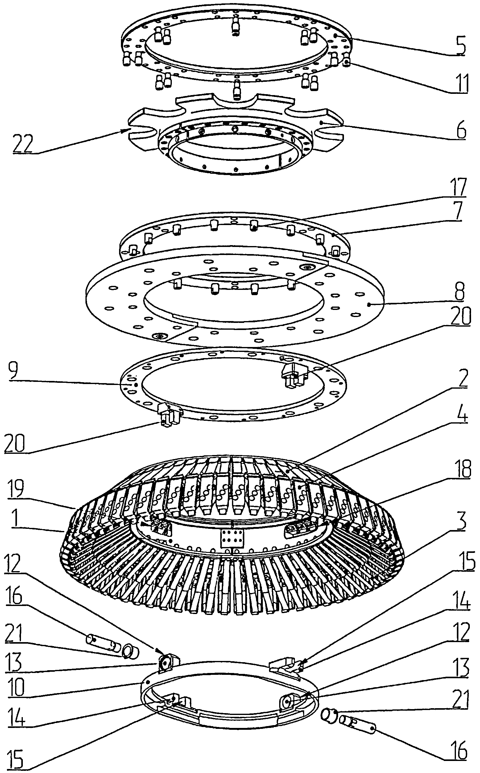
На фиг.4 изображен узел подвески кольца датчиков транспортного модуля дефектоскопа внутритрубного в разобранном состоянии.Figure 4 shows the node of the suspension ring of the sensors of the transport module of the in-tube flaw detector in the disassembled state.
На фиг.5 изображена замкнутая направляющая овальной формы.Figure 5 shows a closed guide oval.
На фиг.6 изображен транспортный модуль магнитный дефектоскопа внутритрубного в качестве примера использования заявленного узла подвески кольца датчиков.Figure 6 shows the transport module magnetic flaw detector in-pipe as an example of the use of the claimed node of the suspension ring of the sensors.
На фигурах 1-6 приняты следующие обозначения:In figures 1-6, the following notation:
1 - кольцо датчиков;1 - a ring of sensors;
2 - рычаг;2 - lever;
3 - пружина пластинчатая;3 - leaf spring;
4 - измерительный датчик;4 - measuring sensor;
5 - первый подвижный фланец;5 - the first movable flange;
6 - неподвижный фланец;6 - fixed flange;
7 - второй подвижный фланец;7 - second movable flange;
8 - полиуретановое кольцо;8 - polyurethane ring;
9 - третий подвижный фланец;9 - the third movable flange;
10 - замкнутая направляющая овальной формы;10 - closed guide oval;
11 - первая стойка;11 - the first rack;
12 - первый выступ (замкнутой направляющей овальной формы);12 - the first protrusion (closed guide oval);
13 - отверстие (первого выступа замкнутой направляющей овальной формы);13 - hole (first protrusion of a closed guide oval);
14 - второй выступ (замкнутой направляющей овальной формы);14 - the second protrusion (closed guide oval);
15 - направляющий паз (второго выступа замкнутой направляющей овальной формы);15 - guide groove (second protrusion of a closed guide oval);
16 - металлическая ось;16 - metal axis;
17 - вторая стойка;17 - the second rack;
18 - первое прямоугольное отверстие (кольца датчиков);18 - the first rectangular hole (sensor rings);
19 - второе прямоугольное отверстие (кольца датчиков);19 - the second rectangular hole (sensor rings);
20 - ползун (третьего подвижного фланца);20 - slider (third movable flange);
21 - втулка;21 - sleeve;
22 - выборка (неподвижного фланца);22 - sample (fixed flange);
23 - малая ось симметрии замкнутой направляющей овальной формы;23 - a small axis of symmetry of a closed guide oval;
24 - большая ось симметрии замкнутой направляющей овальной формы;24 - the major axis of symmetry of the closed guide is oval;
25 - корпус транспортного модуля дефектоскопа;25 - housing of the transport module of the flaw detector;
26 - узел подвески кольца датчиков транспортного модуля дефектоскопа внутритрубного;26 - the node of the suspension ring of the sensors of the transport module of the in-pipe flaw detector;
27 - направление движения дефектоскопа.27 - the direction of movement of the flaw detector.
Предлагаемая конструкция представляет собой систему трех подвижных фланцев 5, 7 и 9, замкнутой направляющей овальной формы 10, полиуретанового кольца 8 и неподвижного фланца 6 с выборками 22. Фланец 6 при сборке подвески кольца датчиков неподвижно закрепляется на корпус 25 одного из транспортных модулей в составе дефектоскопа. Первый подвижный фланец 5 и второй подвижный фланец 7, через выборки 22 неподвижного фланца 6, соединяются между собой с помощью первых стоек 11. Первый и второй подвижные фланцы 5 и 7 образуют зазор, величина которого зависит от величины первых стоек 11. Зазор между первым и вторым подвижными фланцами 5 и 7 обеспечивает всей подвеске датчиков 26 степень свободы в плоскости перпендикулярной оси симметрии транспортного модуля дефектоскопа, а также ограничивает свободу подвески датчиков 26 в продольном направлении. Третий подвижный фланец 9 с помощью вторых стоек 17 соединяется со вторым подвижным фланцем 7. Между подвижными фланцами 7 и 9 зажимается полиуретановое кольцо 8. Наружный диаметр полиуретанового кольца 8 выполнен равным по размеру внутреннему диаметру трубопровода, что позволяет центрировать подвеску датчиков 26, относительно поперечного сечения трубопровода. К третьему подвижному фланцу крепиться кольцо датчиков 1. Закрепленные между собой подвижные фланцы 5, 7 и 9, полиуретановое кольцо 8 и кольцо датчиков 1 имеют диаметр центральных отверстий, превышающий наружный диаметр цилиндрического корпуса транспортного модуля дефектоскопа в месте установки узла подвески кольца датчиков 26.The proposed design is a system of three
На кольце датчиков 1, осесимметрично размещены шарнирно закрепленные рычаги с измерительными датчиками и пружинами (например, пластинчатыми, обеспечивающими прижатие измерительных датчиков к стенке трубопровода). В кольце датчиков 1 выполнены два расположенных под углом 180 градусов относительно друг друга первых прямоугольных отверстия 18 и два расположенных под углом 180 градусов относительно друг друга вторых прямоугольных отверстия 19. Угол между двумя парами отверстий 19 и 18 составляет 90 градусов. Кольцо датчиков 1, посредством первых прямоугольных отверстий 18, совмещено с металлическими осями 16. Кольцо датчиков 1, посредством вторых прямоугольных отверстий 19, совмещено с ползуном 20 третьего подвижного фланца 9. Внутри кольца датчиков 1 размещена замкнутая направляющая овальной формы 10. Замкнутая направляющая овальной формы 10 имеет две пары выступов 12 и 14. Первые два выступа 12 замкнутой направляющей овальной формы 10 предназначены для взаимодействия с металлическими осями 16, посредством соосных отверстий. Металлические оси 16 неподвижно закрепляются на корпусе транспортного модуля перпендикулярно оси симметрии транспортного модуля дефектоскопа 13. Вторые два выступа 14, смещенные относительно двух первых выступов 12 на 90 градусов, имеют направляющие пазы 15 и предназначены для взаимодействия с ползунами 20 третьего подвижного фланца 9.On the ring of
Конструкция узла подвески кольца датчиков транспортного модуля дефектоскопа работает следующим образом. При движении дефектоскопа по направлению 27, закрепленные между собой фланцы 5, 7 и 9 и кольцо датчиков 1 перемещаются в плоскости перпендикулярной осисимметрии транспортного модуля дефектоскопа, под действием усилия создаваемого полиуретановым диском 8. Перемещение кольца датчиков в плоскости, перпендикулярной оси симметрии транспортного модуля дефектоскопа и неизменное угловое положение, относительно внутренней стенки трубопровода, обеспечивается возможностью перемещения кольца датчиков 1 вдоль большой оси 24, замкнутой направляющей овальной формы, за счет совмещения первых прямоугольных отверстий 18 с металлическими осями 16, и перемещения вдоль малой оси 23, замкнутой направляющей овальной формы, за счет совмещения вторых прямоугольных отверстий 19 с ползуном 20 третьего подвижного фланца 9 взаимодействующего с направляющим пазом 15 второго выступа 14 замкнутой направляющей овальной формы.The design of the suspension unit of the ring of sensors of the transport module of the flaw detector is as follows. When the flaw detector moves in
Технический результат достигается за счет уменьшения количества взаимодействующих между собой фланцев, что позволяет уменьшить продольный размер транспортного модуля, при этом сохраняя, постоянный контакт измерительных датчиков со стенкой трубопровода, за счет работы центрирующего полиуретанового кольца и неизменность углового положения кольца датчиков, за счет взаимодействия прямоугольных отверстий кольца датчиков с элементами третьего подвижного фланца и замкнутого кольца овальной формы.The technical result is achieved by reducing the number of interacting flanges, which allows to reduce the longitudinal size of the transport module, while maintaining constant contact of the measuring sensors with the pipe wall, due to the centering polyurethane ring and the invariance of the angular position of the sensor ring, due to the interaction of rectangular holes sensor rings with elements of a third movable flange and a closed oval-shaped ring.
Пример реализации заявленного узла подвески кольца датчиков 26 на корпусе транспортного модуля дефектоскопа внутритрубного 25 приведен на фиг.6.An example of the implementation of the claimed node of the suspension ring of the
Claims (5)
Priority Applications (1)
| Application Number | Priority Date | Filing Date | Title |
|---|---|---|---|
| RU2012121301/28U RU123961U1 (en) | 2012-05-24 | 2012-05-24 | TRANSPORT SENSOR RING SUSPENSION UNIT TUBES |
Applications Claiming Priority (1)
| Application Number | Priority Date | Filing Date | Title |
|---|---|---|---|
| RU2012121301/28U RU123961U1 (en) | 2012-05-24 | 2012-05-24 | TRANSPORT SENSOR RING SUSPENSION UNIT TUBES |
Publications (1)
| Publication Number | Publication Date |
|---|---|
| RU123961U1 true RU123961U1 (en) | 2013-01-10 |
Family
ID=48807518
Family Applications (1)
| Application Number | Title | Priority Date | Filing Date |
|---|---|---|---|
| RU2012121301/28U RU123961U1 (en) | 2012-05-24 | 2012-05-24 | TRANSPORT SENSOR RING SUSPENSION UNIT TUBES |
Country Status (1)
| Country | Link |
|---|---|
| RU (1) | RU123961U1 (en) |
-
2012
- 2012-05-24 RU RU2012121301/28U patent/RU123961U1/en active
Similar Documents
| Publication | Publication Date | Title |
|---|---|---|
| CN105716555B (en) | Device and method for measuring the displacement between two substantially coaxial components | |
| JP4750152B2 (en) | Flexible array probe for inspection of contour surfaces with various cross-sectional shapes | |
| CN103512483B (en) | Overhead pipe wall thickness corrosion scanning and detecting system | |
| JP6006990B2 (en) | Eddy current testing probe | |
| CN105637358A (en) | Portable ultrasonic flow detection device and ultrasonic flow detection method | |
| RU2697007C1 (en) | Device for in-pipe diagnostics of pipeline technical state | |
| RU123961U1 (en) | TRANSPORT SENSOR RING SUSPENSION UNIT TUBES | |
| CN202583133U (en) | Clamp for ultrasonic through measuring probe for pipeline | |
| JP5829674B2 (en) | Ultrasonic inspection apparatus for tube and ultrasonic inspection method for tube | |
| KR100638997B1 (en) | Magnetic flux leakage pig and sensor module installed at the magnetic flux leakage | |
| CN110207779B (en) | Parameterization mounting method for externally-clamped sensor | |
| RU113006U1 (en) | SECONDARY DEFECTOSCOPE SENSOR MOUNTING UNIT | |
| JP5687021B2 (en) | Calibration method, calibration jig and tube inspection method | |
| KR101382051B1 (en) | Apparatus for detecting ovality of heat exchanger tube and method thereof | |
| RU220375U1 (en) | DEVICE FOR CONTROL OF RING WELDED JOINTS OF PIPELINES | |
| CN210719656U (en) | Large-scale wave water tank pipeline vortex-induced vibration experimental device | |
| RU227538U1 (en) | Pipe ellipticity measuring device | |
| BRPI0803388A2 (en) | endoscopic stereoscopic system | |
| RU2561317C2 (en) | Device for measurement of axial runout of bearing cup | |
| RU2298784C1 (en) | Mechanism for fastening detector to case of intra-tube flaw detector | |
| JP2012122979A (en) | Measuring fixture and method for measuring cross sectional shape of pipe | |
| RU2379674C1 (en) | Pipeline analysis and diagnostics device | |
| RU220379U1 (en) | MONITORING DEVICE FOR REACTOR PLANT EQUIPMENT CASES | |
| CN108278947A (en) | A kind of detecting tool of flute profile fixture | |
| RU2641618C1 (en) | Metrological ground |
Legal Events
| Date | Code | Title | Description |
|---|---|---|---|
| PD1K | Correction of name of utility model owner |