RU121942U1 - DOPPLER METEOROLOGICAL RADAR DOLAR "DMRL-S" - Google Patents
DOPPLER METEOROLOGICAL RADAR DOLAR "DMRL-S" Download PDFInfo
- Publication number
- RU121942U1 RU121942U1 RU2012110972/08U RU2012110972U RU121942U1 RU 121942 U1 RU121942 U1 RU 121942U1 RU 2012110972/08 U RU2012110972/08 U RU 2012110972/08U RU 2012110972 U RU2012110972 U RU 2012110972U RU 121942 U1 RU121942 U1 RU 121942U1
- Authority
- RU
- Russia
- Prior art keywords
- signals
- meteorological
- transmitter
- doppler
- frequency
- Prior art date
Links
Classifications
-
- Y—GENERAL TAGGING OF NEW TECHNOLOGICAL DEVELOPMENTS; GENERAL TAGGING OF CROSS-SECTIONAL TECHNOLOGIES SPANNING OVER SEVERAL SECTIONS OF THE IPC; TECHNICAL SUBJECTS COVERED BY FORMER USPC CROSS-REFERENCE ART COLLECTIONS [XRACs] AND DIGESTS
- Y02—TECHNOLOGIES OR APPLICATIONS FOR MITIGATION OR ADAPTATION AGAINST CLIMATE CHANGE
- Y02A—TECHNOLOGIES FOR ADAPTATION TO CLIMATE CHANGE
- Y02A90/00—Technologies having an indirect contribution to adaptation to climate change
- Y02A90/10—Information and communication technologies [ICT] supporting adaptation to climate change, e.g. for weather forecasting or climate simulation
Abstract
1. Допплеровский метеорологический радиолокатор, содержащий последовательно соединенные передатчик, устройство поляризации СВЧ-сигналов и антенный переключатель, соединенный по сигналам зондирования с приемопередающей антенной и по отраженным метеорологическим сигналам - с четырехканальным радиоприемником, цифровой выход которого соединен с ЭВМ управления и обработки метеорологических сигналов, отличающийся тем, что он дополнительно содержит измеритель мощности излучения передатчика, измеритель чувствительности радиоприемника и формирователь пачек разночастотных узкополосных и широкополосных зондирующих сигналов, причем передатчик выполнен усилительным и соединен по входу с формирователем пачек зондирующих сигналов, а по второму выходу - с входом измерителя мощности излучения передатчика, цифровой выход которого соединен с первым входом ЭВМ, второй и третий управляющие выходы которой соединены с соответствующими управляющими входами формирователя пачек зондирующих сигналов, а измеритель чувствительности радиоприемника по аналоговым входам/выходам измерительного сигнала - с соответствующими входами/выходами каналов радиоприемника, а по результатам измерений разъюстировки каналов - с соответствующим входом ЭВМ. ! 2. Допплеровский метеорологический радиолокатор по п.1, отличающийся тем, что передатчик выполнен в виде усилительного пролетного клистрона или твердотельного транзисторного усилителя. ! 3. Допплеровский метеорологический радиолокатор по п.1, отличающийся тем, что формирователь пачек разночастотных узкополосных и широкополосных зондирующих сигналов содержит задающий СВЧ-ге� 1. Doppler meteorological radar containing a serially connected transmitter, a polarization device for microwave signals and an antenna switch connected via sensing signals to a transceiving antenna and reflected meteorological signals to a four-channel radio receiver, the digital output of which is connected to a computer for controlling and processing meteorological signals, which differs the fact that it further comprises a transmitter radiation power meter, a radio receiver sensitivity meter a shaper of bundles of different frequency narrow-band and broadband probing signals, the transmitter being amplified and connected at the input to the shaper of bursts of sounding signals, and at the second output, to the input of the transmitter radiation power meter, the digital output of which is connected to the first computer input, the second and third control outputs of which connected to the corresponding control inputs of the shaper bundle of probing signals, and the sensitivity meter of the radio receiver by analog inputs / outputs itelnogo signal - to the corresponding inputs / outputs of the radio channels, and the results of the misalignment measurement channels - the corresponding input of the computer. ! 2. The Doppler weather radar according to claim 1, characterized in that the transmitter is made in the form of an amplification span klystron or solid-state transistor amplifier. ! 3. The Doppler meteorological radar according to claim 1, characterized in that the shaper of the bundles of different frequency narrowband and broadband probing signals contains a master microwave
Description
Область техники. Полезная модель относится к метеорологии, конкретно к допплеровским метеорологическим радиолокаторам с двойной поляризацией.The field of technology. The utility model relates to meteorology, specifically to double-polarized Doppler meteorological radars.
Уровень техники. Известны допплеровские метеорологических радиолокаторов /1-15/, далее метеолокаторы, использующих поляризованные зондирующие сигналы.The level of technology. Known Doppler meteorological radars / 1-15 /, then weather radars using polarized sounding signals.
Наиболее близким по назначению и технической сущности полезной модели относится допплеровский метеорологический радиолокатор /15/, содержащий последовательно соединенные передатчик, устройство поляризации СВЧ-сигналов и антенный переключатель, соединенный по сигналам зондирования с приемо-передающей антенной и по отраженным метеорологическим сигналам - с четырехканальным радиоприемником, цифровой выход которого соединен с ЭВМ управления и обработки метеорологических сигналов.The closest in purpose and technical essence of the utility model is the Doppler meteorological radar / 15 / containing a serially connected transmitter, a device for polarizing microwave signals and an antenna switch connected via sensing signals to a transmitting and receiving antenna and reflected meteorological signals to a four-channel radio receiver, whose digital output is connected to a computer for controlling and processing meteorological signals.
При этом передатчик выполнен генераторным и содержит два узкополосных импульсных СВЧ-генератора (магнетроны или генераторные клистроны), разнесенные между собой по несущей частоте. Приемопередающая антенна выполнена рефлекторной с диаграммой направленности игольчатого типа и установлена на карданном подвесе с возможностью одновременного сканирования приземного слоя атмосферы ортогонально поляризованными лучами на двух различных частотах по азимуту и углу места под управлением ЭВМ.In this case, the transmitter is made generator and contains two narrow-band pulsed microwave generators (magnetrons or generator klystrons), spaced from each other along the carrier frequency. The transceiver antenna is made reflective with a needle-type radiation pattern and mounted on a gimbal with the ability to simultaneously scan the surface layer of the atmosphere with orthogonally polarized beams at two different frequencies in azimuth and elevation under computer control.
Недостатком этого метеолокатора является относительно невысокая точность выдаваемых метеоданных и прогноза погоды, связанная с относительно высокими ошибками поляризационных измерений и юстировки каналов радиоприемника и передатчика.The disadvantage of this weather radar is the relatively low accuracy of the issued weather data and weather forecast, associated with relatively high errors in polarization measurements and alignment of the channels of the radio receiver and transmitter.
Задачей полезной модели является повышение точности выдаваемых метеоданных и прогноза погоды.The objective of the utility model is to increase the accuracy of the issued weather data and weather forecast.
Техническим результатом, обеспечивающим решение этой задачи, является снижение ошибок поляризационных измерений и юстировки каналов радиоприемника и передатчика радиолокатора.The technical result that provides the solution to this problem is to reduce the errors of polarization measurements and alignment of the channels of the radio receiver and the radar transmitter.
Достижение заявленного технического результата и, как следствие, решение поставленной задачи достигается тем, что допплеровский метеорологический радиолокатор с двойной поляризацией, содержащий последовательно соединенные передатчик, устройство поляризации СВЧ-сигналов и антенный переключатель, соединенный по сигналам зондирования с приемо-передающей антенной и по отраженным метеорологическим сигналам - с четырехканальным радиоприемником, цифровой выход которого соединен с ЭВМ управления и обработки метеорологических сигналов, согласно полезной модели он дополнительно содержит измеритель мощности излучения передатчика, измеритель чувствительности радиоприемника и формирователь пачек разночастотных узкополосных и широкополосных зондирующих сигналов, причем передатчик выполнен усилительным и соединен по входу с формирователем пачек зондирующих сигналов, а по второму выходу - с входом измерителя мощности излучения передатчика, цифровой выход которого соединен с первым входом ЭВМ, второй и третий управляющие выходы которой соединены с соответствующими управляющими входами формирователя пачек зондирующих сигналов, а измеритель чувствительности радиоприемника по аналоговым входам/выходам измерительного сигнала - с соответствующими входами/выходами каналов радиоприемника.The achievement of the claimed technical result and, as a result, the solution of the problem is achieved by the fact that the Doppler meteorological radar with double polarization, containing a series-connected transmitter, a polarization device for microwave signals and an antenna switch connected by sensing signals to a receiving-transmitting antenna and reflected meteorological signals - with a four-channel radio receiver, the digital output of which is connected to a computer for controlling and processing meteorological signals, According to the utility model, it further comprises a transmitter radiation power meter, a radio sensitivity meter and a packet shaper of different frequency narrowband and broadband probe signals, the transmitter being amplified and connected at the input to the probe packet shaper, and at the second output to the transmitter radiation power meter input, the digital output of which is connected to the first input of the computer, the second and third control outputs of which are connected to the corresponding control the influential inputs of the shaper of the bundles of probing signals, and the sensitivity meter of the radio receiver by analogue inputs / outputs of the measuring signal with the corresponding inputs / outputs of the channels of the radio receiver.
При этом передатчик выполнен в виде усилительного пролетного клистрона или твердотельного транзисторного усилителя. Формирователь пачек разночастотных узкополосных и широкополосных зондирующих сигналов содержит задающий СВЧ - генератор и двухчастотный генератор промежуточной частоты, соединенные по выходу через смеситель с сигнальным входом усилительного передатчика. Двухчастотный генератор промежуточной частоты содержит последовательно соединенные цифровой генератор коротких и длинных импульсов промежуточной частоты и цифроаналоговый преобразователь. Короткий и длинный импульсы генератора разнесены по частоте на величину ΔF, короткий импульс промежуточной частоты выполнен немодулированным, а длинный импульс - с внутриимпульсной модуляцией, длительность коротких τ1 и длинных τ2 импульсов промежуточной частоты, разнос их частот, а также временная пауза Т между ними выбраны из условий:In this case, the transmitter is made in the form of an amplification span klystron or solid-state transistor amplifier. The shaper packs of multi-frequency narrow-band and wide-band probe signals contains a master microwave generator and a two-frequency intermediate frequency generator, connected at the output through the mixer with the signal input of the amplifier transmitter. The two-frequency intermediate frequency generator contains a digitally connected short and long pulse generator of the intermediate frequency and a digital-to-analog converter. The short and long pulses of the generator are spaced apart in frequency by ΔF, the short pulse of the intermediate frequency is unmodulated, and the long pulse is with intrapulse modulation, the duration of short τ 1 and long τ 2 pulses of the intermediate frequency, the spacing of their frequencies, and also the time pause T between them selected from the conditions:
τ1≈{τ2}сж; {τ2}сж<<τ2; T≥τ1+τ2,τ 1 ≈ {τ 2 } squ ; {τ 2 } cr << τ 2 ; T≥τ 1 + τ 2 ,
ΔF=F2-F1=1÷10 МГц, , ΔfЄ{1÷Δfmax},ΔF = F 2 -F 1 = 1 ÷ 10 MHz, , ΔfЄ {1 ÷ Δf max },
где: {τ2}сж - длительность сжатого широкополосного (с внутриимпульсной модуляцией) сигнала;where: {τ 2 } squ - the duration of the compressed broadband (with intrapulse modulation) signal;
F1 - частота короткого немодулированного импульса;F 1 - frequency of a short unmodulated pulse;
F2 - текущая частота длинного с внутриимпульсной модуляцией импульса;F 2 - the current frequency of a long pulse with intrapulse modulation of the pulse;
- центральное значение величины F2; - the central value of the value of F 2 ;
Δf, Δfmax - текущее и максимально допустимое значение девиации (отклонения) частоты F2 от ее центрального значения .Δf, Δf max - the current and maximum allowable value of the deviation (deviation) of the frequency F 2 from its central value .
Приемо-передающая антенна выполнена параболической с игольчатым лучом и азимутально-угломестным электроприводом, в виде линейной фазированной антенной решетки - облучателя со сканированием по углу места, вертикально ориентированной в фокусе параболического рефлектора, снабженного азимутальным электроприводом или в виде прямоугольной фазированной антенной решетки с электронным сканированием по азимуту и углу места под управлением ЭВМ. Приемо-передающая антенна содержит один канал с горизонтальной и/или один канал с вертикальной поляризацией, причем каждый поляризационный канал соединен по отраженным эхосигналам с двумя соответствующими каналами четырехканального радиоприемника. Для снижения искажений принятых эхосигналов приемник содержит по каждой поляризации эхосигналов аттенюатор, нагруженный без ослабления на основной приемный канал и с ослаблением на 20÷40 дБ - на дополнительный приемный канал, причем каждый канал содержит последовательно соединенные супергетеродинный приемник с цифровым выходом, цифровой фазовый детектор и устройство цифровой обработки сигналов, снабженное программами фильтрации несинхронных импульсных помех, сжатия широкополосных сигналов и спектральной обработки принятых сигналов. ЭВМ управления и обработки метеорологических сигналов содержит блок управления и первичной обработки метеорологической информации и блок вторичной обработки метеорологической информации, соединенные между собой кабельной или радио линией интерфейсной связи. Блок управления и первичной обработки метеорологической информации снабжен программой привязки результатов измерений по отражаемости, радиальной скорости ширине спектра к пространственным координатам, а блок вторичной обработки - программой идентификации результатов первичной обработки сигналов программой преобразования идентифицированных метеоданных в форму удобную для их трансляции потребителям метеоданных на их абонентские пункты. Блок первичной обработки метеорологической информации снабжен приемником ГЛОНАСС/GPS для синхронизации метеорологических измерений и передачи метеоданных в системе единого времени.The transmitting and receiving antenna is made parabolic with a needle beam and an azimuth-elevation electric drive, in the form of a linear phased antenna array — an irradiator with scanning along the elevation angle, vertically oriented at the focus of a parabolic reflector equipped with an azimuthal electric drive or in the form of a rectangular phased antenna array with electronic scanning along azimuth and elevation under computer control. The transmit-receive antenna contains one channel with horizontal and / or one channel with vertical polarization, each polarization channel being connected via reflected echo signals to two corresponding channels of a four-channel radio receiver. To reduce the distortion of the received echo signals, the receiver contains an attenuator for each echo polarization, loaded without attenuation to the main receiving channel and attenuated by 20 ÷ 40 dB to an additional receiving channel, each channel containing a superheterodyne receiver with a digital output connected in series, a digital phase detector, and digital signal processing device equipped with programs for filtering non-synchronous impulse noise, compressing broadband signals and spectral processing of received signals . The computer for controlling and processing meteorological signals comprises a control and primary processing unit for meteorological information and a secondary processing unit for meteorological information, interconnected by a cable or radio interface communication line. The control unit and the primary processing of meteorological information is equipped with a program for linking the measurement results for reflectivity, the radial velocity of the spectral width to spatial coordinates, and the secondary processing unit is equipped with a program for identifying the results of the primary signal processing, a program for converting the identified weather data into a form convenient for their transmission to weather consumers at their subscriber stations . The primary meteorological information processing unit is equipped with a GLONASS / GPS receiver for synchronizing meteorological measurements and transmitting meteorological data in a single time system.
Введение измерителя мощности излучения передатчика и измерителя чувствительности радиоприемника и их соответствующее подключение к ЭВМ позволяют уменьшить ошибки юстировки каналов передатчика и приемника путем измерения разъюстировки каналов по мощности и чувствительности и вычитания их из результатов измерений метеоданных и, тем самым, - повысить точность выдаваемых метеоданных и прогноза погоды.The introduction of a transmitter radiation power meter and a radio receiver sensitivity meter and their corresponding connection to a computer make it possible to reduce the alignment errors of the transmitter and receiver channels by measuring the misalignment of the channels by power and sensitivity and subtracting them from the meteorological measurements and, thereby, improve the accuracy of the weather data and forecast the weather.
Введение формирователя пачек двухчастотных узкополосных и широкополосных зондирующих сигналов, выполнение передатчика усилительным и соответствующее их соединение позволяет увеличить точность измерений измерения поляризационных параметров атмосферы за счет расширения спектра зондирующих сигналов и одновременно позволяет перекрыть все дальности от минимальной (сотни метров с помощью узкополосных сигналов) до максимальной (сотни км с помощью широкополосных сигналов) при сохранении требуемой точности измерений и прогноза погоды.The introduction of a shaper of bundles of dual-frequency narrow-band and wide-band probe signals, the implementation of a transmitter as amplifying and their corresponding connection allows to increase the accuracy of measurements of the polarization parameters of the atmosphere by expanding the spectrum of the probing signals and at the same time allows to cover all ranges from the minimum (hundreds of meters using narrow-band signals) to the maximum ( hundreds of km using broadband signals) while maintaining the required measurement accuracy and weather forecast.
Рациональный выбор длительностей импульсов, периода их следования, их спектров и рациональный разнос несущих частот широкополосных и узкополосных импульсов дополнительно позволяет снизить взаимное влияние зондирующих и эхосигналов на процесс измерений поляризационных характеристик метеорологических образований в атмосфере и, тем самым, дополнительно увеличить точность выдаваемых метеоданных и прогноза погоды.The rational choice of pulse durations, their repetition periods, their spectra and the rational spacing of the carrier frequencies of broadband and narrowband pulses additionally reduces the mutual influence of probing and echo signals on the measurement process of the polarization characteristics of meteorological formations in the atmosphere and, thereby, further increase the accuracy of the generated weather data and weather forecast .
В целом указанные технические преимущества позволяют достичь заявленного технического результата и, как следствие, - решить поставленную техническую задачу.In general, the indicated technical advantages make it possible to achieve the claimed technical result and, as a result, to solve the technical problem.
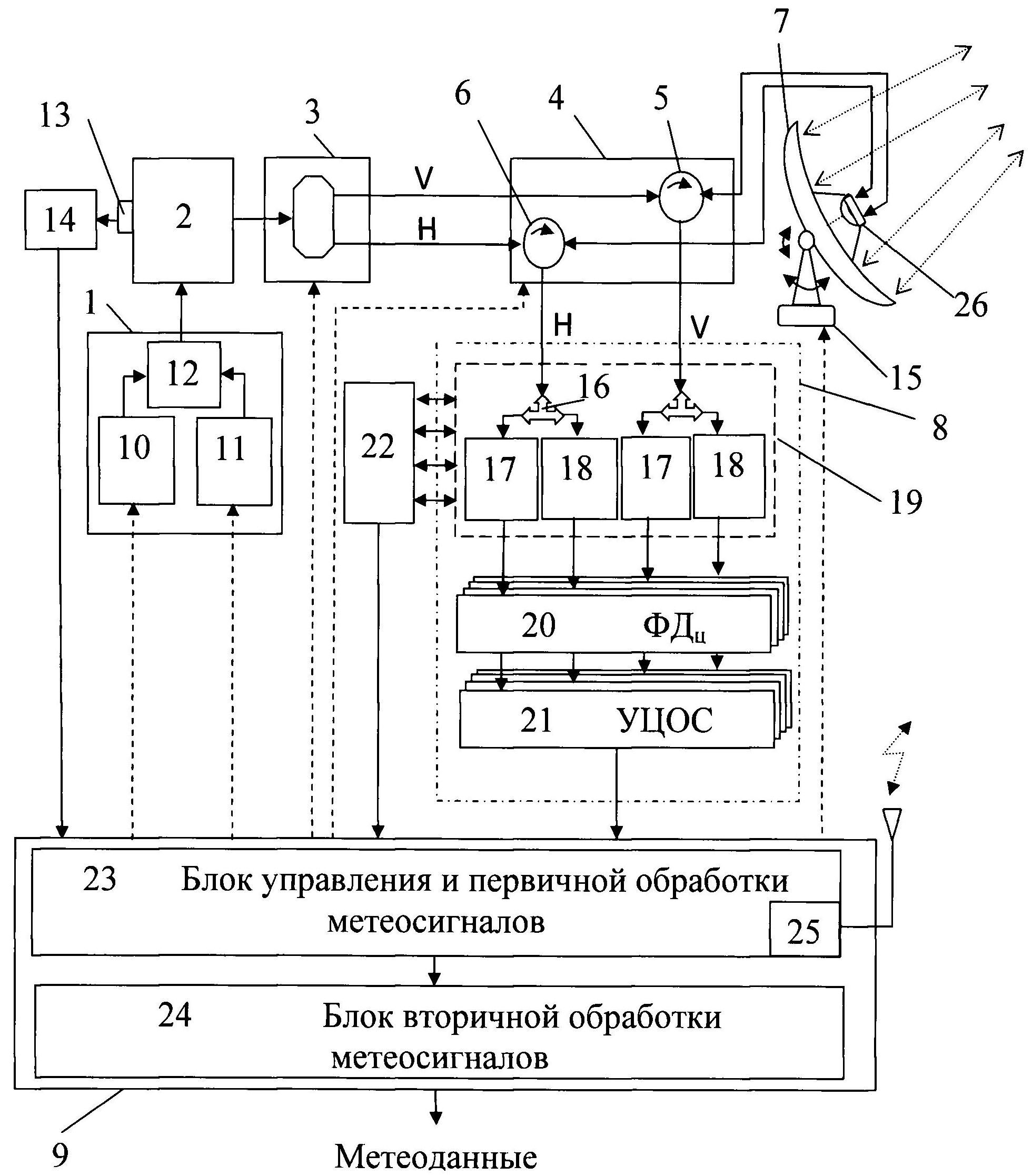
На фигуре представлена функциональная схема допплеровского метеорологического радиолокатора с двойной поляризацией.The figure shows a functional diagram of a Doppler meteorological radar with double polarization.
Описание в статике. Допплеровский метеорологический радиолокатор (метеолокатор) с двойной поляризацией содержит последовательно соединенные формирователь 1 пачек разночастотных узкополосных и широкополосных зондирующих сигналов, усилительный широкополосный передатчик 2, устройство 3 поляризации СВЧ - сигналов и антенный переключатель 4. Переключатель 4 в простейшем случае содержит два СВЧ-циркулятора 5 и 6, соединенные по сигналам зондирования с приемо-передающей антенной 7 и по отраженным метеорологическим сигналам - с четырехканальным радиоприемником 8. Цифровой выход радиоприемника 8 соединен с ЭВМ 9 управления и обработки метеорологических сигналов. Формирователь 1 пачек разночастотных узкополосных и широкополосных зондирующих сигналов содержит задающий СВЧ-генератор 10 и двухчастотный генератор 11 промежуточной частоты, соединенные по выходу через смеситель 12 с сигнальным входом усилительного передатчика 2. Двухчастотный генератор 11 промежуточной частоты содержит последовательно соединенные цифровой генератор коротких и длинных импульсов промежуточной частоты и цифроаналоговый преобразователь (на фигурах не показано). Короткий и длинный импульсы генератора 11 разнесены по частоте на величину ΔF, короткий импульс промежуточной частоты выполнен немодулированным, а длинный импульс - с внутриимпульсной модуляцией. Длительность коротких τ1 и длинных τ2 импульсов промежуточной частоты, разнос их частот, а также временная пауза T между ними выбраны из условий:Description in statics. A double-polarized Doppler meteorological radar (meteorological radar) contains serially connected shaper 1 packs of multi-frequency narrowband and broadband probing signals, an amplifying broadband transmitter 2, a device for polarizing microwave signals and an antenna switch 4. Switch 4 in the simplest case contains two microwave circulators 5 and 6, connected by sensing signals with a transceiver antenna 7 and by reflected meteorological signals with a four-channel radio 8 The digital output of the radio 8 is connected to a computer 9 for controlling and processing meteorological signals. Shaper 1 packs of multi-frequency narrow-band and wide-band probe signals contains a master microwave generator 10 and a two-frequency intermediate frequency generator 11 connected at the output through a mixer 12 to the signal input of the amplification transmitter 2. A two-frequency intermediate frequency generator 11 contains a digital short and long pulse generator intermediate connected in series frequency and digital-to-analog converter (not shown in the figures). The short and long pulses of the generator 11 are spaced in frequency by ΔF, the short pulse of the intermediate frequency is unmodulated, and the long pulse is with intrapulse modulation. The duration of short τ 1 and long τ 2 pulses of intermediate frequency, the spacing of their frequencies, as well as a temporary pause T between them are selected from the conditions:
где: {τ2}сж - длительность сжатого широкополосного (с внутриимпульсной модуляцией) сигнала;where: {τ 2 } squ - the duration of the compressed broadband (with intrapulse modulation) signal;
F1 - частота короткого немодулированного импульса;F 1 - frequency of a short unmodulated pulse;
F2 - текущая частота длинного с внутриимпульсной модуляцией импульса;F 2 - the current frequency of a long pulse with intrapulse modulation of the pulse;
- центральное значение величины F2; - the central value of the value of F 2 ;
Δf, Δfmax - текущее и максимально допустимое значение девиации (отклонения) частоты F2 от ее центрального значения .Δf, Δf max - the current and maximum allowable value of the deviation (deviation) of the frequency F 2 from its central value .
где: {τ2}сж - длительность сжатого широкополосного сигнала.where: {τ 2 } squ - the duration of the compressed broadband signal.
Численное значение величин τ1 и τ2, в выражении (1) может составлять соответственно единицы и сотни мкс. Широкополосный длинный импульс τ2 с внутриимпульсной модуляцией может быть выполнен в виде фазо-кодо-манипулированных (ФКМ), линейно-частотно-модулированных (ЛЧМ) сигналов или в виде других сложных сигналов с внутриимпульсной модуляцией.The numerical value of the values of τ 1 and τ 2 in the expression (1) can be respectively units and hundreds of microseconds. The broadband long pulse τ 2 with intrapulse modulation can be made in the form of phase-code-shift keyed (PCM), linear frequency-modulated (LFM) signals or in the form of other complex signals with intrapulse modulation.
Задающий СВЧ-генератор 10 и двухчастотный генератор 11 промежуточной частоты соединены по управляющим входам с ЭВМ 9, а по выходам через смеситель 12 с сигнальным входом передатчика 2. Передатчик 2 выполнен в виде широкополосного усилителя мощности на основе усилительного пролетного клистрона или твердотельного усилителя мощности. СВЧ-выход усилительного передатчика 2 соединен с поляризатором 3 непосредственно и через аттенюатор 13 с заданным коэффициентом ослабления с аналоговым входом измерителя 14 мощности. Измеритель 14 мощности выполнен в виде последовательно соединенных детектора и цифрового измерителя импульсной мощности зондирующих сигналов, соединенного по выходу с сигнальным входом ЭВМ 9. Поляризатор 3 выполнен в виде ферритового преобразователя поляризации СВЧ - излучения или в виде СВЧ - делителя мощности, нагруженного на ортогонально ориентированные (вертикально и горизонтально) Е - волноводы с прямоугольным сечением. Выходы поляризатора 3 с вертикальной V - поляризацией и горизонтальной Н - поляризацией соединены с первыми входами циркуляторов 5 и 6. Циркуляторы 5 и 6 соединены по сигналам зондирования с приемо-передающей антенной 7 и по отраженным метеорологическим сигналам - с четырехканальным радиоприемником 8. Антенна 7 выполнена в виде параболической антенны с игольчатым лучом, снабженной азимутальным и угломестным электроприводом 15. При других вариантах исполнения антенна 7 может быть выполнена в виде линейной фазированной антенной решетки, установленной вертикально в фокусе рефлектора и с электронным сканированием по углу места, а также электромеханическим сканированием по азимуту. Возможно исполнение антенны 7 в виде прямоугольной фазированной антенной решетки с электронным сканированием по азимуту и углу места под управлением ЭВМ. Выходы циркуляторов 5 и 6 по эхосигналам каждой поляризации Н и V нагружены на четырехканальный радиоприемник 8. Для снижения искажений принятых эхосигналов радиоприемник 8 содержит по каждой поляризации Н и V эхосигналов аттенюатор 16, нагруженный без ослабления на основной приемный канал 17 и с ослаблением на 20 -40 дБ - на дополнительный приемный канал 18.The master microwave generator 10 and the two-frequency intermediate frequency generator 11 are connected at the control inputs to the computer 9, and at the outputs through the mixer 12 to the signal input of the transmitter 2. The transmitter 2 is made in the form of a broadband power amplifier based on an amplification span klystron or solid-state power amplifier. The microwave output of the amplifier transmitter 2 is connected to the polarizer 3 directly and through the attenuator 13 with a given attenuation coefficient with the analog input of the power meter 14. The power meter 14 is made in the form of a series-connected detector and a digital pulse power meter of the probing signals, connected at the output to the signal input of the computer 9. The polarizer 3 is made in the form of a ferrite converter for polarizing microwave radiation or in the form of a microwave power divider loaded on orthogonally oriented ( vertically and horizontally) E - waveguides with a rectangular cross section. The outputs of the polarizer 3 with vertical V - polarization and horizontal H - polarization are connected to the first inputs of the circulators 5 and 6. The circulators 5 and 6 are connected by sensing signals to the transmitting and receiving antenna 7 and, by reflected meteorological signals, to a four-channel radio receiver 8. Antenna 7 is made in the form of a parabolic antenna with a needle beam, equipped with an azimuthal and elevation electric drive 15. In other embodiments, the antenna 7 can be made in the form of a linear phased antenna array lennoy vertically in the focus of the reflector with electronic scanning in elevation, as well as electro-mechanical scanning in azimuth. It is possible to design the antenna 7 in the form of a rectangular phased antenna array with electronic scanning in azimuth and elevation under computer control. The outputs of the circulators 5 and 6 on the echoes of each polarization H and V are loaded on a four-channel radio 8. To reduce distortion of the received echoes, the radio 8 contains, for each polarization of the H and V echoes, an attenuator 16, loaded without attenuation to the main receiving channel 17 and attenuated by 20 - 40 dB - on an additional receiving channel 18.
Все каналы радиоприемника 8 выполнены по однотипной схеме и содержат последовательно соединенные блок 19 супергетеродинных приемников 17 и 18 с цифровым выходом, цифровой фазовый детектор 20 и устройство 21 цифровой обработки метеосигналов, снабженное программами фильтрации несинхронных импульсных помех, сжатия широкополосных сигналов и спектральной обработки принятых сигналов. На входах приемников 17 и 18 установлены защитные устройства и ограничители (на фигуре не показано). Защитные устройства и ограничители предназначены для защиты малошумящих усилителей приемников 17 и 18 от просачивающейся СВЧ - энергии собственного передатчика 2 и сигналов других радиотехнических средств. Для юстировки приемных каналов 17 и 18 по чувствительности и коэффициенту усиления введен измеритель 22 чувствительности приемных каналов. Он соединен по калиброванному выходу с входами блока 19 супергетеродинных приемников 17 и 18 с вертикальной и горизонтальной поляризацией, а по измерительному входу - с их цифровыми выходами. Измеритель 22 и устройство 21 цифровой обработки сигналов соответственно по результатам измерений численных значений разъюстировки приемных каналов и результатам обработки эхосигналов соединены с ЭВМ 9. ЭВМ 9 содержит блок 23 управления и первичной обработки метеосигналов и блок 24 вторичной обработки метеосигналов, соединенных между собой кабельной «витая пара», оптической или радиолинией интерфейсной связи. Блок 23 снабжен приемником 25 ГЛОНАСС/GPS для синхронизации метеорологических измерений и передачи метеоданных в системе единого времени, а также программой привязки результатов измерений по отражаемости, радиальной скорости ширине спектра гидрометеоров к их пространственным координатам. Блок 24 вторичной обработки снабжен программой идентификации результатов первичной обработки сигналов, программой преобразования идентифицированных метеоданных в форму удобную для их трансляции потребителям метеоданных на их абонентские пункты.All channels of the radio receiver 8 are made according to the same scheme and contain a series-connected block 19 of superheterodyne receivers 17 and 18 with a digital output, a digital phase detector 20 and a device 21 for digital processing of meteorological signals, equipped with programs for filtering non-synchronous impulse noise, compressing broadband signals and spectral processing of received signals. At the inputs of the receivers 17 and 18, protective devices and limiters are installed (not shown in the figure). Protective devices and limiters are designed to protect low-noise amplifiers of receivers 17 and 18 from leaking microwave energy of their own transmitter 2 and signals of other radio equipment. To adjust the receiving channels 17 and 18 in terms of sensitivity and gain, a meter 22 of sensitivity of the receiving channels is introduced. It is connected by a calibrated output to the inputs of a block 19 of superheterodyne receivers 17 and 18 with vertical and horizontal polarization, and by a measuring input to their digital outputs. The meter 22 and the device 21 for digital signal processing, respectively, according to the measurements of the numerical values of the misalignment of the receiving channels and the results of the processing of the echo signals are connected to the computer 9. The computer 9 contains a control unit 23 for the primary processing of the meteorological signals and a unit 24 for the secondary processing of the meteorological signals interconnected by a cable twisted pair ", Optical or radio interface communication. Block 23 is equipped with a GLONASS / GPS receiver 25 for synchronizing meteorological measurements and transmitting meteorological data in a single time system, as well as a program for linking the measurement results with respect to reflectivity, radial velocity and the width of the spectrum of hydrometeors to their spatial coordinates. The secondary processing unit 24 is equipped with a program for identifying the results of the primary signal processing, a program for converting the identified weather data into a form convenient for their transmission to weather consumers at their subscriber stations.
Описание в динамике. Допплеровский метеорологический радиолокатор (метеолокатор) с двойной поляризацией работает следующим образом.Description in dynamics. Doppler meteorological radar (weather radar) with double polarization works as follows.
Под управлением ЭВМ 9 формирователь 1 пачек двухчастотных узкополосных и широкополосных зондирующих сигналов генерирует последовательность пачек состоящей из двух радиоимпульсов: короткого узкополосного (немодулированного по несущей частоте) радиоимпульса и широкополосного длинного радиоимпульса с внутриимпульсной модуляцией, разнесенных между собой по частоте на 1-10 МГц и по времени Т≥τ1+τ2 где τ1, τ2, длительность узкополосного и широкополосного зондирующих импульсов. Далее эти сигналы поступают на клистронный передатчик 2, где усиливаются и передаются на поляризатор 3. Поляризатор 3 разделяет радиоимпульсы на два канала с ортогональными поляризациями и через антенный переключатель 4 передает их на антенну 7 с заданным ЭВМ 9 угловым направлением зондирования. Далее антенна 7 излучает принятые сигналы в окружающее воздушное пространство «игольчатым» или «веерным» лучом с двумя ортогональными поляризациями. Отраженные от гидрометеоров поляризованные эхосигналы, несущие информацию о поляризационной структуре гидрометеоров, их виде (дождь, снег), поперечном размере и угловой скорости движения принимаются антенной 7 и далее через переключатель 4 поступают на соответствующие по поляризации основные 17 и дополнительные 18 каналы радиоприемника 8. Слабые эхосигналы от дальних метеообъектов проходят через основной канал 17 без ослабления. В случае прихода мощных сигналов от ближних метеообъектов и перегрузки основного канала 17 эхосигналы от метеообъектов принимаются и обрабатываются дополнительным каналом 18. Четырехканальный радиоприемник 8 осуществляет оптимальное режектирование, усиление, преобразование и детектирование принятых эхо-сигналов. В его блоке 19 супергетеродинных приемников 17 и 18 производится усиление и преобразование эхосигналов на промежуточную частоту и в цифровую форму. Усиленные в приемниках 17 и 18 сигналы в цифровой форме передаются на соответствующие цифровые фазовые детекторы (ФД) 20. В каждом ФД 20 измеряются квадратурные составляющие сечений гидрометеоров и формируются соответствующие по частоте и поляризации матрицы цифровых сигналов, несущих информацию о параметрах гидрометеоров в угловом направлении зондирования атмосферы. Далее сформированные матрицы цифровых сигналов передаются на устройство 21 цифровой обработки метеосигналов. В устройстве 21 производится цифровая фильтрация несинхронных импульсных помех, сжатие широкополосных сигналов и/или спектральная обработка принятых широкополосных и узкополосных сигналов соответствующих каналов радиоприемника 8. В результате сжатия сложные сигналы длительностью τ2 мкс сжимаются до элемента разрешения τ1 мкс с уровнем боковых лепестков по дальности ниже 40 дБ. Далее после фильтрации нулевой скорости принятые сигналы поступают в блок 23 управления и первичной обработки метеосигналов для формирования конических сечений метеорологических параметров гидрометеоров (отражаемость, радиальная скорость, ширина спектра) и далее по результатам обработки двух поляризаций дополнительные параметры гидрометеоров: дифференциальная отражаемость, дифференциальная фаза, коэффициент кросскорреляции. В режиме излучения только горизонтальной поляризации - линейное деполяризационное отношение метеосигналов. Для повышения точности измерения параметров метеообъектов применяется система измерения параметров локатора: измеритель 14 мощности излучаемых сигналов и измеритель 22 чувствительности приемников. Измеритель 14 измеряет импульсную мощность и частоту зондирующих сигналов и передает их в блок 23 для введения поправок в порогобнаружения полезных метеосигналов по амплитуде, а также для установки порога подавления «местников» по нулевому допплеровскому сдвигу частот по зондирующему сигналу и отраженным от гидрометеоров метеосигналам. Измеритель 22 вводит на вход супергетеродинных приемников 17 и 18 всех поляризаций калиброванный сигнал и измеряет его усиленное значение на их выходах для оценки численных значений разъюстировки по чувствительности и коэффициенту усиления приемных каналов 17 и 18 для введения соответствующих поправок в блоке 23 в алгоритм расчета конических сечений гидрометеоров. После окончания расчетов параметров гидрометеоров в выбранном направлении зондирования в блоке 23 производится привязка расчетов к сигналам единой службы времени ГЛОНАСС/GPS (приемник 25). Далее с блока 23 на силовой привод 15 антенны 7 и ее облучатель 26 выдается очередное угловое направление зондирования атмосферы. При этом отрабатывается указанное направление зондирования и диаграмма направленности антенны 7 ориентируется в новом заданном ЭВМ 9 угловом направление зондирования. Далее блок 23 управления ЭВМ 9 выдает командные сигналы на формирователь 1 для генерации очередной последовательности пары узкополосного и широкополосного сигналов зондирования и процесс измерения и накопления параметров гидрометеоров и их сложных метеообразований в зоне ответственности метеолокатора повторяется. При этом обзор пространства осуществляется с использованием изменения периодов повторения для определения однозначной скорости метеообъектов в диапазоне не менее минус 50+50 м/с.Одновременно рассчитанные в блоке 23 метеоданные поступают на блок 24 их вторичной обработки. В блоке 24 производится привязка метеоданных к территории измерений. Определяются направления движения опасных метеообразований (вихрей, бурь, штормов), прогноз развития метеообстановки и степени ее опасности для авиации и населения близлежащих территорий. Далее в этом блоке производится преобразованиеметеоданных к удобной форме для потребителей метеоданных и абонентских служб МЧС.Under the control of computer 9, the shaper of 1 packet of two-frequency narrow-band and wide-band probe signals generates a sequence of packets consisting of two radio pulses: a short narrow-band (unmodulated at the carrier frequency) radio pulse and a broadband long radio pulse with intrapulse modulation, separated by a frequency of 1-10 MHz and time T≥τ 1 + τ 2 where τ 1 , τ 2 , the duration of the narrow-band and broadband probe pulses. Further, these signals are fed to the klystron transmitter 2, where they are amplified and transmitted to the polarizer 3. Polarizer 3 divides the radio pulses into two channels with orthogonal polarizations and passes them through the antenna switch 4 to the antenna 7 with the given computer 9 angular direction of sounding. Next, the antenna 7 emits the received signals into the surrounding air space "needle" or "fan" beam with two orthogonal polarizations. Polarized echo signals reflected from hydrometeors, which carry information about the polarization structure of hydrometeors, their form (rain, snow), transverse size and angular velocity of movement are received by antenna 7 and then through switch 4 they go to the main 17 and additional 18 channels of radio 8. Corresponding to polarization echo signals from distant meteorological objects pass through the main channel 17 without attenuation. In the event of the arrival of powerful signals from nearby meteorological objects and the overload of the main channel 17, the echo signals from meteorological objects are received and processed by the additional channel 18. The four-channel radio 8 performs optimal rejection, amplification, conversion and detection of the received echo signals. In its block 19 superheterodyne receivers 17 and 18, amplification and conversion of echo signals to an intermediate frequency and to digital form is performed. The signals amplified in receivers 17 and 18 are digitally transmitted to the corresponding digital phase detectors (PD) 20. In each PD 20, the quadrature components of the hydrometeor cross sections are measured and matrices of digital signals corresponding in frequency and polarization are generated that carry information about the hydrometeor parameters in the angular direction of sounding atmosphere. Next, the generated matrix of digital signals are transmitted to the device 21 for digital processing of meteorological signals. The device 21 performs digital filtering of non-synchronous pulsed noise, compression of broadband signals and / or spectral processing of the received broadband and narrowband signals of the corresponding channels of the radio 8. As a result of compression, complex signals with a duration of τ 2 μs are compressed to a resolution element of τ 1 μs with a level of side lobes in range below 40 dB. Then, after filtering at zero speed, the received signals are sent to the control and primary processing unit 23 of the meteorological signals to form conical sections of the meteorological parameters of hydrometeors (reflectivity, radial velocity, spectral width) and then, based on the results of processing two polarizations, additional hydrometeor parameters: differential reflectivity, differential phase, coefficient cross-correlation. In the radiation mode, only horizontal polarization is the linear depolarization ratio of the weather signals. To improve the accuracy of measuring the parameters of meteorological objects, a system for measuring the parameters of the locator is used: a meter 14 of the power of the emitted signals and a meter 22 of the sensitivity of the receivers. The meter 14 measures the pulse power and frequency of the probing signals and transmits them to block 23 for adjusting the threshold for detecting useful meteorological signals in amplitude, as well as for setting the threshold for suppressing "locals" by the zero Doppler frequency shift from the probing signal and the meteorological signals reflected from hydrometeors. Meter 22 introduces a calibrated signal to the input of superheterodyne receivers 17 and 18 of all polarizations and measures its amplified value at their outputs to estimate the numerical values of the misalignment by the sensitivity and gain of the receiving channels 17 and 18 to introduce the corresponding corrections in block 23 into the algorithm for calculating conical sections of hydrometeors . After the calculations of the hydrometeor parameters in the selected sounding direction are completed, in block 23, the calculations are linked to the signals of the GLONASS / GPS unified time service (receiver 25). Next, from the block 23 to the power drive 15 of the antenna 7 and its irradiator 26, the next angular direction of sounding of the atmosphere is issued. In this case, the indicated sounding direction is worked out and the radiation pattern of the antenna 7 is oriented in the new preset computer 9, the angular direction of sounding. Next, the control unit 23 of the computer 9 generates command signals to the shaper 1 to generate the next sequence of a pair of narrowband and broadband sensing signals and the process of measuring and accumulating the parameters of hydrometeors and their complex meteorological conditions in the zone of responsibility of the weather radar is repeated. At the same time, a review of the space is carried out using changes in repetition periods to determine the unambiguous speed of meteorological objects in the range of at least minus 50 + 50 m / s. At the same time, the meteorological data calculated in block 23 are sent to the secondary processing block 24. In block 24, the meteorological data is linked to the measurement area. The directions of the movement of dangerous meteorological events (vortices, storms, storms), the forecast of the development of meteorological conditions and the degree of its danger to aviation and the population of nearby territories are determined. Further, in this block, the conversion of weather data to a convenient form for consumers of weather data and subscriber services of the Ministry of Emergencies is performed.
Данная полезная модель не ограничивается вышеприведенным примером ее осуществления. В рамках данной полезной модели возможны и другие варианты ее осуществления. Так блок 24 вторичной обработки метеосигналов может быть размещен в удаленном региональном центре МЧС, связанным цифровыми оптическими и/или радиолиниями интерфейсной связи с блоками 23 управления метеолокаторов, расположенных на территории одного или нескольких регионов. Метеолокатор может быть оснащен автоматизированной системой контроля функционирования метеолокатора, проведения его диагностирования с целью определения его технического состояния и локализации неисправности (отказа) с точностью до конструктивно и функционально законченного элемента, формирования команд управления режимами работы, включения (отключения) аппаратуры изделия.This utility model is not limited to the above example of its implementation. In the framework of this utility model, other options for its implementation are possible. So, the block 24 of the secondary processing of meteorological signals can be located in a remote regional center of the Ministry of Emergencies, connected by digital optical and / or radio lines of interface communication with the control units 23 of the weather radars located in one or more regions. The weather radar can be equipped with an automated system for monitoring the operation of the weather radar, diagnosing it in order to determine its technical condition and localize a malfunction (failure) with an accuracy to a structurally and functionally complete element, form commands to control operating modes, turn on / off the product hardware.
Полезная модель разработана на уровне опытного образца и может быть использовано в службах управления воздушным движением, штормооповещения, активных воздействий и других потребителей метеоданных о погоде.The utility model is developed at the prototype level and can be used in services of air traffic control, storm alerts, active impacts and other weather weather data consumers.
Источники информации, принятые во внимание при составлении описания:Sources of information taken into account when compiling the description:
1. Doviak, R.J., V. Bringi, A. Ryzhkov, A. Zahrai, D.S.Zmic. Considerations for Polarimetric Upgrades to Operational WSR-88D Radars. J. Atmos. and Oceanic Tech, 2000.17, 257-278.1. Doviak, R.J., V. Bringi, A. Ryzhkov, A. Zahrai, D.S. Zmic. Considerations for Polarimetric Upgrades to Operational WSR-88D Radars. J. Atmos. and Oceanic Tech, 2000.17, 257-278.
2. Liu, Y., J.W.Conway, E.A.Brandes, A.V.Ryzhkov, J. Vivekanandan, D.S.Zmic, R. Oye. The use of polarization data in the operational identification of hydrometeor and non-hydrometeor targets. Preprints, 29th Conf. Radar Meteor. Montreal, Canada: American Meteorological Society 1999:178-1792. Liu, Y., J. W. Conway, E. A. Brandes, A. V. Ryzhkov, J. Vivekanandan, D. S. Zmic, R. Oye. The use of polarization data in the operational identification of hydrometeor and non-hydrometeor targets. Preprints, 29th Conf. Radar Meteor. Montreal, Canada: American Meteorological Society 1999: 178-179
3. Ryzhkov A., R.Lopez, R. Fulton, D. Zmic, T. Schuur, Y. Liu. "Hydrometeor classification with a polarimetric radar for improved rainfall measurements and detection of hail and electrically charged regions. Preprints.” 29th Conference on Radar Meteorology Montreal, Canada: American Meteorological Society, 1999:289-292.3. Ryzhkov A., R. Lopez, R. Fulton, D. Zmic, T. Schuur, Y. Liu. “Hydrometeor classification with a polarimetric radar for improved rainfall measurements and detection of hail and electrically charged regions. Preprints.” 29th Conference on Radar Meteorology Montreal, Canada: American Meteorological Society, 1999: 289-292.
4. Ryzhkov, A.V. D. S.Zmic. "Discrimination between rain and snow with a polarimetric radar". Journal of Applied Meteorology 1999:1228-1240.4. Ryzhkov, A.V. D. S. Zmic. "Discrimination between rain and snow with a polarimetric radar". Journal of Applied Meteorology 1999: 1228-1240.
5. Ryzhkov, A.V., D.S.Zmic, R.Fulton. "Area Rainfall Estimates Using Differential Phase". Journal of Applied Meteorology 2000:263-268.5. Ryzhkov, A.V., D.S. Zmic, R. Full. "Area Rainfall Estimates Using Differential Phase". Journal of Applied Meteorology 2000: 263-268.
6. Skolnik, Merrill I. Introduction to Radar Systems. New York: 3rd ed 2001.6. Skolnik, Merrill I. Introduction to Radar Systems. New York: 3 rd ed 2001.
7. Vivekanandan, J., D.S.Zmic, S.M.Ellis, R. Oye, A.V.Ryzhkov, J.Straka. "Cloud microphysics retrieval using S-band dual- polarization radar measurements." Bulletin of the American Meteorological Society 1999: 381-388.7. Vivekanandan, J., D.S. Zmic, S.M. Ellis, R. Oye, A.V. Ryzhkov, J. Straka. "Cloud microphysics retrieval using S-band dual-polarization radar measurements." Bulletin of the American Meteorological Society 1999: 381-388.
8. Zahrai Alien, Dr. Dusan Zmic. "Implementation of Polarimetric Capability for the WSR-88D (NEXRAD) Radar." Long Beach, CA. American Meteorological Society 1997.8. Zahrai Alien, Dr. Dusan Zmic. "Implementation of Polarimetric Capability for the WSR-88D (NEXRAD) Radar." Long Beach, CA. American Meteorological Society 1997.
9. Zmic, D.S., A.V.Ryzhkov. "Polarimetry for weather surveillance radars". Bulletin of the American Meteorological Society 1999: 389-406.9. Zmic, D.S., A.V. Ryzhkov. "Polarimetry for weather surveillance radars". Bulletin of the American Meteorological Society 1999: 389-406.
10. US 5500646.10. US 5500646.
11. WO 2006/052431 (18.05.2006)11. WO 2006/052431 (05/18/2006)
12. RU 239425412. RU 2394254
13.CN 1800876 (2006.07.12)13.CN 1800876 (2006.07.12)
14.JP9281131 (1997.10.31)14.JP9281131 (1997.10.31)
15. US 7355546 (WO 2007079472, 2007.07.12)15. US 7355546 (WO 2007079472, 2007.07.12)
Claims (10)
Priority Applications (1)
| Application Number | Priority Date | Filing Date | Title |
|---|---|---|---|
| RU2012110972/08U RU121942U1 (en) | 2012-03-23 | 2012-03-23 | DOPPLER METEOROLOGICAL RADAR DOLAR "DMRL-S" |
Applications Claiming Priority (1)
| Application Number | Priority Date | Filing Date | Title |
|---|---|---|---|
| RU2012110972/08U RU121942U1 (en) | 2012-03-23 | 2012-03-23 | DOPPLER METEOROLOGICAL RADAR DOLAR "DMRL-S" |
Publications (1)
| Publication Number | Publication Date |
|---|---|
| RU121942U1 true RU121942U1 (en) | 2012-11-10 |
Family
ID=47322675
Family Applications (1)
| Application Number | Title | Priority Date | Filing Date |
|---|---|---|---|
| RU2012110972/08U RU121942U1 (en) | 2012-03-23 | 2012-03-23 | DOPPLER METEOROLOGICAL RADAR DOLAR "DMRL-S" |
Country Status (1)
| Country | Link |
|---|---|
| RU (1) | RU121942U1 (en) |
Cited By (4)
| Publication number | Priority date | Publication date | Assignee | Title |
|---|---|---|---|---|
| WO2013141738A1 (en) * | 2012-03-23 | 2013-09-26 | Открытое Акционерное Общество "Научно-Производственное Объединение "Лианозовский Электромеханический Завод" (Оао Нпо "Лэмз") | Doppler meteorological radar |
| RU188985U1 (en) * | 2019-03-25 | 2019-05-06 | Федеральное государственное бюджетное учреждение науки Институт оптики атмосферы им. В.Е. Зуева Сибирского отделения Российской академии наук (ИОА СО РАН) | Meteorological Acoustic Doppler Locator with Sound Translucent Dome |
| RU2744210C1 (en) * | 2020-08-07 | 2021-03-03 | Публичное акционерное общество "Научно-производственное объединение "Алмаз" имени академика А.А. Расплетина" (ПАО "НПО "Алмаз") | Small target detection radiolocation station |
| RU2797828C1 (en) * | 2022-07-27 | 2023-06-08 | Георгий Яковлевич Шайдуров | Radar method |
-
2012
- 2012-03-23 RU RU2012110972/08U patent/RU121942U1/en active
Cited By (4)
| Publication number | Priority date | Publication date | Assignee | Title |
|---|---|---|---|---|
| WO2013141738A1 (en) * | 2012-03-23 | 2013-09-26 | Открытое Акционерное Общество "Научно-Производственное Объединение "Лианозовский Электромеханический Завод" (Оао Нпо "Лэмз") | Doppler meteorological radar |
| RU188985U1 (en) * | 2019-03-25 | 2019-05-06 | Федеральное государственное бюджетное учреждение науки Институт оптики атмосферы им. В.Е. Зуева Сибирского отделения Российской академии наук (ИОА СО РАН) | Meteorological Acoustic Doppler Locator with Sound Translucent Dome |
| RU2744210C1 (en) * | 2020-08-07 | 2021-03-03 | Публичное акционерное общество "Научно-производственное объединение "Алмаз" имени академика А.А. Расплетина" (ПАО "НПО "Алмаз") | Small target detection radiolocation station |
| RU2797828C1 (en) * | 2022-07-27 | 2023-06-08 | Георгий Яковлевич Шайдуров | Radar method |
Similar Documents
| Publication | Publication Date | Title |
|---|---|---|
| WO2013141738A1 (en) | Doppler meteorological radar | |
| Yaplee et al. | Nanosecond radar observations of the ocean surface from a stable platform | |
| CN104133216A (en) | Method and device for detecting radar acquiring low-altitude wind profiles | |
| Chandrasekar et al. | Calibration procedures for global precipitation-measurement ground-validation radars | |
| Srinivasulu et al. | 1280-MHz active array radar wind profiler for lower atmosphere: System description and data validation | |
| Krasnov et al. | Polarimetric micro-Doppler characterization of wind turbines | |
| RU121942U1 (en) | DOPPLER METEOROLOGICAL RADAR DOLAR "DMRL-S" | |
| RU2610832C1 (en) | Method and station of resonance radio detection and location | |
| NAKAGAWA et al. | P5. 8 DEVELOPMENT OF A NEW C-BAND BISTATIC POLARIMETRIC RADAR AND OBSERVATION OF TYPHOON EVENTS | |
| Bredemeyer et al. | Comparison of principles for measuring the reflectivity values from wind turbines | |
| Mogyla et al. | Building a passive-active radio-meteorological measuring system based on dual-frequency radar | |
| Haibo et al. | A study of MMW collision avoidance radar system for trains | |
| Li et al. | The prototype incoherent scatter radar system of Nanchang University | |
| JP2006226711A (en) | Radar | |
| Orzel | X-band dual polarization phased-array radar for meteorological applications | |
| Venkatesh et al. | The UMass X-pol mobile Doppler radar: Description, recent observations, and new system developments | |
| Palumbo et al. | Phase-tilt weather radar: Calibration and preliminary results | |
| Cheong et al. | A software-defined radar platform for waveform design | |
| Zakia et al. | Reflectivity of I-WARP pulse-Doppler weather radar from measured data | |
| Cao et al. | EEC's next generation weather radar: Solid-state polarimetric weather radar with advanced time-frequency multiplexing waveform design | |
| RU2574167C1 (en) | Meteorological radar station | |
| Tsai et al. | NCAR HIAPER Cloud Radar Design and Development | |
| Orzel et al. | Deployment of the X-band dual polarization phased array radar in the Dallas-Forth Worth Urban Demonstration Network | |
| CN109884641A (en) | A kind of millimeter wave cloud radar based on FM interrupt continuous wave | |
| Parvathi et al. | Frequency Modulated Continuous Wave (FMCW) Radar |
Legal Events
| Date | Code | Title | Description |
|---|---|---|---|
| PC92 | Official registration of non-contracted transfer of exclusive right of a utility model |
Effective date: 20191029 |