RU121275U1 - REINFORCED GROUND-CEMENT WALL FOR PROTECTION OF BUILDINGS AND STRUCTURES FROM THE DIGGED NEAR THE CROWDED - Google Patents
REINFORCED GROUND-CEMENT WALL FOR PROTECTION OF BUILDINGS AND STRUCTURES FROM THE DIGGED NEAR THE CROWDED Download PDFInfo
- Publication number
- RU121275U1 RU121275U1 RU2012124957/03U RU2012124957U RU121275U1 RU 121275 U1 RU121275 U1 RU 121275U1 RU 2012124957/03 U RU2012124957/03 U RU 2012124957/03U RU 2012124957 U RU2012124957 U RU 2012124957U RU 121275 U1 RU121275 U1 RU 121275U1
- Authority
- RU
- Russia
- Prior art keywords
- cement
- soil
- reinforced
- injectors
- cement wall
- Prior art date
Links
Landscapes
- Consolidation Of Soil By Introduction Of Solidifying Substances Into Soil (AREA)
Abstract
1. Армированная грунтоцементная стена для защиты зданий и сооружений от откапываемого вблизи котлована, выполненная в виде единого грунтоцементного армированного массива, включающая металлические неизвлекаемые инъекторы в виде труб диаметром 32-76 мм, состоящие из глухой, перфорированной части и острия, забитые в предварительно пробуренные по сетке скважины, расположенные в шахматном порядке, причем часть инъекторов введена под фундамент защищаемого здания, а все инъекторы обвязаны посредством сварки на уровне поверхности земли стальным прутком диаметром 10-20 мм, и через них в грунт под пригрузом введен инъекционный цементный раствор. ! 2. Армированная грунтоцементная стена по п.1, отличающаяся тем, что занимает площадь между защищаемым зданием и бортом откапываемого котлована, а также часть площади под основанием защищаемого здания, причем глубина грунтоцементной стены определяется глубиной вхождения в грунт острия инъекторов и превышает глубину котлована не менее чем на 200 см. ! 3. Армированная грунтоцементная стена по п.1, отличающаяся тем, что пригрузом являются естественные грунты или специальная плита. ! 4. Армированная грунтоцементная стена по п.1, отличающаяся тем, что перфорированная часть инъектора начинается от подошвы фундамента защищаемого здания, а глухая часть равна высоте фундамента. ! 5. Армированная грунтоцементная стена по п.1, отличающаяся тем, что в одной скважине расположены несколько различных по высоте инъекторов, предназначенных для цементации различных по глубине слоев грунта, а перфорированная часть каждого последующего инъектора расположена ниже перфорированной части предыдущ� 1. Reinforced soil-cement wall to protect buildings and structures from excavated near the pit, made in the form of a single soil-cement reinforced massif, including metal non-retrievable injectors in the form of pipes with a diameter of 32-76 mm, consisting of a blind, perforated part and points driven into pre-drilled along staggered wells with a part of the injectors inserted under the foundation of the building to be protected, and all injectors are tied by welding at ground level with a steel bar with a diameter of 10-20 mm, and through them injected cement mortar is introduced into the ground under load. ! 2. Reinforced soil-cement wall according to claim 1, characterized in that it occupies the area between the protected building and the side of the excavated pit, as well as part of the area under the base of the protected building, and the depth of the soil-cement wall is determined by the depth of entry into the ground of the tip of the injectors and exceeds the depth of the pit at least than 200 cm! 3. Reinforced soil-cement wall according to claim 1, characterized in that the surcharge is natural soils or a special slab. ! 4. Reinforced soil-cement wall according to claim 1, characterized in that the perforated part of the injector starts from the bottom of the foundation of the protected building, and the blind part is equal to the height of the foundation. ! 5. Reinforced soil-cement wall according to claim 1, characterized in that in one well there are several injectors of different heights, intended for cementation of layers of soil with different depths, and the perforated part of each subsequent injector is located below the perforated part of the previous�
Description
Полезная модель относится к области строительства и может быть применена при инженерной подготовке строительных площадок для нового строительства в целях защиты существующих зданий от воздействия откапываемого в непосредственной близости глубокого котлована под новое строительство, а также для укрепления бортов глубоких котлованов.The utility model relates to the field of construction and can be used in the engineering preparation of construction sites for new construction in order to protect existing buildings from the effects of a deep excavation being excavated in the immediate vicinity for new construction, as well as to strengthen the sides of deep excavations.
Для защиты существующих зданий и сооружений от воздействия откапываемого вблизи котлована на сегодняшний день известны, в основном, шпунтовые ограждения из буронабивных свай, в том числе с применением металлических труб большого диаметра.To protect existing buildings and structures from the effects of being excavated near the foundation pit, mainly sheet pile fences made of bored piles, including those using large diameter metal pipes, are known today.
Известно, например, шпунтовое ограждение по патенту (RU 115372, МПК E02D 5/02, опубл. 27.04.2012), представляющее собой сплошную стенку из шпунтовых свай, изготовленных из полимерного материала, армированного наполнителем из стекловолокна, соединенных между собой посредством стыковки профилированного края с охватываемой формой и профилированного края с охватывающей формой и скрепленных наружным горизонтальным силовым поясом.It is known, for example, the sheet piling according to the patent (RU 115372, IPC E02D 5/02, published April 27, 2012), which is a continuous wall of sheet piles made of a polymer material reinforced with fiberglass filler, interconnected by joining the profiled edge with a male shape and a profiled edge with a female shape and fastened by an external horizontal power belt.
Известно сооружение для локализации и укрепления слабого грунта (патент RU 89542, МПК E02D 17/18, опубл. 10.12.2009), которое содержит двойное шпунтовое ограждение, установленное со стороны одной из боковых стенок котлована и заполненное внутри до уровня поверхностного слоя насыпным слоем, например, из глины, дренажные трубы, расположенные по периметру котлована, и поверхностный слой, закрывающий котлован сверху, с размещением внизу него геомембраны и вверху - георешетки.Known construction for the localization and strengthening of soft soil (patent RU 89542, IPC E02D 17/18, publ. 10.12.2009), which contains a double sheet pile fence installed on the side of one of the side walls of the pit and filled inside to the level of the surface layer with a bulk layer, for example, from clay, drainage pipes located around the perimeter of the pit, and the surface layer covering the pit on top, with a geomembrane placed below it and a geogrid at the top.
Недостатками известных сооружений являются:The disadvantages of the known structures are:
- невозможность забивки или задавливания металлических шпунтовых свай в виду наличия в грунтах железобетонных и металлических захороненных предметов;- the impossibility of driving or crushing metal sheet piles due to the presence of reinforced concrete and metal buried objects in the soil;
- динамические воздействия при забивке свай на расположенные вблизи существующие здания и сооружения;- dynamic effects when driving piles on nearby existing buildings and structures;
- высокая стоимость по устройству буронабивных свай;- high cost for the installation of bored piles;
- невозможность установки на площадке между существующим зданием и откапываемым котлованом мощной техники, используемой для устройства буронабивных свай;- the impossibility of installing on the site between the existing building and the excavated excavation pit powerful equipment used for the construction of bored piles;
- шпунтовые ограждения выполняют роль временных сооружений на период работ по откопке котлована и возведения подземной части здания.- sheet piling serves as temporary structures for the period of excavation of the pit and the construction of the underground part of the building.
Задачей полезной модели является повышение эффективности защиты зданий и сооружений от откапываемого вблизи котлована, а также удешевление работ.The objective of the utility model is to increase the efficiency of protecting buildings and structures from being excavated near the foundation pit, as well as reducing the cost of work.
Задача решается армированной грунтоцементной стеной для защиты зданий и сооружений от откапываемого вблизи котлована, выполненной в виде единого грунтоцементного армированного массива, включающего металлические неизвлекаемые инъекторы в виде труб диаметром 32-76 мм, состоящие из глухой, перфорированной части и острия, забитые в предварительно пробуренные по сетке скважины, расположенные в шахматном порядке, причем часть инъекторов введена под фундамент защищаемого здания, а все инъекторы обвязаны посредством сварки на уровне поверхности земли стальным прутком диаметром 10-20 мм, и через них в грунт под пригрузом введен инъекционный цементный раствор.The problem is solved by a reinforced soil-cement wall to protect buildings and structures from being excavated near the foundation pit, made in the form of a single soil-cement reinforced array, including non-recoverable metal injectors in the form of pipes with a diameter of 32-76 mm, consisting of a blank, perforated part and an edge, hammered into pre-drilled holes a grid of staggered wells, some of the injectors inserted under the foundation of the building to be protected, and all injectors tied by welding at the surface level of the earth with a steel bar with a diameter of 10–20 mm, and injected cement mortar was introduced into the soil under load under them.
Согласно полезной модели:According to the utility model:
- армированная грунтоцементная стена занимает площадь между защищаемым зданием и бортом откапываемого котлована, а также часть площади под основанием защищаемого здания, причем глубина грунтоцементной стены определяется глубиной вхождения в грунт острия инъекторов и превышает глубину котлована не менее, чем на 200 см;- a reinforced soil-cement wall occupies the area between the building to be protected and the side of the excavated excavation pit, as well as a part of the area under the base of the building to be protected, the depth of the cement-wall being determined by the depth of entry of the injectors into the soil and exceeding the foundation pit by at least 200 cm;
- пригрузом являются естественные грунты или специальная плита;- the load is natural soil or a special plate;
- перфорированная часть инъектора начинается от подошвы фундамента защищаемого здания, а глухая часть равна высоте фундамента;- the perforated part of the injector starts from the bottom of the foundation of the building to be protected, and the deaf part is equal to the height of the foundation;
- в одной скважине расположены несколько различных по высоте инъекторов, предназначенных для цементации различных по глубине слоев грунта, а перфорированная часть каждого последующего инъектора расположена ниже перфорированной части предыдущего, не перекрывая ее;- in one well there are several injectors of various heights, designed for cementation of different layers of soil, and the perforated part of each subsequent injector is located below the perforated part of the previous one, without blocking it;
- скважины пробурены вертикально и/или наклонно;- wells drilled vertically and / or inclined;
- каждый инъектор зафиксирован в скважине пакером, который может быть как поверхностным, так и глубинным;- each injector is fixed in the well by a packer, which can be both superficial and deep;
- скважины расположены не менее, чем в 3 ряда;- wells are located in no less than 3 rows;
- цементный раствор, нагнетаемый в инъекторы, состоит из цемента и воды, и в него добавляют цементную пыль и жидкое стекло, или цементную пыль, глину бентонитовую и жидкое стекло, или цементную пыль, песок мелкой фракции и жидкое стекло, или жидкое стекло.- the cement slurry injected into the injectors consists of cement and water, and cement dust and water glass, or cement dust, bentonite clay and water glass, or cement dust, fine sand and water glass, or water glass are added to it.
Сущность полезной модели поясняется рисунками, где показана заявляемая армированная грунтоцементная стена для защиты зданий и сооружений от откапываемого вблизи котлована:The essence of the utility model is illustrated by drawings, which show the inventive reinforced soil-cement wall to protect buildings and structures from being dug near the foundation pit:
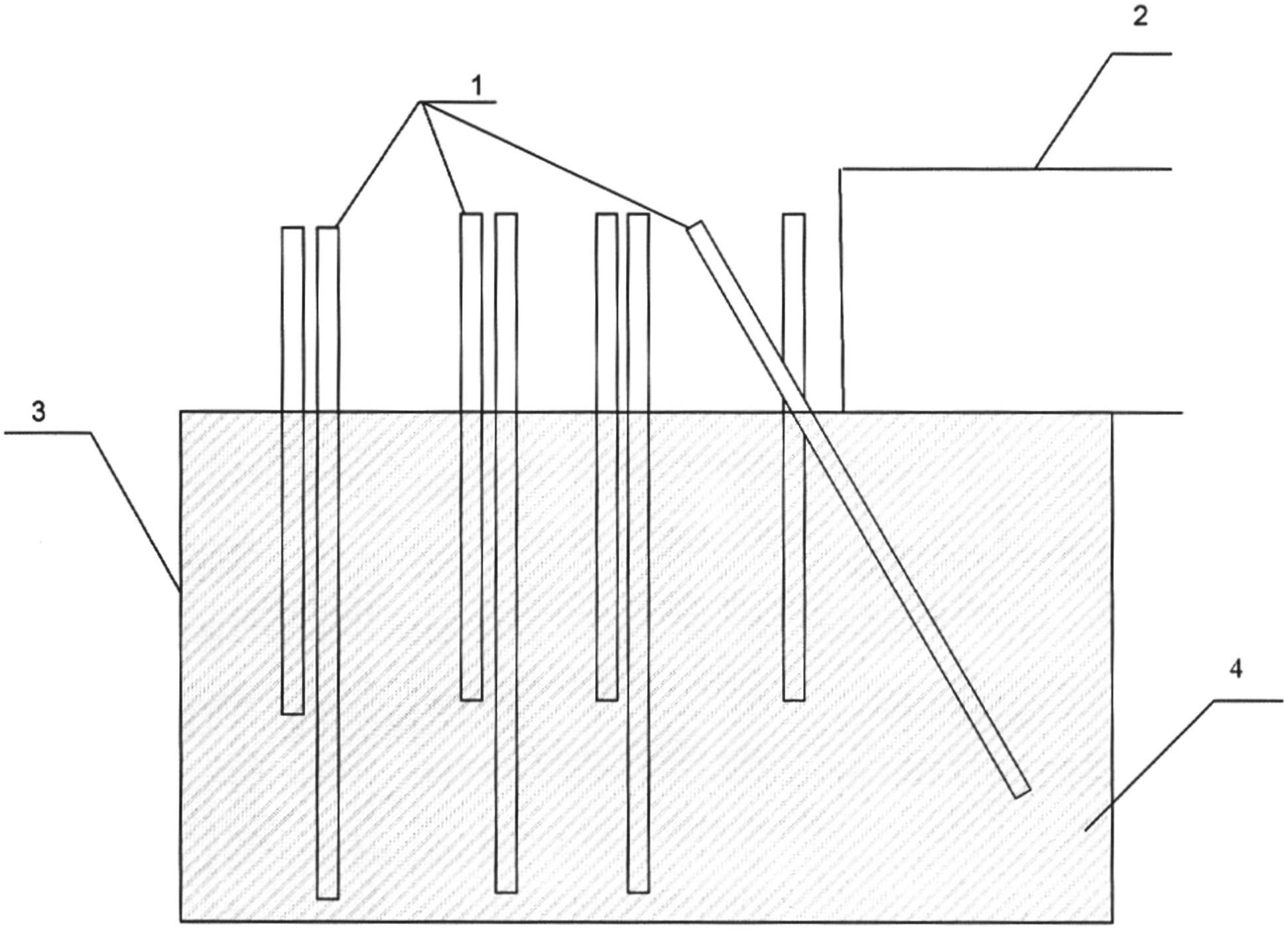
на фиг.1 - схема расположения инъекторов стены в толще земли;figure 1 - arrangement of wall injectors in the thickness of the earth;
на фиг.2 - схема расположения инъекторов, вид сверху.figure 2 - arrangement of injectors, top view.
Армированная грунтоцементная стена содержит металлические неизвлекаемые инъекторы 1. Позицией 2 обозначено защищаемое здание, позицией 3 - борт откапываемого вблизи котлована, позицией 4 - образованный грунтоцементный армированный массив.The reinforced soil-cement wall contains non-removable metal injectors 1. Position 2 denotes the protected building, position 3 denotes the side of the excavated near the foundation pit, position 4 denotes the reinforced cement-reinforced massif.
Сооружение армированной грунтоцементной стены осуществляют следующим образом.The construction of a reinforced soil-cement wall is as follows.
На первом этапе работ проводят разметку сетки под скважины, их бурение и последующую забивку инъекторов 1. Разметка ведется по естественному рельефу, на расстоянии 50-70 см от борта 3 откапываемого котлована. Скважины могут быть пробурены вертикально, наклонно или иметь лучевое расхождение в зависимости от назначения грунтоцементной стены.At the first stage of the work, the grid is marked out for the wells, their drilling and subsequent driving of injectors 1. The marking is carried out according to the natural topography, at a distance of 50-70 cm from the side 3 of the excavated foundation pit. Wells can be drilled vertically, obliquely or have a beam divergence depending on the purpose of the cement wall.
Сначала создают барьерный ряд инъекторов. За барьерным рядом инъекторы 1 забивают в предварительно пробуренные по сетке скважины. Размеры сетки зависят от состава и свойств грунтов. После забивки всех инъекторов 1 производится их обвязка круглым стальным прутком (не показано). Обвязка производится сваркой стального прутка с телом инъектора 1.First create a barrier row of injectors. Behind the barrier row, injectors 1 are driven into pre-drilled wells. The size of the mesh depends on the composition and properties of the soil. After driving all injectors 1, they are strapped with a round steel bar (not shown). The strapping is performed by welding a steel bar with the body of the injector 1.
Затем в инъекторы 1 нагнетают инъекционный цементный раствор. В инъекторы барьерного ряда инъекционный раствор нагнетают в первую очередь, причем в более вязкой консистенции с применением быстротвердеющих добавок, что позволяет создать экран, препятствующий прорыву инъекционного раствора за пределы цементируемой зоны, и дает ощутимую экономию расходных материалов.Then injected cement mortar is injected into the injectors 1. Injection solution is injected into the barrier row injectors first of all, and in a more viscous consistency with the use of quick-hardening additives, which allows you to create a screen that prevents the injection solution from breaking outside the cemented area, and gives tangible savings in consumables.
При установке в одну скважину двух или трех инъекторов, предназначенных для поочередной цементации двух или трех зон по различной глубине расположения, перфорированная часть каждого из них расположена ниже перфорированной части предыдущего, не перекрывая ее. При этом при установке двух инъекторов второй инъектор будет иметь глухую часть, равную перфорированной части первого инъектора, а при установке третьего инъектора высота его глухой части будет складываться из суммы высот перфорированных частей первого и второго инъектора для точного растекания инъекционного раствора по каждой из зон укрепления (цементации) по глубине. Цементацию зон грунта по глубине производят поэтапно - нисходящим или восходящим способом (от более короткого инъектора к более длинному или наоборот).When two or three injectors are installed in one well, intended for alternately cementing two or three zones at different depths, the perforated part of each of them is located below the perforated part of the previous one, without blocking it. In this case, when installing two injectors, the second injector will have a blind part equal to the perforated part of the first injector, and when installing the third injector, the height of its blind part will be the sum of the heights of the perforated parts of the first and second injector for accurate spreading of the injection solution in each of the reinforcement zones ( cementation) in depth. Cementation of soil zones in depth is carried out in stages - downward or ascending (from a shorter injector to a longer one or vice versa).
По площади цементационные работы ведут постепенным сближением, начиная с максимальных расстояний между инъекторами, при которых гидравлическая связь между ними при нагнетании раствора практически отсутствует. В случае усложнения с нагнетанием проектного количества растворов инъекционный раствор подают в зону цементации через каждый инъектор поэтапно, создавая в зоне цементации послойное грунто-цементное соединение. В результате образуется грунтоцементный армированный массив 4.In terms of area, cementing work is carried out by a gradual rapprochement, starting with the maximum distances between the injectors, at which the hydraulic connection between them is practically absent during injection of the solution. In case of complication with the injection of the design quantity of solutions, the injection solution is fed into the cementation zone through each injector in stages, creating a layered soil-cement compound in the cementation zone. As a result, a soil-cement reinforced massif 4 is formed.
Количество рядов устанавливаемых инъекторов не должно быть менее 3-х. Инъекторы в рядах размещаются в шахматном порядке.The number of rows of installed injectors should not be less than 3. Injectors in rows are staggered.
Укрепление грунтов выполняют под пригрузом, создаваемым вышележащими естественными грунтами, телом сооружения или специальной плитой. Вес, деформационные свойства, несущая способность и водопроницаемость пригрузочного слоя должны обеспечивать проведение цементации при проектном давлении раствора без нарушения сплошности пригрузочного слоя и без утечки цементного раствора на поверхность или в пригрузочный слой. Цементацию ведут под рабочим давлением от 5-15 атм.Soil strengthening is carried out under the load created by overlying natural soils, the body of the structure or a special plate. Weight, deformation properties, bearing capacity and permeability of the loading layer should ensure cementation at the design pressure of the mortar without violating the continuity of the loading layer and without leakage of cement mortar to the surface or to the loading layer. Cementation is carried out under a working pressure of 5-15 atm.
По окончании цементационных работ надземную часть инъектора срезают и заливают цементной пробкой.At the end of the cementation work, the aboveground part of the injector is cut off and filled with a cement plug.
Полезная модель поясняется таблицами 1-3, в которых показаны примеры применения заявляемого технического решения на конкретных объектах (3 объекта).The utility model is illustrated in tables 1-3, which show examples of the application of the proposed technical solution for specific objects (3 objects).
Мпаdeformation modulus
MPa
Из таблиц следует, что в результате применения полезной модели в обрабатываемом грунте создается армированная грунтоцементная стена с повышенными физико-механическими свойствами.From the tables it follows that as a result of the application of the utility model in the cultivated soil, a reinforced cement-cement wall is created with enhanced physical and mechanical properties.
Произведенные с использованием полезной модели работы показали, что ни на одном из объектов осадки существующих зданий не было. Борта котлована не осыпались и до окончания строительства имели вид грунтостеклянной поверхности.The work performed using the utility model showed that there was no settlement of existing buildings at any of the objects. The sides of the pit did not crumble and before the end of construction had the appearance of a glass-earth surface.
Производство работ по устройству грунтоцементной армированной стены является экологически чистым, оборудование для производства работ не осуществляет вредных выбросов в атмосферу, так как работает от электрических блоков питания. Производство является почти безотходным.The construction of a soil-cement reinforced wall is environmentally friendly, the equipment for the production of works does not carry out harmful emissions into the atmosphere, since it works from electric power supplies. Production is almost waste-free.
Сооружение грунтоцементной армированной стены возможно практически на всех видах грунтов: скальных и полускальных в основании зданий и сооружений, в том числе в откосах котлованов, закарстованных, несвязных (песок, гравий, галечник), насыпных и просадочных.The construction of a reinforced cement-reinforced wall is possible on almost all types of soils: rocky and semi-rocky at the base of buildings and structures, including in the slopes of foundation pits, karst, incoherent (sand, gravel, gravel), bulk and subsidence.
В результате применения полезной модели создается практически однородное грунтоцементное сооружение (стена) с высокой несущей способностью. Укрепленный грунт представляет собой новый техногенный массив, состоящий из природных грунтов, вкраплений цементного камня, других введенных в грунт компонентов и неизвлекаемых стальных инъекторов, являющихся вертикальными элементами армирования техногенного массива, который совместно с наземным строением образует единую пространственную структуру, обладающую высокой распределительной и несущей способностью. Армированная грунтоцементная стена заменяет дорогостоящие ограждающие сооружения (шпунты из буронабивных свай), что дает ощутимую экономию при строительстве зданий и сооружений.As a result of the application of the utility model, an almost homogeneous cement-cement structure (wall) with high bearing capacity is created. The reinforced soil is a new technogenic massif, consisting of natural soils, inclusions of cement stone, other components introduced into the ground and non-recoverable steel injectors, which are vertical elements of reinforcing the technogenic massif, which together with the ground structure forms a single spatial structure with high distribution and bearing capacity . Reinforced cement-cement wall replaces expensive enclosing structures (tongues from bored piles), which gives tangible savings in the construction of buildings and structures.
Таким образом, применение полезной модели позволяет повысить эффективность защиты зданий и сооружений от откапываемого вблизи котлована, а также удешевить работы.Thus, the application of the utility model allows to increase the efficiency of protecting buildings and structures from being excavated near the foundation pit, as well as reduce the cost of work.
Claims (9)
Priority Applications (1)
| Application Number | Priority Date | Filing Date | Title |
|---|---|---|---|
| RU2012124957/03U RU121275U1 (en) | 2012-06-15 | 2012-06-15 | REINFORCED GROUND-CEMENT WALL FOR PROTECTION OF BUILDINGS AND STRUCTURES FROM THE DIGGED NEAR THE CROWDED |
Applications Claiming Priority (1)
| Application Number | Priority Date | Filing Date | Title |
|---|---|---|---|
| RU2012124957/03U RU121275U1 (en) | 2012-06-15 | 2012-06-15 | REINFORCED GROUND-CEMENT WALL FOR PROTECTION OF BUILDINGS AND STRUCTURES FROM THE DIGGED NEAR THE CROWDED |
Publications (1)
| Publication Number | Publication Date |
|---|---|
| RU121275U1 true RU121275U1 (en) | 2012-10-20 |
Family
ID=47145716
Family Applications (1)
| Application Number | Title | Priority Date | Filing Date |
|---|---|---|---|
| RU2012124957/03U RU121275U1 (en) | 2012-06-15 | 2012-06-15 | REINFORCED GROUND-CEMENT WALL FOR PROTECTION OF BUILDINGS AND STRUCTURES FROM THE DIGGED NEAR THE CROWDED |
Country Status (1)
| Country | Link |
|---|---|
| RU (1) | RU121275U1 (en) |
Cited By (3)
| Publication number | Priority date | Publication date | Assignee | Title |
|---|---|---|---|---|
| RU2685607C1 (en) * | 2018-05-11 | 2019-04-22 | федеральное государственное бюджетное образовательное учреждение высшего образования "Санкт-Петербургский горный университет" | Method for safe undermining of ground objects by an underground structure in complex engineering-geological conditions |
| RU2715784C1 (en) * | 2019-10-03 | 2020-03-03 | Открытое акционерное общество "Научно-исследовательский, проектно-изыскательский институт "Ленметрогипротранс" | Method of correction of subsidence trough at erection of underground structure by closed method in weak soils |
| RU2749003C1 (en) * | 2020-09-22 | 2021-06-02 | Открытое акционерное общество "Научно-исследовательский, проектно-изыскательский институт "Ленметрогипротранс" | Method for reducing settlement of buildings during construction of underground workings under them |
-
2012
- 2012-06-15 RU RU2012124957/03U patent/RU121275U1/en active IP Right Revival
Cited By (3)
| Publication number | Priority date | Publication date | Assignee | Title |
|---|---|---|---|---|
| RU2685607C1 (en) * | 2018-05-11 | 2019-04-22 | федеральное государственное бюджетное образовательное учреждение высшего образования "Санкт-Петербургский горный университет" | Method for safe undermining of ground objects by an underground structure in complex engineering-geological conditions |
| RU2715784C1 (en) * | 2019-10-03 | 2020-03-03 | Открытое акционерное общество "Научно-исследовательский, проектно-изыскательский институт "Ленметрогипротранс" | Method of correction of subsidence trough at erection of underground structure by closed method in weak soils |
| RU2749003C1 (en) * | 2020-09-22 | 2021-06-02 | Открытое акционерное общество "Научно-исследовательский, проектно-изыскательский институт "Ленметрогипротранс" | Method for reducing settlement of buildings during construction of underground workings under them |
Similar Documents
| Publication | Publication Date | Title |
|---|---|---|
| CN107938676B (en) | Pile foundation construction method for penetrating through full-filling karst cave | |
| JP6166264B2 (en) | How to build a retaining wall | |
| CN105525627B (en) | A kind of two-way anchor fixed board retaining wall and its construction method | |
| CN107503257A (en) | One kind is close to mountain high-filled subgrade stabilization and Deformation control structure and construction method | |
| CN105464074B (en) | A kind of artificial digging pile high polymer grouting safeguard structure and its construction method | |
| CN103774674B (en) | A kind of steel pipe underpinned pile and anchor pole deep foundation pit supporting structure and construction method thereof | |
| CN111101540B (en) | Construction method for passing existing electric power tunnel on open cut tunnel | |
| RU2439246C1 (en) | Method of soil reinforcement | |
| CN104746505A (en) | Method for treating miscellaneous fill foundation combing dynamic consolidation and compaction grouting | |
| JP2015183364A (en) | Method for preventing soil structure from sliding at slope surface layer with geocell fixing operation auxiliary means | |
| CN211200426U (en) | Anti-sliding supporting and retaining structure for miniature steel pipe pile retaining wall | |
| RU121275U1 (en) | REINFORCED GROUND-CEMENT WALL FOR PROTECTION OF BUILDINGS AND STRUCTURES FROM THE DIGGED NEAR THE CROWDED | |
| CN113250240A (en) | Combined side slope protection structure and process of layered net type gabion and concrete | |
| CN110939142A (en) | Roadbed structure for side slope | |
| CN103821140B (en) | A kind of construction method of reinforcing soft foundation | |
| CN100396854C (en) | Column-hammer strong-tamper displacing base kit supporting construction method | |
| CN206873466U (en) | One kind is used for footrill flume section safeguard structure | |
| CN102425179A (en) | Structure of reinforced soil sewer supported by bored concrete piles of mini steel tubes | |
| RU121274U1 (en) | ARTIFICIAL REINFORCED BASIS FOR ESTABLISHED OR RECONSTRUCTED BUILDING | |
| CN212316951U (en) | Roadbed structure for side slope | |
| RU131747U1 (en) | ANTI-FILTRATION SCREEN | |
| CN211080248U (en) | Deep foundation pit supporting structure of adjacent road under complex geological condition | |
| CN210507517U (en) | Combined member suitable for retaining wall heightening | |
| CN103821106B (en) | Small-sized fishing port and channel revetment structure | |
| CN104153356B (en) | The constructing device of concrete-pile and construction method thereof |
Legal Events
| Date | Code | Title | Description |
|---|---|---|---|
| MM9K | Utility model has become invalid (non-payment of fees) |
Effective date: 20170616 |
|
| NF9K | Utility model reinstated |
Effective date: 20180910 |