RU120152U1 - WIND ELECTRIC GENERATOR - Google Patents
WIND ELECTRIC GENERATOR Download PDFInfo
- Publication number
- RU120152U1 RU120152U1 RU2012121366/28U RU2012121366U RU120152U1 RU 120152 U1 RU120152 U1 RU 120152U1 RU 2012121366/28 U RU2012121366/28 U RU 2012121366/28U RU 2012121366 U RU2012121366 U RU 2012121366U RU 120152 U1 RU120152 U1 RU 120152U1
- Authority
- RU
- Russia
- Prior art keywords
- wind
- wind turbine
- vertical
- shaft
- consoles
- Prior art date
Links
Classifications
-
- Y—GENERAL TAGGING OF NEW TECHNOLOGICAL DEVELOPMENTS; GENERAL TAGGING OF CROSS-SECTIONAL TECHNOLOGIES SPANNING OVER SEVERAL SECTIONS OF THE IPC; TECHNICAL SUBJECTS COVERED BY FORMER USPC CROSS-REFERENCE ART COLLECTIONS [XRACs] AND DIGESTS
- Y02—TECHNOLOGIES OR APPLICATIONS FOR MITIGATION OR ADAPTATION AGAINST CLIMATE CHANGE
- Y02E—REDUCTION OF GREENHOUSE GAS [GHG] EMISSIONS, RELATED TO ENERGY GENERATION, TRANSMISSION OR DISTRIBUTION
- Y02E10/00—Energy generation through renewable energy sources
- Y02E10/70—Wind energy
- Y02E10/728—Onshore wind turbines
-
- Y—GENERAL TAGGING OF NEW TECHNOLOGICAL DEVELOPMENTS; GENERAL TAGGING OF CROSS-SECTIONAL TECHNOLOGIES SPANNING OVER SEVERAL SECTIONS OF THE IPC; TECHNICAL SUBJECTS COVERED BY FORMER USPC CROSS-REFERENCE ART COLLECTIONS [XRACs] AND DIGESTS
- Y02—TECHNOLOGIES OR APPLICATIONS FOR MITIGATION OR ADAPTATION AGAINST CLIMATE CHANGE
- Y02E—REDUCTION OF GREENHOUSE GAS [GHG] EMISSIONS, RELATED TO ENERGY GENERATION, TRANSMISSION OR DISTRIBUTION
- Y02E10/00—Energy generation through renewable energy sources
- Y02E10/70—Wind energy
- Y02E10/74—Wind turbines with rotation axis perpendicular to the wind direction
Landscapes
- Wind Motors (AREA)
Abstract
1. Ветроэлектрический генератор, состоящий из генерирующего узла, на роторе которого установлена с возможностью вращения ветротурбина с вертикальной осью вращения, на вертикальном валу ветротурбины в его верхней и нижней частях закреплены от 2 до 5 пар консолей, расположенных в вертикальных плоскостях, проходящих через ось вала, на конце каждой пары консолей закреплен ветровоспринимающий элемент в виде вертикальной лопасти, отличающийся тем, что на каждой паре консолей закреплен по крайней мере один дополнительный ветровоспринимающий элемент в виде вертикальной лопасти. ! 2. Ветроэлектрический генератор, отличающийся тем, что над верхним концом вала ветротурбины установлен роторный ветродвигатель Савониуса, имеющий механическую связь с валом через обгонную муфту. 1. Wind power generator, consisting of a generating unit, on the rotor of which a wind turbine with a vertical axis of rotation is installed with the possibility of rotation, on the vertical shaft of the wind turbine in its upper and lower parts, 2 to 5 pairs of consoles are fixed, located in vertical planes passing through the axis of the shaft , at the end of each pair of consoles, a wind-receiving element in the form of a vertical blade is fixed, characterized in that at least one additional wind-receiving element in the form of a vertical blade is fixed on each pair of consoles. ! 2. A wind power generator, characterized in that a Savonius rotary wind turbine is installed above the upper end of the wind turbine shaft, which has a mechanical connection with the shaft through an overrunning clutch.
Description
Полезная модель относится к ветроэнергетике и может быть использована для преобразования кинетической энергии ветра в электрическую энергию.The utility model relates to wind energy and can be used to convert the kinetic energy of the wind into electrical energy.
Известны ветроэлектрические генераторы, состоящие из генерирующего узла, на роторе которого в подшипниковой опоре установлена ветротурбина с вертикальной осью вращения. К вертикальному валу ветротурбины крепятся ветровоспринимающие элементы в виде лопастей, установленных на концах радиальных консолей (см., например, ветроэнергетические установки ВЭУ-1 «Виндэк - Эрга» [http://www.windec2009.narod.ru/VO_komplex.htm], ветротурбины типа ROPATEC Vertical Easy, Simply Vertical, Maxi Vertical и Big Star Vertical, [http://www.ropatec.com/index_n.php?pid=05&lin=3]. Данные устройства отличаются, в основном, количеством консолей (от 2 до 5), размерами и мощностью (от 1 до 20 кВт)Wind power generators are known, consisting of a generating unit, on the rotor of which a wind turbine with a vertical axis of rotation is installed in the bearing support. Wind-receiving elements in the form of blades mounted on the ends of the radial consoles are attached to the vertical shaft of the wind turbine (see, for example, wind turbines VEU-1 “Vindek-Erga” [http://www.windec2009.narod.ru/VO_komplex.htm], wind turbines of the type ROPATEC Vertical Easy, Simply Vertical, Maxi Vertical and Big Star Vertical, [http://www.ropatec.com/index_n.php?pid=05&lin=3]. These devices differ mainly in the number of consoles (from 2 up to 5), dimensions and power (from 1 to 20 kW)
Известен вертикально-осевой ветродвигатель, в котором каждый ветропринимающий элемент выполнен в виде щелевого крыла, содержащего не менее двух параллельных лопастей [Патент РФ 2283968].Known vertical-axis wind turbine, in which each wind receiving element is made in the form of a slotted wing containing at least two parallel blades [RF Patent 2283968].
1. Ветродвигатель, содержащий ветроколесо с вертикальной осью вращения, снабженное не менее чем тремя ветровоспринимающими элементами, скрепленными с радиальными траверсами, закрепленными на вертикальной оси перпендикулярно ей, при этом внешние концы траверс оперты на кольцевую опору, кроме того, ветроколесо установлено с возможностью взаимодействия с генератором электрической энергии, отличающийся тем, что каждый ветровоспринимающий элемент выполнен в виде щелевого крыла, содержащего не менее двух параллельных лопастей, профилю поперечного сечения которых придана серповидная форма, выпуклая в сторону вращения ветроколеса и вогнутая со стороны ветровоспринимающих поверхностей, при этом ширина и длина лопастей щелевого крыла увеличивается от его поверхности, воспринимающей ветер, не менее чем на 5% от размеров соседней наименьшей, причем поперечному сечению наибольшей лопасти каждого щелевого крыла придана каплеобразная форма, для чего радиус кривизны профиля центральной части ее выпуклой поверхности выполнен меньшим, чем у остальных лопастей щелевого крыла.1. A wind turbine containing a wind wheel with a vertical axis of rotation, equipped with at least three wind pickup elements fastened with radial traverses mounted on a vertical axis perpendicular to it, while the outer ends of the traverse are supported on an annular support, in addition, the wind wheel is installed with the possibility of interaction with an electric energy generator, characterized in that each wind pickup element is made in the form of a slotted wing containing at least two parallel blades, a pop profile the cross section of which is given a crescent shape, convex towards the rotation of the wind wheel and concave from the side of wind-receiving surfaces, while the width and length of the slit wing blades increases from its surface that receives the wind by at least 5% of the size of the adjacent smallest, and the cross section is the largest the blades of each slotted wing are given a drop-like shape, for which the radius of curvature of the profile of the central part of its convex surface is made smaller than that of the other blades of the slotted wing.
2. Ветродвигатель по п.1, отличающийся тем, что образующая ветровоспринимающей поверхности наименьшей из лопастей щелевого крыла радиальна и перпендикулярна вертикальной оси вращения.2. The wind turbine according to claim 1, characterized in that the generatrix of the wind-receiving surface of the smallest of the slit wing blades is radial and perpendicular to the vertical axis of rotation.
Недостатком указанного устройства является такое геометрическое расположение параллельных лопастей, при котором они как бы вложены друг в друга. Т.е. та лопасть, вогнутая поверхность которой обращена к ветру и, следовательно, обеспечивающая наибольший вклад во вращательный момент, практически полностью экранирует расположенную (расположенные) позади нее вторую лопасть (группу лопастей). Это снижает активную площадь лопастей ветротурбины.The disadvantage of this device is such a geometric arrangement of parallel blades, in which they are as if embedded in each other. Those. that blade, the concave surface of which is facing the wind and, therefore, providing the greatest contribution to the rotational moment, almost completely screens the second blade (group of blades) located (located) behind it. This reduces the active area of the blades of the wind turbine.
Наиболее близким решением к заявляемому является ветроэлектрический генератор фирмы ROPATEC [http://www.ropatec.com/index_n.php?pid=05&lhr=3], состоящий из генерирующего узла, на роторе которого в подшипниковой опоре установлена ветротурбина с вертикальной осью вращения. К вертикальному валу ветротурбины в его верхней и нижней частях крепятся от 2 до 5 пар перпендикулярно расположенных к нему консолей.The closest solution to the claimed one is a ROPATEC wind generator [http://www.ropatec.com/index_n.php?pid=05&lhr=3], consisting of a generating unit, on the rotor of which a wind turbine with a vertical axis of rotation is installed in the bearing support. To the vertical shaft of the wind turbine in its upper and lower parts are attached from 2 to 5 pairs of consoles perpendicular to it.
На конце каждой пары консолей закреплена одна вертикальная лопасть - ветровоспринимающий элемент.At the end of each pair of consoles, one vertical blade is fixed - a wind-picking element.
Недостатками указанного устройства являются:The disadvantages of this device are:
- относительно низкие коэффициент использования энергии ветра Ср и общий КПД по сравнению с другими ветроагрегатами, например, горизонтально-осевого пропеллерного типа;- relatively low coefficient of utilization of wind energy C p and overall efficiency compared to other wind turbines, for example, horizontal-axis propeller type;
- необходимость в значительном крутящем моменте для так называемого «страгивания» с места ветротурбины по сравнению с горизонтально-осевыми пропеллерными ветроагрегатами, вследствие чего для «раскручивания» турбин типа ROPATEC необходимы значительно большие скорости ветра.- the need for significant torque for the so-called “straggling” from the place of the wind turbine compared to the horizontal-axis propeller wind turbines, as a result of which significantly higher wind speeds are required to “spin” the ROPATEC turbines.
Следствием этого для ветровых турбин ROPATEC является невысокое значение удельной генерируемой электрической мощности, приведенное к единичной сметаемой площади, которая для турбин с вертикальной осью определяется как произведение диаметра ветротурбины на длину лопасти.The consequence of this for ROPATEC wind turbines is the low specific electric power generated, reduced to a unit swept area, which for turbines with a vertical axis is defined as the product of the diameter of the wind turbine and the length of the blade.
Прямая попытка увеличить электрическую мощность указанных выше турбин типа ROPATEC с вертикальной осью вращения обычно сводится к увеличению рабочей площади лопастей таких ветротурбин. Однако, при этом также увеличивается поперечное сечение (парусность) турбины и сила поперечного давления ветра на нее (суммарная аэродинамическая нагрузка на поверхность лопастей, образующаяся в результате поперечного сопротивления профиля лопасти ветровому потоку). При резких порывах ветра в этом случае возникает значительный изгибающий и опрокидывающий момент, что может привести к недопустимым изгибам (поломке) вала, стойки, опоры или несущей мачты ветроэлектрического генератора.A direct attempt to increase the electric power of the above ROPATEC turbines with a vertical axis of rotation usually comes down to increasing the working area of the blades of such wind turbines. However, this also increases the cross section (windage) of the turbine and the force of the transverse wind pressure on it (total aerodynamic load on the surface of the blades, resulting from the transverse resistance of the blade profile to the wind flow). With sudden gusts of wind in this case, a significant bending and tilting moment occurs, which can lead to unacceptable bending (breakage) of the shaft, stand, support or carrier mast of the wind electric generator.
Задачей предложенной полезной модели является увеличение коэффициента использования энергии ветра Ср, удельной выработки электроэнергии на единицу сметаемой площади без увеличения изгибающих и опрокидывающих моментов при боковом направлении ветра на лопасть.The objective of the proposed utility model is to increase the coefficient of utilization of wind energy С p , specific electricity generation per unit of swept area without increasing bending and overturning moments with lateral wind direction to the blade.
Для достижения указанной задачи предложен ветроэлектрический генератор, состоящий из генерирующего узла, на роторе которого установлена с возможностью вращения ветротурбина с вертикальной осью вращения, на вертикальном валу ветротурбины в ее верхней и нижней частях закреплены от 2 до 5 пар консолей, расположенных в вертикальных плоскостях, проходящих через ось вала, на конце каждой пары консолей закреплен ветровоспринимающий элемент в виде вертикальной лопасти, при этом на каждой паре консолей закреплен по крайней мере еще один дополнительный ветровоспринимающий элемент в виде вертикальной лопасти.To achieve this, a wind-driven generator is proposed, consisting of a generating unit, on the rotor of which a wind turbine with a vertical axis of rotation is mounted for rotation, from 2 to 5 pairs of consoles located in vertical planes passing through the vertical shaft of the wind turbine are fixed in its upper and lower parts through the shaft axis, at the end of each pair of consoles, a wind-picking element in the form of a vertical blade is fixed, while at least one additional component is fixed on each pair of consoles Tel'nykh vetrovosprinimayuschy element in the form of vertical vanes.
Кроме того, над верхним концом вала ветротурбины может быть установлен роторный ветродвигатель Савониуса, имеющий механическую связь с валом через обгонную муфту.In addition, above the upper end of the wind turbine shaft, a Savonius rotor wind turbine may be installed, having mechanical connection with the shaft through an overrunning clutch.
Данное указанное многолопастное исполнение ветровоспринимающих элементов ветровой турбины позволяет, во-первых, увеличить полезные аэродинамические характеристики турбины, и, в частности коэффициент Ср, поскольку обеспечивает почти двух- или трехкратное усиление крутящего момента при сохранении фиксированной сметаемой площади. В то же время, предлагаемая полезная модель не вызывает заметного увеличения бокового поперечного сопротивления ветру.This indicated multi-blade design of the wind-receiving elements of the wind turbine allows, firstly, to increase the useful aerodynamic characteristics of the turbine, and, in particular, the coefficient C p , since it provides almost two or three times the torque amplification while maintaining a fixed swept area. At the same time, the proposed utility model does not cause a noticeable increase in lateral lateral resistance to wind.
Во-вторых, еще одним положительным техническим результатом является возможность снизить минимальную скорость ветра, необходимую для «страгивания» турбины, по сравнению с вертикально-осевыми ветротурбинами типа ROPATEC и ВЭУ-1 «Виндек-Эрга».Secondly, another positive technical result is the ability to reduce the minimum wind speed necessary for "straggling" the turbine, compared with vertical-axis wind turbines of the type ROPATEC and VEU-1 Vindek-Erga.
В третьих, многолопастная конфигурация турбины, как известно из практики полетов на самолетах типа биплан, обеспечивает большую, чем у монопланов, устойчивость к срыву потока с крыла, что также способствует увеличению коэффициента Ср.Thirdly, the multi-blade configuration of the turbine, as is known from the practice of flying on a biplane type aircraft, provides greater resistance to stall flow from the wing than monoplanes, which also increases the coefficient C p .
С целью еще более снизить минимальную скорость ветра, необходимую для страгивания турбины, в верхней части основной многолопастной ветротурбины можно поместить дополнительный роторный ветродвигатель Савониуса [http://www.wetroenergetika.ru/14%20savoinus.html], закрепленный сооспо с валом основной турбины и передающий вращение последней через обгонную муфту.In order to further reduce the minimum wind speed necessary for stragging the turbine, an additional Savonius rotor wind turbine [http://www.wetroenergetika.ru/14%20savoinus.html] can be placed in the upper part of the main multi-blade wind turbine, fixed in conjunction with the shaft of the main turbine and transmitting the rotation of the latter through an overrunning clutch.
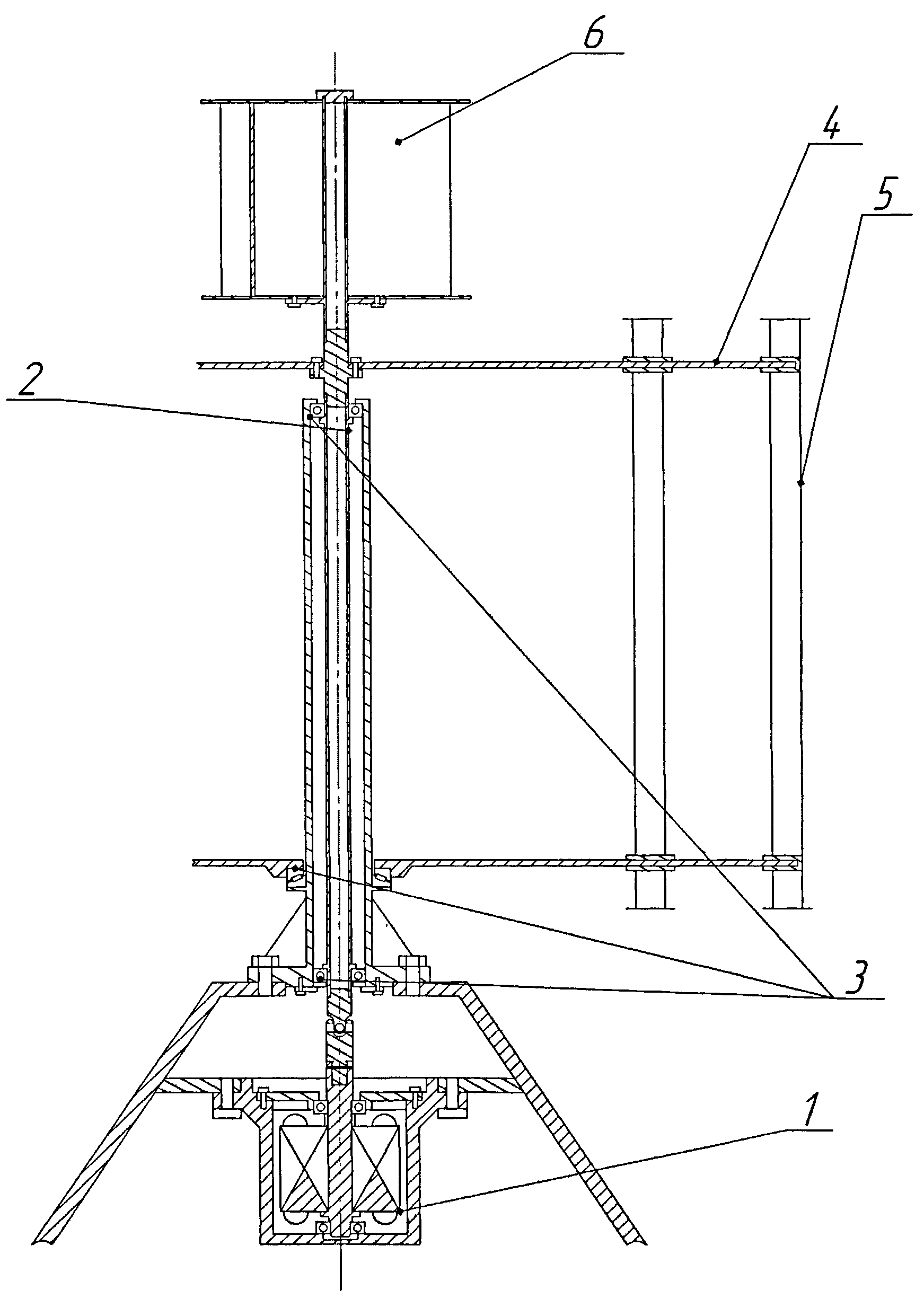
На чертежах схематично представлена предложенная полезная модель.The drawings schematically represent the proposed utility model.
На фиг.1 представлен разрез ветротурбины, снабженной одной дополнительной лопастью на каждой консоли.Figure 1 shows a section of a wind turbine equipped with one additional blade on each console.
На фиг.2 для примера показан вид сверху на трехконсольную ветротурбину, имеющую по одной дополнительной лопасти на каждой паре консолей. Стрелкой показано направления вращения.Figure 2 for example shows a top view of a three-console wind turbine having one additional blade on each pair of consoles. The arrow shows the direction of rotation.
Ветроэлектрический генератор содержит:The wind electric generator contains:
генерирующий узел 1, вертикальный вал ветротурбины 2; установленный в подшипниковых опорах 3. К валу в его верхней и нижней частях крепятся от 2 до 5 пар консолей 4, а на каждой паре консолей расположены по две или более вертикальные лопасти 5. В верхней части может быть установлен дополнительный роторный ветродвигатель Савониуса 6.generating unit 1, vertical shaft of a wind turbine 2; installed in the bearings 3. From 2 to 5 pairs of consoles 4 are attached to the shaft in its upper and lower parts, and two or more vertical blades 5 are located on each pair of consoles 5. An additional Savonius rotor wind turbine 6 can be installed in the upper part.
Ветроэлектрический генератор работает следующим образом.The wind electric generator operates as follows.
Ротор Савониуса 6, как показано многими исследователями (см., например [Saha U.K., Rajkumar M.J., On the performance analysis of Savonius rotor with twisted blades, Renewable Energy 31 (2006) 1776-1788]), имеет относительно высокий коэффициент Ср и приходит в движение при малых скоростях ветра (1-3 м/с). Благодаря этому он через обгонную муфту (на рисунке не показана) даже при слабом ветре приводит во вращение вал ветротурбины 2. Обладая даже небольшой начальной угловой скоростью, ветротурбина при усилении ветра быстрее набирает обороты и, следовательно, раньше начинает вырабатывать электроэнергию и произведет ее больше, чем такая же ветротурбина без начального вращения.The Savonius rotor 6, as shown by many researchers (see, for example, [Saha UK, Rajkumar MJ, On the performance analysis of Savonius rotor with twisted blades, Renewable Energy 31 (2006) 1776-1788]), has a relatively high coefficient C p and comes into motion at low wind speeds (1-3 m / s). Due to this, he drives a wind turbine shaft 2 even with a weak wind through an overrunning clutch (not shown). Having even a small initial angular velocity, the wind turbine picks up speed faster when the wind is amplified and, therefore, starts generating electricity earlier and will produce more. than the same wind turbine without initial rotation.
При скоростях ветра ~5 м/с и выше предлагаемая ветротурбина вращается под действием таких же аэродинамических сил, что и прототип, с тем отличием, что моменты сил, действующие на дополнительные лопасти, суммируются с моментами, действующими на основные, расположенные на концах консолей. Это позволяет увеличить суммарный вращающий момент сил в 1,7-1,9 раза для двухлопастной конструкции, показанной на фиг.1, и в 2,4-2,6 раза для трехлопастной. Точное значение коэффициента увеличения момента сил определяется площадью дополнительных лопастей и их расположением на консоли.At wind speeds of ~ 5 m / s and higher, the proposed wind turbine rotates under the same aerodynamic forces as the prototype, with the difference that the moments of force acting on the additional blades are summed up with the moments acting on the main ones located at the ends of the consoles. This allows you to increase the total torque of the forces of 1.7-1.9 times for the two-blade design shown in figure 1, and 2.4-2.6 times for the three-blade. The exact value of the coefficient of increase in torque is determined by the area of the additional blades and their location on the console.
Механическая мощность, вырабатываемая ветротурбиной, есть произведение угловой скорости вращения на вращающий момент, поэтому наличие дополнительных лопастей позволяет при сохранении сметаемой площади и угловой скорости увеличить полезную мощность пропорционально увеличению момента, т.е. в 1,7-2,6 раза.The mechanical power generated by a wind turbine is the product of the angular velocity of rotation by the torque, therefore, the presence of additional blades allows, while maintaining the swept area and angular velocity, to increase the net power in proportion to the increase in torque, i.e. 1.7-2.6 times.
По мере возрастания угловой скорости ветротурбины ротор Савониуса может перейти в режим, при котором аэродинамические силы, действующие на него, будут создавать тормозящий момент. В этом случае за счет обгонной муфты ротор Савониуса продолжит вращение с меньшей, чем у турбины угловой скоростью, но без снижения полезной мощности ветрогенератора. При ослаблении ветра угловая скорость ротора Савониуса вновь сравняется со скоростью турбины, и он будет поддерживать ее вращение.As the angular velocity of the wind turbine increases, the Savonius rotor can go into a mode in which the aerodynamic forces acting on it will create a braking torque. In this case, due to the overrunning clutch, the Savonius rotor will continue to rotate at an angular speed lower than that of the turbine, but without reducing the useful power of the wind generator. With the weakening of the wind, the angular velocity of the Savonius rotor is again equal to the speed of the turbine, and it will maintain its rotation.
В тоже время поперечное сечение (парусность) турбины и сила поперечного давления ветра на нее (суммарная аэродинамическая нагрузка на поверхность лопастей, образующаяся в результате поперечного сопротивления профиля лопасти ветровому потоку) практически не меняются, т.к. дополнительные лопасти, когда они оказываются расположенными перпендикулярно ветровому потоку, укрыты от него внешней (основной) лопастью. Поэтому предлагаемая конструкция ветротурбины не требует дополнительного усиления механической прочности несущих элементов ветрогенератора..At the same time, the cross section (windage) of the turbine and the force of the transverse wind pressure on it (total aerodynamic load on the surface of the blades resulting from the transverse resistance of the blade profile to the wind flow) practically do not change, because additional blades, when they are located perpendicular to the wind flow, are covered from it by an external (main) blade. Therefore, the proposed design of the wind turbine does not require additional strengthening of the mechanical strength of the bearing elements of the wind generator ..
Таким образом, данное устройство позволит при фиксированных габаритных размерах и сметаемой площади ветровой турбины существенно повысить коэффициент использовании кинетической энергии ветрового потока и, как следствии этого, повысить КПД ветроэлектрического генератора и производимую им электрическую мощность, что достигается за счет применения в данной полезной модели спаренных или строенных лопастей ветровой турбины аналогично тому, как в авиации для увеличения подъемной силы крыла применяют схемы биплана и триплана.Thus, this device will allow for a fixed overall dimensions and a swept area of the wind turbine to significantly increase the utilization of the kinetic energy of the wind flow and, as a consequence, increase the efficiency of the wind electric generator and the electric power it generates, which is achieved through the use of paired or constructed blades of a wind turbine in the same way as in aviation, biplane and triplane schemes are used to increase the wing lift.
Claims (2)
Priority Applications (1)
| Application Number | Priority Date | Filing Date | Title |
|---|---|---|---|
| RU2012121366/28U RU120152U1 (en) | 2012-05-24 | 2012-05-24 | WIND ELECTRIC GENERATOR |
Applications Claiming Priority (1)
| Application Number | Priority Date | Filing Date | Title |
|---|---|---|---|
| RU2012121366/28U RU120152U1 (en) | 2012-05-24 | 2012-05-24 | WIND ELECTRIC GENERATOR |
Publications (1)
| Publication Number | Publication Date |
|---|---|
| RU120152U1 true RU120152U1 (en) | 2012-09-10 |
Family
ID=46939268
Family Applications (1)
| Application Number | Title | Priority Date | Filing Date |
|---|---|---|---|
| RU2012121366/28U RU120152U1 (en) | 2012-05-24 | 2012-05-24 | WIND ELECTRIC GENERATOR |
Country Status (1)
| Country | Link |
|---|---|
| RU (1) | RU120152U1 (en) |
Cited By (2)
| Publication number | Priority date | Publication date | Assignee | Title |
|---|---|---|---|---|
| RU191762U1 (en) * | 2019-06-04 | 2019-08-21 | Владимир Степанович Сухин | WIND POWER INSTALLATION OF ORTHOGONAL TYPE |
| RU2716635C1 (en) * | 2019-06-04 | 2020-03-13 | Владимир Степанович Сухин | Wind-driven power plant of orthogonal type |
-
2012
- 2012-05-24 RU RU2012121366/28U patent/RU120152U1/en active
Cited By (2)
| Publication number | Priority date | Publication date | Assignee | Title |
|---|---|---|---|---|
| RU191762U1 (en) * | 2019-06-04 | 2019-08-21 | Владимир Степанович Сухин | WIND POWER INSTALLATION OF ORTHOGONAL TYPE |
| RU2716635C1 (en) * | 2019-06-04 | 2020-03-13 | Владимир Степанович Сухин | Wind-driven power plant of orthogonal type |
Similar Documents
| Publication | Publication Date | Title |
|---|---|---|
| US7988413B2 (en) | Vertical axis wind turbine | |
| US5405246A (en) | Vertical-axis wind turbine with a twisted blade configuration | |
| EP2314867A2 (en) | Vertical shaft type darius windmill | |
| CN203476602U (en) | Small combined vertical axis wind turbine | |
| US20100158697A1 (en) | Multi-rotor vertical axis wind turbine | |
| WO2010102459A1 (en) | Movable-blade variable-speed type wind turbine | |
| JP2013534592A (en) | Vertical axis windmill | |
| WO2012007934A1 (en) | Dual vertical wind turbine | |
| JP2012092651A (en) | Wind power generation apparatus | |
| RU120152U1 (en) | WIND ELECTRIC GENERATOR | |
| CN203717235U (en) | Multilayer unfolding-wing swinging-blade type vertical shaft wind power generating unit | |
| KR20120139154A (en) | Vertical axis type wind power generator fused lift and drag | |
| RU2283968C1 (en) | Windmill | |
| US8070449B2 (en) | Wind turbine | |
| CN101581278A (en) | Lift force blade system for aerogenerator | |
| CN101886610B (en) | Blade system of vertical axis wind turbine | |
| CN203362390U (en) | Centrifugal variable pitch wind driven generator | |
| WO2013109133A1 (en) | A wind turbine | |
| KR101418674B1 (en) | Louver guided wind turbine | |
| RU122450U1 (en) | WIND ELECTRIC GENERATOR | |
| RU105688U1 (en) | ROTARY WIND POWER INSTALLATION VERTICAL AXLE ROTATION (VARIANTS) | |
| CN221683103U (en) | Space streamline blade tip half long chord variable pitch wind power generation blade | |
| RU2470181C2 (en) | Wind turbine with vertical rotational axis | |
| RU2347941C1 (en) | Propeller-turbine | |
| RU2485345C1 (en) | Modified darrieus turbine |