RU113401U1 - END GRILLE FOR THERMAL FUEL ASSEMBLY OF THE CHANNEL NUCLEAR REACTOR - Google Patents
END GRILLE FOR THERMAL FUEL ASSEMBLY OF THE CHANNEL NUCLEAR REACTOR Download PDFInfo
- Publication number
- RU113401U1 RU113401U1 RU2011143581/07U RU2011143581U RU113401U1 RU 113401 U1 RU113401 U1 RU 113401U1 RU 2011143581/07 U RU2011143581/07 U RU 2011143581/07U RU 2011143581 U RU2011143581 U RU 2011143581U RU 113401 U1 RU113401 U1 RU 113401U1
- Authority
- RU
- Russia
- Prior art keywords
- holes
- round
- nuclear reactor
- fuel
- fuel assembly
- Prior art date
Links
Classifications
-
- Y—GENERAL TAGGING OF NEW TECHNOLOGICAL DEVELOPMENTS; GENERAL TAGGING OF CROSS-SECTIONAL TECHNOLOGIES SPANNING OVER SEVERAL SECTIONS OF THE IPC; TECHNICAL SUBJECTS COVERED BY FORMER USPC CROSS-REFERENCE ART COLLECTIONS [XRACs] AND DIGESTS
- Y02—TECHNOLOGIES OR APPLICATIONS FOR MITIGATION OR ADAPTATION AGAINST CLIMATE CHANGE
- Y02E—REDUCTION OF GREENHOUSE GAS [GHG] EMISSIONS, RELATED TO ENERGY GENERATION, TRANSMISSION OR DISTRIBUTION
- Y02E30/00—Energy generation of nuclear origin
- Y02E30/30—Nuclear fission reactors
Landscapes
- Structure Of Emergency Protection For Nuclear Reactors (AREA)
Abstract
Концевая решетка тепловыделяющей сборки ядерного реактора, выполненная в виде круглой плиты с круглым отверстием под центральную трубу, круглыми отверстиями под наконечники твэлов, центры которых расположены на концентричных окружностях, и с проливными отверстиями между ними, отличающаяся тем, что проливные отверстия образованы пересечением перемычек, направленных от периферии в направлении к отверстию под центральную трубу, и соседних с ними параллельных им перемычек с перпендикулярными к ним перемычками и с перемычками, ограничивающими круглые отверстия. The end lattice of the fuel assembly of a nuclear reactor, made in the form of a round plate with a round hole for the central pipe, round holes for the tips of the fuel rods, the centers of which are located on concentric circles, and with pouring holes between them, characterized in that the pouring holes are formed by the intersection of the bridges directed from the periphery towards the hole for the central pipe, and adjacent bridges parallel to them with bridges perpendicular to them and with bridges limiting round holes.
Description
Полезная модель относится к атомной энергетике, а именно к элементам тепловыделяющих сборок (ТВС), и может быть использована в реакторах большой мощности канальных (РБМК).The utility model relates to nuclear energy, namely to the elements of fuel assemblies (FA), and can be used in high-power channel reactors (RBMK).
Известна конструкция ТВС ядерного реактора РБМК-1000, содержащая два пучка, состоящих из 18 твэлов каждый, расположенных кольцеобразно по двум концентричным окружностям, закрепленных в концевой опорной решетке и соединенных между собой дистанционирующими решетками (ДР), закрепленными на центральной трубе. Пучки соединены между собой стержнем, проходящим через центральные трубы и хвостовик с помощью резьбового соединения (см. Кириллов П.Л. и др. Справочник по теплогидравлическим расчетам (ядерные реакторы, теплообменники, парогенераторы). М.: Энергоатомиздат, 1984., рис.П.8.11. с.265).The known design of the fuel assemblies of the RBMK-1000 nuclear reactor, containing two beams consisting of 18 fuel elements each arranged annularly along two concentric circles fixed in an end support grid and interconnected by spacer grids (DR), mounted on a central tube. The bundles are interconnected by a rod passing through the central pipes and the shank using a threaded connection (see Kirillov P.L. et al. Handbook of Thermohydraulic Calculations (nuclear reactors, heat exchangers, steam generators). M: Energoatomizdat, 1984., Fig. P. 8.11. P. 265).
Недостатком данной конструкции является возможность проникновения в пучок твэлов посторонних дебриз-предметов достаточно большого размера и повреждение ими оболочек твэлов, что приводит к преждевременной разгерметизации твэлов и выходу из строя ТВС.The disadvantage of this design is the possibility of penetration into the beam bundle of foreign debris objects of a sufficiently large size and damage to the cladding of the fuel rods, which leads to premature depressurization of the fuel rods and failure of the fuel assemblies.
В штатной концевой решетке проливные отверстия имеют вписанный диаметр до 10 мм, а описанный диаметр достигает 15 мм. В связи с этим она пропускает в пучок твэлов дебриз-предметы большого размера (металлическая стружка, стержни и т.п.).In the standard end grid, the pouring holes have an inscribed diameter of up to 10 mm, and the described diameter reaches 15 mm. In this regard, it passes large debris objects (metal shavings, rods, etc.) into the bundle of fuel elements.
Неоднократные послереакторные исследования поврежденных ТВС РБМК-1000 показали, что основной причиной разгерметизации твэлов являются дебриз-повреждения.Repeated post-reactor studies of damaged fuel assemblies RBMK-1000 have shown that debris damage is the main cause of depressurization of fuel elements.
Было предложено оснастить ТВС РБМК дополнительно фильтром, улавливающим дебриз-частицы (антидебризный фильтр АДФ), и установить его в хвостовике ТВС с дистанционатором на входе в ТВС теплоносителя АДФ имеет пазы шириной до 2 мм и перемычки толщиной до 0,8 мм (см. патент РФ 2338272, опубл. 10.11.2008).It was proposed to equip the RBMK fuel assemblies with an additional filter capturing debris particles (ADF anti-debris filter), and install it in the shank of the fuel assembly with a spacer at the inlet of the ADF coolant; it has grooves up to 2 mm wide and jumpers up to 0.8 mm thick (see patent RF 2338272, publ. 10.11.2008).
Недостатком такого технических решений является наличие дополнительного элемента конструкции - фильтра, что увеличивает трудоемкость изготовления и гидравлическое сопротивление ТВС РБМК.The disadvantage of such technical solutions is the presence of an additional structural element - a filter, which increases the complexity of manufacturing and hydraulic resistance of RBMK fuel assemblies.
Наиболее близкой к предлагаемой конструкции концевой решетки является опорная концевая решетка тепловыделяющей сборки ядерного реактора, выполненная в виде плиты с круглыми отверстиями под наконечники твэлов и проливными отверстиями между ними, каждое из которых образовано тремя дугами радиуса R (см. патент РФ №94043, опубл. 10.05.2010).Closest to the proposed design of the end grating is the supporting end grating of the fuel assembly of the nuclear reactor, made in the form of a plate with round holes for the tips of the fuel rods and pouring holes between them, each of which is formed by three arcs of radius R (see RF patent No. 94043, publ. 05/10/2010).
Недостатком данной конструкции является возможность проникновения в пучок твэлов посторонних дебриз-предметов достаточно большого размера и повреждение ими оболочек твэлов, что приводит к преждевременной разгерметизации твэлов и выходу из строя ТВС.The disadvantage of this design is the possibility of penetration into the beam bundle of foreign debris objects of a sufficiently large size and damage to the cladding of the fuel rods, which leads to premature depressurization of the fuel rods and failure of the fuel assemblies.
Задачей полезной модели является устранение дебриз - повреждений твэлов.The objective of the utility model is to eliminate debris - damage to fuel rods.
Технический результат полезной модели заключается в исключении проникновения дебриз-предметов через опорную решетку без использования дополнительной фильтрующей решетки. Для устранения этого недостатка предлагается изменить конфигурацию проливных отверстий концевой решетки с целью придания им свойства фильтрующего элемента.The technical result of the utility model is to prevent penetration of debris objects through the support grid without the use of an additional filter grate. To eliminate this drawback, it is proposed to change the configuration of the pouring holes of the end grating in order to give them the properties of a filter element.
Технический результат достигается за счет того, что в концевой решетке тепловыделяющей сборки ядерного реактора, выполненной в виде круглой плиты с круглым отверстием под центральную трубу и круглыми отверстиями под наконечники твэлов, центры которых расположены на концентричных окружностях, и с проливными отверстиями между ними, согласно предложению проливные отверстия образованы пересечением перемычек, направленных от периферии в направлении к отверстию под центральную трубу, и соседних с ними параллельных перемычек с перпендикулярными к ним перемычками и с перемычками, ограничивающими круглые отверстия.The technical result is achieved due to the fact that in the end lattice of the fuel assembly of a nuclear reactor, made in the form of a round plate with a round hole for the central pipe and round holes for the tips of the fuel rods, the centers of which are located on concentric circles, and with pouring holes between them, according to the proposal pouring holes are formed by the intersection of jumpers directed from the periphery towards the hole under the central pipe, and adjacent parallel jumpers with perpendiculars striking jumper to them and with jumpers bounding the round holes.
Сущность полезной модели поясняется чертежом.The essence of the utility model is illustrated in the drawing.
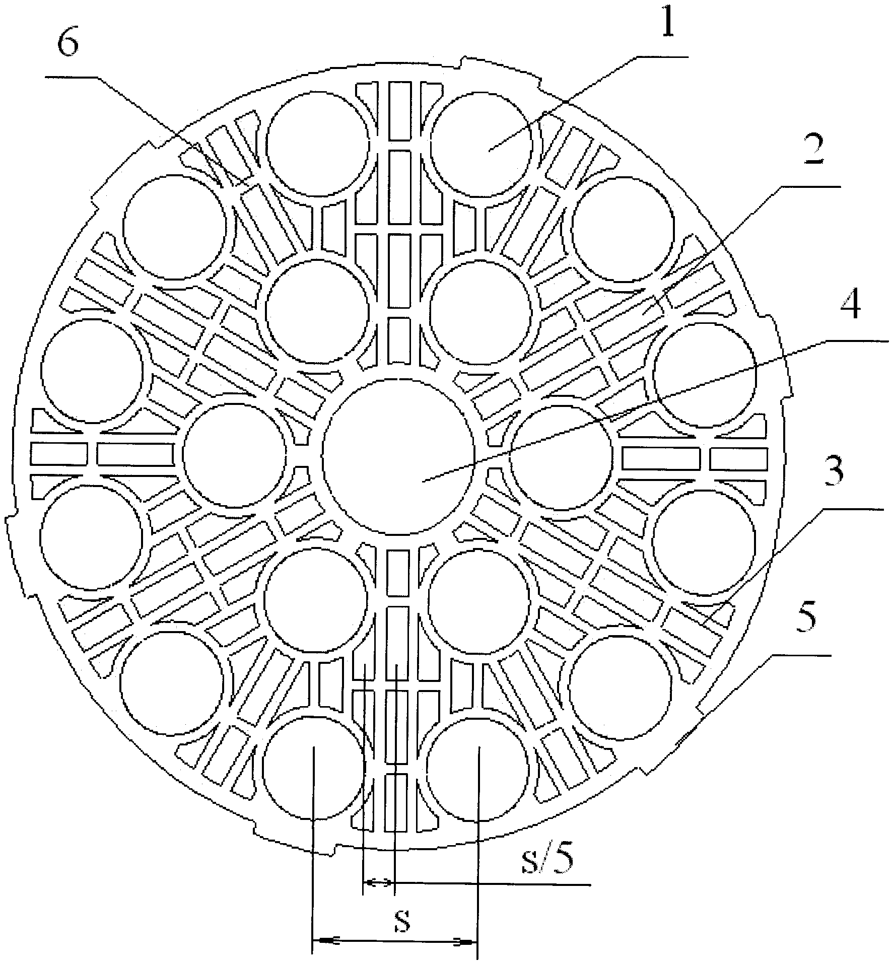
На фиг.1 схематично изображена опорная решетка предлагаемой тепловыделяющей сборки канального ядерного реактора.Figure 1 schematically shows the support grid of the proposed fuel Assembly of the channel nuclear reactor.
Предлагаемая опорная решетка (фиг.1) тепловыделяющей сборки канального ядерного реактора имеет круглый наружный обод и содержит центральное круглое отверстие 4 под центральную трубу, круглые отверстия 1 для наконечников твэлов, расположенные кольцеобразно по двум концентричным окружностям. Между круглыми отверстиями 1 и 4 размещены проливные отверстия 2, имеющие вытянутую в направлении от периферии к центральному отверстию 4 форму. Проливные отверстия образованы пересечением перпендикулярных друг другу перемычек 3, направленных от периферии к центральному отверстию 4, и параллельных им соседних более коротких перемычек с перпендикулярными им перемычками 6, а также с перемычками, ограничивающими круглые отверстия 1 и 4. Выступы 5 на наружном ободе решетки служат для центрирования ТВ С в канальной трубе.The proposed support lattice (figure 1) of the fuel assembly of a channel nuclear reactor has a round outer rim and contains a central round hole 4 for the central pipe, round holes 1 for the tips of the fuel rods, located annularly in two concentric circles. Between the circular openings 1 and 4, pouring openings 2 are arranged having a shape elongated in the direction from the periphery to the central opening 4. Pouring holes are formed by the intersection of bridges 3 perpendicular to each other, directed from the periphery to the central hole 4, and adjacent shorter bridges parallel to them with bridges 6 perpendicular to them, and also with bridges that limit round holes 1 and 4. The protrusions 5 on the outer rim of the grill serve to center TV C in the duct pipe.
Материал опорной решетки-фильтра сталь типа Х18Н9Т.The material of the filter support grid is steel type X18H9T.
Предлагается выполнить проливные отверстия опорной решетки вытянутыми в радиальном направлении и образованными пересечением перпендикулярных друг другу перемычек. Проливные отверстия предлагается выполнить шириной 2,1...2,3 мм и для обеспечения наилучших фильтрующих свойств расположить их равномерно между твэлами на расстоянии (с шагом) ~s/5 в окружном направлении, где s - шаг расположения твэлов РБМК во внутреннем кольце, что существенно уменьшит вероятность попадания в пучок твэлов дебриз-предметов и повысит тем самым работоспособность ТВС РБМК.It is proposed to make the pouring holes of the support lattice elongated in the radial direction and formed by the intersection of jumpers perpendicular to each other. It is proposed to fill the holes with a width of 2.1 ... 2.3 mm and to ensure the best filtering properties, place them evenly between the fuel rods at a distance (in steps) ~ s / 5 in the circumferential direction, where s is the pitch of the RBMK fuel rods in the inner ring , which will significantly reduce the likelihood of debris items falling into the fuel bundle and thereby increase the performance of RBMK fuel assemblies.
При этом трудоемкость изготовления опорной решетки существенно не изменится, а отказ от дополнительного фильтрующего элемента дает существенный экономический эффект.At the same time, the complexity of manufacturing the support grid will not change significantly, and the rejection of an additional filter element gives a significant economic effect.
Проведенные расчеты с использованием программного комплекса ANSYS показали, что предлагаемая опорная решетка имеет существенно большую механическую прочность по сравнению со штатной при сохранении проливного сечения.The calculations using the ANSYS software package showed that the proposed support lattice has a significantly higher mechanical strength compared to the standard one while maintaining the cross section.
Claims (1)
Priority Applications (1)
| Application Number | Priority Date | Filing Date | Title |
|---|---|---|---|
| RU2011143581/07U RU113401U1 (en) | 2011-10-28 | 2011-10-28 | END GRILLE FOR THERMAL FUEL ASSEMBLY OF THE CHANNEL NUCLEAR REACTOR |
Applications Claiming Priority (1)
| Application Number | Priority Date | Filing Date | Title |
|---|---|---|---|
| RU2011143581/07U RU113401U1 (en) | 2011-10-28 | 2011-10-28 | END GRILLE FOR THERMAL FUEL ASSEMBLY OF THE CHANNEL NUCLEAR REACTOR |
Publications (1)
| Publication Number | Publication Date |
|---|---|
| RU113401U1 true RU113401U1 (en) | 2012-02-10 |
Family
ID=45854120
Family Applications (1)
| Application Number | Title | Priority Date | Filing Date |
|---|---|---|---|
| RU2011143581/07U RU113401U1 (en) | 2011-10-28 | 2011-10-28 | END GRILLE FOR THERMAL FUEL ASSEMBLY OF THE CHANNEL NUCLEAR REACTOR |
Country Status (1)
| Country | Link |
|---|---|
| RU (1) | RU113401U1 (en) |
Cited By (1)
| Publication number | Priority date | Publication date | Assignee | Title |
|---|---|---|---|---|
| RU168720U1 (en) * | 2016-04-07 | 2017-02-17 | Акционерное общество "Ордена Трудового Красного Знамени и ордена труда ЧССР опытное конструкторское бюро "ГИДРОПРЕСС" (АО ОКБ "ГИДРОПРЕСС") | REMOTE LATTICE |
-
2011
- 2011-10-28 RU RU2011143581/07U patent/RU113401U1/en active
Cited By (1)
| Publication number | Priority date | Publication date | Assignee | Title |
|---|---|---|---|---|
| RU168720U1 (en) * | 2016-04-07 | 2017-02-17 | Акционерное общество "Ордена Трудового Красного Знамени и ордена труда ЧССР опытное конструкторское бюро "ГИДРОПРЕСС" (АО ОКБ "ГИДРОПРЕСС") | REMOTE LATTICE |
Similar Documents
| Publication | Publication Date | Title |
|---|---|---|
| JP4294477B2 (en) | Lower nozzle for small debris filtration for nuclear reactor fuel assemblies | |
| RU2742042C1 (en) | Nuclear reactor fuel assembly | |
| CN102365686B (en) | Nuclear fuel assembly with pivot dimpled grids | |
| KR20190121858A (en) | Nuclear Fuel Debris Filtration Lower Nozzle | |
| RU2473989C1 (en) | Nuclear reactor fuel assembly | |
| US20130272479A1 (en) | Lower end fitting for nuclear fuel assembly made from intersecting metal strips | |
| RU113401U1 (en) | END GRILLE FOR THERMAL FUEL ASSEMBLY OF THE CHANNEL NUCLEAR REACTOR | |
| KR101002719B1 (en) | Spacer grid spring having a hole in the contact area with fuel rod | |
| RU2447518C1 (en) | Support grid-filter for fuel assembly of nuclear reactor | |
| CN107767969A (en) | The core structure and core loading method of pressure vessel | |
| RU2610716C1 (en) | Filter for nuclear reactor fuel assembly | |
| RU2728894C1 (en) | Nuclear reactor fuel assembly (versions) | |
| RU2557254C1 (en) | Nuclear reactor fuel assembly spacer grid | |
| RU2610913C1 (en) | Nuclear reactor fuel assembly | |
| RU113402U1 (en) | FILTER CARRIER FOR FUEL ASSEMBLY OF THE NUCLEAR REACTOR | |
| CN109935363B (en) | Fuel assembly and bottom device thereof and bottom tube seat applied to bottom device | |
| KR101474548B1 (en) | Nuclear fuel assembly having a protective grid to prevent flow-induced vibration | |
| KR20200089347A (en) | A bottom nozzle of Nuclear Fuel Assembly formed flow hole by utilizing a layered Aircraft Airfoil Structure | |
| RU2477537C1 (en) | Fuel assembly of nuclear reactor | |
| US9171647B2 (en) | Spacer grid for nuclear fuel assembly for reducing flow-induced vibration | |
| JP5823605B2 (en) | Lower nozzle for use with nuclear fuel assemblies | |
| RU94043U1 (en) | SUPPORT GRILLE FOR FUEL ASSEMBLY OF THE NUCLEAR REACTOR | |
| EA201700569A1 (en) | THERMAL DETECTIVE ASSEMBLY OF A NUCLEAR REACTOR | |
| RU113055U1 (en) | REMOTE LATTICE OF THE HEAT FUEL ASSEMBLY OF A HIGH-ENERGY NUCLEAR REACTOR | |
| US20140037041A1 (en) | Spacer grid for nuclear fuel assembly for reducing high frequency vibration |