RU110715U1 - SPEED COMBINED HELICOPTER - Google Patents
SPEED COMBINED HELICOPTER Download PDFInfo
- Publication number
- RU110715U1 RU110715U1 RU2011130443/11U RU2011130443U RU110715U1 RU 110715 U1 RU110715 U1 RU 110715U1 RU 2011130443/11 U RU2011130443/11 U RU 2011130443/11U RU 2011130443 U RU2011130443 U RU 2011130443U RU 110715 U1 RU110715 U1 RU 110715U1
- Authority
- RU
- Russia
- Prior art keywords
- engines
- helicopter
- wing
- power plant
- rotor
- Prior art date
Links
Abstract
Скоростной комбинированный вертолет, содержащий фюзеляж с крылом и хвостовой балкой, несущий и рулевой винты, силовую установку, топливную систему и систему управления силовой установкой, отличающийся тем, что он содержит установленные на консолях крыла левый и правый двигатели с воздушными винтами или левый и правый реактивные, турбореактивные или турбовентиляторные двигатели, причем каждый двигатель подсоединен к топливной системе и к системе управления силовой установкой, при этом консоли крыла вместе с двигателями на них установлены относительно фюзеляжа с помощью поворотно-разъемных узлов с возможностью демонтажа консолей или их поворота на стоянке, а также с возможностью поворота и аварийного сброса в полете. A high-speed combined helicopter containing a fuselage with a wing and a tail boom, a rotor and a tail rotor, a power plant, a fuel system and a power plant control system, characterized in that it contains left and right propeller engines on the wing consoles or left and right jet engines turbojet or turbofan engines, each engine being connected to the fuel system and to the control system of the power plant, while the wing consoles together with the engines installed on them us relative to the fuselage via a swing-separable assemblies removably consoles or rotation stationary, and rotatably and disaster relief in flight.
Description
Полезная модель относится к винтокрылым летательным аппаратам, а именно к скоростным комбинированным вертолетам.The utility model relates to rotary-wing aircraft, namely to high-speed combined helicopters.
Известен комбинированный летательный аппарат V/STOL (патент US 3666209, публ. 30.05.1972) - самолет вертикального или короткого взлета и посадки с поворотными тяговыми винтами. Он включает фюзеляж с хвостовой частью, крылья, передние участки которых разделены на переднюю и заднюю части, реактивные двигатели, расположенные внутри фюзеляжа и воздушные винты с редукторным приводом, установленные на передней части крыльев, причем передние части крыльев установлены с возможностью поворота вместе с воздушными винтами до 90°.Known combined aircraft V / STOL (patent US 3666209, publ. 05/30/1972) - an airplane of vertical or short take-off and landing with rotary traction propellers. It includes a fuselage with a tail, wings, the front sections of which are divided into front and rear, jet engines located inside the fuselage and propellers with gear drive mounted on the front of the wings, and the front parts of the wings are mounted to rotate together with the propellers up to 90 °.
Известны скоростные комбинированные вертолеты, использующие дополнительные воздушные винты для повышения крейсерской скорости вертолета, которые приводит единая с несущим винтом силовая установка:Known high-speed combined helicopters using additional propellers to increase the cruising speed of the helicopter, which leads a single power plant with a rotor:
Заявка WO 2005/005250, 2005 «Гибридный вертолет», В64С и Заявка WO 2008/145868, 2008 (US №2009/0321554, 2009) «Скоростной гибридный вертолет с большой дальностью полета» В64С 27/22.Application WO 2005/005250, 2005 “Hybrid Helicopter”, B64C and Application WO 2008/145868, 2008 (US No. 2009/0321554, 2009) “High-speed hybrid helicopter with a long flight range” B64C 27/22.
Гибридный вертолет по заявке WO 2008/145868 имеет фюзеляж с расположенными на нем крыльями, тяговые воздушные винты (пропеллеры), установленные на крыльях, несущий винт, хвостовое оперение, силовую установку. Силовая установка с хотя бы одним турбовальным двигателем приводит во вращение несущий винт и пропеллеры и связана как с управлением общим шагом несущего винта, так и с управлением общим шагом воздушного винта на крыле. Фюзеляж снабжен стабилизирующими поверхностями в хвостовой части. Компенсация крутящего момента несущего винта осуществляется изменением тяги пропеллеров и аэродинамическими рулями хвостового оперения.Hybrid helicopter according to the application WO 2008/145868 has a fuselage with wings located on it, traction propellers (propellers) mounted on the wings, main rotor, tail unit, power plant. A power plant with at least one turboshaft engine rotates the main rotor and propellers and is associated with both controlling the common pitch of the main rotor and controlling the common pitch of the rotor on the wing. The fuselage is equipped with stabilizing surfaces in the rear. Compensation of the rotor torque is carried out by changing the propeller thrust and the tail rudders.
Недостатком устройства является постоянная механическая связь несущего винта и воздушных винтов, установленных на крыльях, с силовой установкой (невозможность использования вертолета с неработающими пропеллерами, без использования скоростного режима полета), что приводит к повышенному расходу топлива.The disadvantage of this device is the constant mechanical connection of the rotor and propellers mounted on the wings with the power plant (the inability to use a helicopter with idle propellers without using a high-speed flight mode), which leads to increased fuel consumption.
Наиболее близким аналогом заявляемому техническому решению является комбинированный вертолет по заявке WO 2005/005250. Вертолет представляет собой гибридную комбинацию вертолета и самолета. Модифицированный вертолет имеет несущий винт, хвостовой винт и установленный на носу тянущий воздушный винт (пропеллер), приводимый от единой силовой установки с несущим винтом. Крылья большого удлинения с большими закрылками дополняют конструкцию, обеспечивая подъемную силу при горизонтальном полете. Закрылки используют для снижения сопротивления при вертикальной обдувке (струей от несущего винта) во время вертикального полета и на режиме висения.The closest analogue to the claimed technical solution is a combined helicopter according to the application WO 2005/005250. A helicopter is a hybrid combination of a helicopter and an airplane. The modified helicopter has a rotor, a tail rotor and a pulling propeller mounted on the nose, driven from a single power unit with a rotor. Large elongation wings with large flaps complement the design, providing lift in horizontal flight. Flaps are used to reduce resistance during vertical blowing (by a jet from the rotor) during vertical flight and in hover mode.
Благодаря наличию дополнительного движителя в виде тянущего воздушного винта и крыльев нагрузка на лопасти несущего винта во время поступательного полета уменьшается. Это позволяет увеличить скорость полета, поскольку снимаются ограничения по скорости полета, предъявляемые к обычным вертолетам, связанные с явлением срыва потока на отступающей лопасти, и по максимальным окружным скоростям законцовок лопастей несущего винта. При этом повышается эффективность крыльев и, следовательно, уменьшается нагрузка на несущий винт.Due to the presence of an additional propulsion device in the form of a pulling propeller and wings, the load on the rotor blades during a translational flight is reduced. This allows you to increase the flight speed, since the restrictions on the flight speed imposed on conventional helicopters associated with the phenomenon of stalling the flow on the retreating blade and at the maximum peripheral speeds of the tips of the rotor blades are removed. This increases the efficiency of the wings and, therefore, reduces the load on the rotor.
К недостаткам комбинированного вертолета-аналога можно отнести повышенный расход топлива, связанный с работой носового тянущего винта на всех режимах полета, а также низкую эксплуатационную надежность, связанную с работой одной силовой установки на несущий винт, рулевой хвостовой винт и на носовой тянущий винт, и связанное с этим снижение безопасности.The disadvantages of the combined analog helicopter include increased fuel consumption associated with the operation of the nose pulling propeller in all flight modes, as well as low operational reliability associated with the operation of one power plant on the main rotor, tail rotor and on the nose pulling propeller, and associated with this reduced security.
Задачей заявляемой полезной модели является расширение функциональных возможностей скоростного комбинированного вертолета, повышение безопасности полета и снижение расхода топлива за счет обеспечения возможности независимой работы несущего и тяговых винтов и обеспечения возможности работы вертолета как в скоростном, так и в обычном режиме полета.The objective of the claimed utility model is to expand the functionality of a high-speed combined helicopter, increase flight safety and reduce fuel consumption by enabling independent operation of the main and traction propellers and ensuring the helicopter can operate both in high-speed and in normal flight mode.
Поставленная задача решена за счет того, что скоростной комбинированный вертолет, содержащий фюзеляж с крылом и хвостовой балкой, несущий и рулевой винты, силовую установку, топливную систему и систему управления силовой установкой, в соответствии с заявляемым техническим решением - содержит установленные на консолях крыла левый и правый двигатели с воздушными винтами или левый и правый реактивные, турбореактивные или турбовентиляторные двигатели, причем каждый двигатель подсоединен к топливной системе и к системе управления силовой установкой, при этом консоли крыла вместе с двигателями на них установлены относительно фюзеляжа с помощью поворотно-разъемных узлов с возможностью демонтажа консолей или их поворота на стоянке, а также с возможностью поворота и аварийного сброса в полете.The problem is solved due to the fact that the high-speed combined helicopter containing the fuselage with the wing and tail boom, the main and tail rotors, the power plant, the fuel system and the power plant control system, in accordance with the claimed technical solution, contains the left and right propeller engines or left and right jet, turbojet or turbofan engines, each engine being connected to the fuel system and to the power control system Settings, wherein the wing console with engines installed on them relative to the fuselage via a swing-separable assemblies removably consoles or rotation stationary, and rotatably and disaster relief in flight.
Отсутствие кинематической связи двигателей, установленных на крыле, с силовой установкой несущего винта позволяет расширить функциональные возможности комбинированного вертолета. В зависимости от полетного задания на стоянке снимают консоли крыла (вместе с двигателями на них) или устанавливают их для обеспечения скоростного режима. При этом, соответственно, системы двигателей отключают или подключают к топливной системе, системе управления и бортовым системам скоростного комбинированного вертолета.The lack of kinematic connection of the engines mounted on the wing with the main rotor propulsion system allows expanding the functionality of the combined helicopter. Depending on the flight mission in the parking lot, they remove the wing consoles (together with the engines on them) or install them to ensure high-speed operation. In this case, respectively, engine systems are disconnected or connected to the fuel system, control system and on-board systems of a high-speed combined helicopter.
При демонтаже консолей крыла с двигателями (в случае не использования скоростного режима вертолета) при полетах вертолета снижается расход топлива из-за отсутствия лобового сопротивления тягового двигателя.When dismantling the wing consoles with engines (in the case of not using the high-speed mode of the helicopter) during helicopter flights, fuel consumption is reduced due to the lack of drag of the traction engine.
В случае использования скоростного режима вертолета, запуск двигателей, установленных на крыле, осуществляется экипажем в полете при необходимости значительно увеличить скорость горизонтального полета. Такая возможность также позволяет снизить расход топлива, так как при малых скоростях полета (не в скоростном режиме) тяговые двигатели не потребляют топлива.In the case of using the high-speed mode of the helicopter, the launch of engines mounted on the wing is carried out by the crew in flight, if necessary, significantly increase the speed of horizontal flight. This feature also allows you to reduce fuel consumption, because at low flight speeds (not in high-speed mode), traction engines do not consume fuel.
Аварийный сброс правого и левого двигателей осуществляют при отказе одного из них либо при аварийной посадке, для уменьшения полетного веса вертолета.An emergency reset of the right and left engines is carried out in case of failure of one of them or during an emergency landing, in order to reduce the flight weight of the helicopter.
При отказах силовой установки несущего винта кинематически независимые тяговые движители создают горизонтальную тягу и обеспечивают создание подъемной силы на крыльях комбинированного вертолета. Благодаря этому комбинированный вертолет разгоняют до начала авторотации несущего винта или осуществляют посадку по-самолетному. Управление вертолетом по курсу в этом режиме может осуществляться изменением тяги левого или правого двигателя.In the event of a rotor propulsion system failure, kinematically independent traction propulsors create horizontal traction and provide lift on the wings of the combined helicopter. Due to this, the combined helicopter is dispersed before the start of the rotor autorotation or landing by plane. The control of the helicopter on the course in this mode can be carried out by changing the thrust of the left or right engine.
Кроме того, такое выполнение силовых установок тяговых движителей вертолета, с исключением передачи к ним энергии от силовой установки несущего винта, позволяет упростить реализацию аварийного сброса консолей крыла с двигателями. Это повышает безопасность полета вертолета.In addition, such an implementation of the power plants of the traction propulsion of the helicopter, with the exception of the transfer of energy to them from the power plant of the rotor, simplifies the implementation of the emergency reset of the wing consoles with engines. This increases the safety of helicopter flight.
Выполнение консолей крыла поворотными и легкосъемными позволяет повысить эксплуатационные возможности скоростного комбинированного вертолета. Благодаря повороту консолей крыла имеется возможность менять направление вектора тяги двигателей от горизонтального до вертикального. В вертикальном положении двигатели на консолях крыла создают дополнительную подъемную силу, что позволит увеличить взлетную массу вертолета.The implementation of the wing consoles rotary and easily removable allows you to increase the operational capabilities of high-speed combined helicopter. Thanks to the rotation of the wing consoles, it is possible to change the direction of the thrust vector of the engines from horizontal to vertical. In the vertical position, the engines on the wing consoles create additional lifting force, which will increase the take-off mass of the helicopter.
Благодаря возможности отсоединения консолей крыла с двигателями вертолет можно использовать в обычном режиме, который является более экономичным.Due to the ability to detach wing consoles with engines, the helicopter can be used in normal mode, which is more economical.
Конструкция скоростного комбинированного вертолета поясняется чертежами, где изображено:The design of a high-speed combined helicopter is illustrated by drawings, which depict:
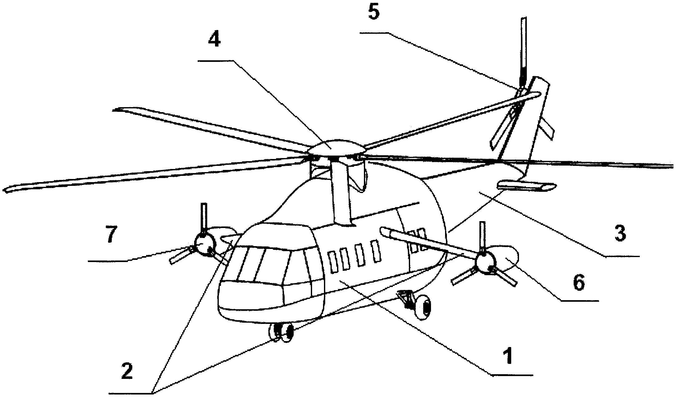
На фиг.1 - скоростной комбинированный вертолет, аксонометрическая проекция;In Fig.1 - high-speed combined helicopter, axonometric projection;
На фиг.2 - то же при повернутом положении консолей крыла;Figure 2 - the same with the rotated position of the wing consoles;
На фиг.3 - схематическое изображение систем вертолета и их связей.Figure 3 is a schematic illustration of a helicopter systems and their connections.
Скоростной комбинированный вертолет включает фюзеляж 1 с крылом, состоящим из правой и левой консолей 2, и с хвостовой балкой 3, а также несущий винт 4 и рулевой винт 5 (фиг.1, 2). На консолях 2 крыла расположены левый и правый тяговые движители, которые могут быть выполнены реактивными, турбореактивными или турбовентиляторными, а в данном примере выполнения - двигатели 6 и 7 с воздушными винтами (фиг.1, 2). На схеме (фиг.3) изображены: силовая установка 8 вертолета, топливная система 9 и система управления силовой установкой 10, причем топливная система 9 с помощью трубопроводов с разъемами 11 связана с двигателями 6 и 7. В свою очередь система управления 10 силовой установкой связана через штепсельные разъемы 12 с двигателями 6 и 7.High-speed combined helicopter includes a fuselage 1 with a wing consisting of a right and left consoles 2, and with a tail boom 3, as well as a rotor 4 and a tail rotor 5 (Figs. 1, 2). On the wing consoles 2 there are left and right traction drives, which can be made jet, turbojet or turbofan, and in this embodiment, engines 6 and 7 with propellers (Fig. 1, 2). The diagram (figure 3) shows: the helicopter power plant 8, the fuel system 9 and the power plant control system 10, and the fuel system 9 is connected to the engines 6 and 7 via pipelines with connectors 11. In turn, the power plant control system 10 is connected through plug connectors 12 with motors 6 and 7.
Консоли 2 крыла установлены относительно фюзеляжа 1 с помощью поворотно-разъемных узлов 13 и 14. Поворотно-разъемные узлы 13 и 14 выполнены с возможностью демонтажа консолей 2 крыла (вместе с установленными на них двигателями 6 и 7) на стоянке, а также с возможностью поворота и установки консолей 2 на стоянке в вертикальное положение (для полета вертолета в режиме вертикального взлета и посадки) или в положение по-самолетному (для скоростного горизонтального полета). В полете поворотно-разъемные узлы 13 и 14 обеспечивают возможность поворота консолей 2 в вертикальное положение и обратно, а также возможность аварийного сброса, для чего поворотно-разъемные узлы 13 и 14 связаны с системой управления силовой установкой 10 и могут содержать установленные в фюзеляже электромеханический или электрогидравлический привод поворота силового кронштейна (не показано), соединенного с ответным силовым элементом консоли 2 крыла. Присоединение и отсоединение консолей 2 крыла от кронштейнов может осуществляться с помощью пироболтов (не показано).The wing consoles 2 are mounted relative to the fuselage 1 with the help of rotary-detachable units 13 and 14. The rotary-detachable units 13 and 14 are made with the possibility of dismantling the wing consoles 2 (together with the engines 6 and 7 mounted on them) in the parking lot, as well as with the possibility of rotation and installation of the consoles 2 in the parking position in the vertical position (for helicopter flight in the vertical take-off and landing mode) or in the airplane position (for high-speed horizontal flight). In flight, the rotary-detachable nodes 13 and 14 provide the ability to rotate the consoles 2 to a vertical position and vice versa, as well as the possibility of emergency reset, for which the rotary-detachable nodes 13 and 14 are connected to the control system of the power plant 10 and may contain electromechanical or installed in the fuselage electro-hydraulic drive rotation of the power bracket (not shown) connected to the reciprocal power element of the console 2 of the wing. Attaching and disconnecting the wing consoles 2 from the brackets can be done using pyro bolts (not shown).
Скоростной комбинированный вертолет функционирует следующим образом. В зависимости от полетного задания на стоянке устанавливаются в рабочее положение (или демонтируются) консоли 2 крыла вместе с установленными на них тяговыми двигателями 6, 7. С помощью поворотно-разъемных узлов 13 и 14 и разъемов 11 и 12 тяговые двигатели 6 и 7 подсоединяются (или отсоединяются) к системе управления 10 и к топливной системе 9 вертолета (фиг.1, 2, 3). Со снятыми консолями 2 крыла скоростной комбинированный вертолет совершает обычный полет в не скоростном режиме. С установленными консолями 2 крыла (с тяговыми двигателями 6 и 7 на них) летчик перед взлетом/посадкой с помощью правого 13 и левого 14 поворотно-разъемных узлов устанавливает консоли 2 крыла (вместе с тяговыми двигателями 6 и 7) в вертикальное положение (фиг.2) для улучшения условий обтекания их потоком воздуха от несущего винта 4 вертолета. Как правило, тяговые двигатели 6 и 7 при этом находятся в выключенном состоянии.High-speed combined helicopter operates as follows. Depending on the flight mission in the parking lot, the wing consoles 2 are installed in the working position (or dismantled) together with the traction motors 6, 7 installed on them. Using the rotary-split units 13 and 14 and the connectors 11 and 12, the traction motors 6 and 7 are connected ( or disconnected) to the control system 10 and to the fuel system 9 of the helicopter (figures 1, 2, 3). With the 2 wing consoles removed, a high-speed combined helicopter performs a normal flight in non-high-speed mode. With the wing consoles 2 installed (with traction engines 6 and 7 on them), the pilot sets the wing consoles 2 (together with traction engines 6 and 7) in the vertical position before take-off / landing using the right 13 and left 14 rotary-detachable assemblies (Fig. 2) to improve the conditions around their flow of air from the rotor 4 of the helicopter. As a rule, traction motors 6 and 7 are in this case off.
При необходимости увеличить подъемную силу скоростного комбинированного вертолета в режимах взлета и посадки (например, из-за увеличенной взлетной массы) летчик, используя систему управления 10 силовой установкой, запускает тяговые двигатели 6 и 7.If necessary, increase the lifting force of a high-speed combined helicopter in take-off and landing modes (for example, due to increased take-off weight), the pilot, using the control system 10 of the power plant, starts the traction engines 6 and 7.
После набора вертолетам определенной высоты летчик, управляя несущим винтом 4, переводит скоростной комбинированный вертолет в режим горизонтального полета, предварительно переведя консоли 2 крыла в горизонтальное положение посредством поворотно-разъемных узлов 13 и 14. Максимальная скорость горизонтального полета достигается при максимальной тяге тяговых двигателей 6 и 7 и пониженной скорости вращения несущего винта 4.After a set of helicopters of a certain height, the pilot, controlling the main rotor 4, puts the high-speed combined helicopter into horizontal flight mode, having previously converted the wing consoles 2 to the horizontal position by means of rotary-detachable units 13 and 14. The maximum horizontal speed is achieved with maximum thrust of traction motors 6 and 7 and reduced rotor speed 4.
При отказе силовой установки 8 вертолета летчик имеет возможность использовать горизонтальную тягу тяговых двигателей 6 и 7 для осуществления безопасной посадки скоростного комбинированного вертолета по-самолетному или для разгона скоростного комбинированного вертолета для выхода его на режим авторотации.In case of failure of the helicopter power unit 8, the pilot has the opportunity to use the horizontal thrust of the traction engines 6 and 7 to safely land a high-speed combined helicopter in an airplane or to disperse a high-speed combined helicopter to enter autorotation mode.
При отказе одного или двух тяговых двигателей 6 и 7 или других обстоятельствах летчик имеет возможность, управляя поворотно-разъемными узлами 13 и 14, сбросить правую и левую консоли 2 крыла вместе с тяговыми двигателями 6 и 7. При этом после, срабатывания пироболтов, консоли 2 отсоединяются от поворотного кронштейна, и разъемы 11 и 12 расстыковываются. Вертолет осуществляет дальнейший полет в обычном не скоростном режиме.In case of failure of one or two traction engines 6 and 7 or other circumstances, the pilot has the opportunity, by controlling the rotary-split units 13 and 14, to reset the right and left wing console 2 along with the traction motors 6 and 7. In this case, after the pyro-bolts are triggered, the console 2 disconnected from the swivel bracket, and connectors 11 and 12 are undocked. The helicopter carries out further flight in the usual non-high-speed mode.
Claims (1)
Priority Applications (1)
| Application Number | Priority Date | Filing Date | Title |
|---|---|---|---|
| RU2011130443/11U RU110715U1 (en) | 2011-07-22 | 2011-07-22 | SPEED COMBINED HELICOPTER |
Applications Claiming Priority (1)
| Application Number | Priority Date | Filing Date | Title |
|---|---|---|---|
| RU2011130443/11U RU110715U1 (en) | 2011-07-22 | 2011-07-22 | SPEED COMBINED HELICOPTER |
Publications (1)
| Publication Number | Publication Date |
|---|---|
| RU110715U1 true RU110715U1 (en) | 2011-11-27 |
Family
ID=45318507
Family Applications (1)
| Application Number | Title | Priority Date | Filing Date |
|---|---|---|---|
| RU2011130443/11U RU110715U1 (en) | 2011-07-22 | 2011-07-22 | SPEED COMBINED HELICOPTER |
Country Status (1)
| Country | Link |
|---|---|
| RU (1) | RU110715U1 (en) |
Cited By (10)
| Publication number | Priority date | Publication date | Assignee | Title |
|---|---|---|---|---|
| RU2480379C1 (en) * | 2012-02-20 | 2013-04-27 | Дмитрий Сергеевич Дуров | High speed and maneuverability rotorcraft |
| RU2539679C1 (en) * | 2013-11-19 | 2015-01-20 | Открытое Акционерное Общество "Московский Вертолетный Завод Им. М.Л. Миля" | High-speed rotary-wing aircraft |
| RU2551703C2 (en) * | 2012-05-21 | 2015-05-27 | Эйрбас Хеликоптерс | Control over wing flaps and rudder of hybrid helicopter |
| RU2551830C2 (en) * | 2012-05-21 | 2015-05-27 | Эйрбас Хеликоптерс | Control over wing flaps and horizontal stabiliser of hybrid helicopter |
| RU2556055C2 (en) * | 2012-08-27 | 2015-07-10 | Эйрбас Хеликоптерс | Method for rendering assistance to pilot of single-engine rotary-wing aircraft in autorotation mode |
| RU2568234C2 (en) * | 2014-04-04 | 2015-11-10 | Михаил Николаевич Колеватов | Hybrid airborne vehicle |
| WO2017064717A1 (en) * | 2015-10-13 | 2017-04-20 | Newrocket Ltd. | Thrusting rockets for enhancing emergency autorotation |
| RU2629482C1 (en) * | 2016-03-29 | 2017-08-29 | Дмитрий Сергеевич Дуров | Unmanned combined helicopter |
| RU2631728C1 (en) * | 2015-07-16 | 2017-09-26 | Эйрбас Хеликоптерс | Combined aircraft equipped with moment compensation device and method for forming additional rotation moment for mentioned aircraft |
| RU2797468C1 (en) * | 2022-08-01 | 2023-06-06 | Василий Владимирович Яценко | Aircraft |
-
2011
- 2011-07-22 RU RU2011130443/11U patent/RU110715U1/en active
Cited By (12)
| Publication number | Priority date | Publication date | Assignee | Title |
|---|---|---|---|---|
| RU2480379C1 (en) * | 2012-02-20 | 2013-04-27 | Дмитрий Сергеевич Дуров | High speed and maneuverability rotorcraft |
| RU2551703C2 (en) * | 2012-05-21 | 2015-05-27 | Эйрбас Хеликоптерс | Control over wing flaps and rudder of hybrid helicopter |
| RU2551830C2 (en) * | 2012-05-21 | 2015-05-27 | Эйрбас Хеликоптерс | Control over wing flaps and horizontal stabiliser of hybrid helicopter |
| RU2556055C2 (en) * | 2012-08-27 | 2015-07-10 | Эйрбас Хеликоптерс | Method for rendering assistance to pilot of single-engine rotary-wing aircraft in autorotation mode |
| RU2539679C1 (en) * | 2013-11-19 | 2015-01-20 | Открытое Акционерное Общество "Московский Вертолетный Завод Им. М.Л. Миля" | High-speed rotary-wing aircraft |
| RU2568234C2 (en) * | 2014-04-04 | 2015-11-10 | Михаил Николаевич Колеватов | Hybrid airborne vehicle |
| RU2631728C1 (en) * | 2015-07-16 | 2017-09-26 | Эйрбас Хеликоптерс | Combined aircraft equipped with moment compensation device and method for forming additional rotation moment for mentioned aircraft |
| WO2017064717A1 (en) * | 2015-10-13 | 2017-04-20 | Newrocket Ltd. | Thrusting rockets for enhancing emergency autorotation |
| US20180319486A1 (en) * | 2015-10-13 | 2018-11-08 | Newrocket Ltd. | Thrusting rockets for enhancing emergency autorotation |
| EP3362357A4 (en) * | 2015-10-13 | 2019-06-12 | Newrocket Ltd. | Thrusting rockets for enhancing emergency autorotation |
| RU2629482C1 (en) * | 2016-03-29 | 2017-08-29 | Дмитрий Сергеевич Дуров | Unmanned combined helicopter |
| RU2797468C1 (en) * | 2022-08-01 | 2023-06-06 | Василий Владимирович Яценко | Aircraft |
Similar Documents
| Publication | Publication Date | Title |
|---|---|---|
| RU110715U1 (en) | SPEED COMBINED HELICOPTER | |
| RU2520843C2 (en) | High-speed aircraft with long flight range | |
| EP3564122B1 (en) | Hybrid tiltrotor drive system | |
| CN202728576U (en) | Transformable composite aircraft formed by fixed wing and electric multi-propeller | |
| RU2507121C1 (en) | High-speed rotary-wing aircraft | |
| US20180141652A1 (en) | Convertible airplane with exposable rotors | |
| CN202754143U (en) | Rotating engine vertical take-off and landing aircraft | |
| CN202728575U (en) | Composite aircraft with fixed wing and electric multi-rotor-wing combined | |
| CN108698690A (en) | UAV with the wing plate component for providing effective vertical takeoff and throwing power | |
| CN202728574U (en) | Composite aircraft with fixed wing and electric multiple propellers combined and with helicopter function | |
| CN103287576A (en) | Tailless layout single tail seat type vertical take-off and landing aircraft | |
| GB2409845A (en) | Tilt-rotor aircraft changeable between vertical lift and forward flight modes | |
| JP2014528382A (en) | Aircraft combining fixed wing and electric multi-rotor | |
| KR20090057504A (en) | Taking off and landing airplane using variable rotary wings | |
| WO2009149592A1 (en) | Vertical takeoff and landing airplane | |
| RU2635431C1 (en) | Convertible aircraft | |
| RU2521090C1 (en) | High-speed turboelectric helicopter | |
| RU2548304C1 (en) | Multirotor convertible high-speed helicopter | |
| RU2657706C1 (en) | Convertiplane | |
| RU2674622C1 (en) | Convertiplane | |
| RU139040U1 (en) | AIRCRAFT "LANNER" | |
| RU2652863C1 (en) | High-speed hybrid helicopter-aircraft | |
| US11433093B2 (en) | Compact gyroplane employing torque compensated main rotor and hybrid power train | |
| RU146302U1 (en) | SPEED COMBINED HELICOPTER | |
| KR20030049796A (en) | Three-Fan Lifted Vertical Take-off and Landing Aircraft |
Legal Events
| Date | Code | Title | Description |
|---|---|---|---|
| PD9K | Change of name of utility model owner |