RU106934U1 - LIGHTING DEVICE - Google Patents
LIGHTING DEVICE Download PDFInfo
- Publication number
- RU106934U1 RU106934U1 RU2011112325/07U RU2011112325U RU106934U1 RU 106934 U1 RU106934 U1 RU 106934U1 RU 2011112325/07 U RU2011112325/07 U RU 2011112325/07U RU 2011112325 U RU2011112325 U RU 2011112325U RU 106934 U1 RU106934 U1 RU 106934U1
- Authority
- RU
- Russia
- Prior art keywords
- light guide
- guide element
- light
- tapering
- light flux
- Prior art date
Links
- 230000004907 flux Effects 0.000 claims abstract description 46
- 239000000835 fiber Substances 0.000 claims abstract description 11
- 239000000463 material Substances 0.000 claims abstract description 8
- 230000005855 radiation Effects 0.000 description 24
- 238000005326 angular distribution function Methods 0.000 description 5
- 230000008859 change Effects 0.000 description 4
- 238000000149 argon plasma sintering Methods 0.000 description 2
- 238000005315 distribution function Methods 0.000 description 2
- 239000011521 glass Substances 0.000 description 2
- 239000002245 particle Substances 0.000 description 2
- 230000004075 alteration Effects 0.000 description 1
- 238000004364 calculation method Methods 0.000 description 1
- 238000006243 chemical reaction Methods 0.000 description 1
- 238000010276 construction Methods 0.000 description 1
- 230000007423 decrease Effects 0.000 description 1
- 238000010586 diagram Methods 0.000 description 1
- 239000006185 dispersion Substances 0.000 description 1
- 239000002657 fibrous material Substances 0.000 description 1
- 238000005286 illumination Methods 0.000 description 1
- 230000008447 perception Effects 0.000 description 1
- 230000007704 transition Effects 0.000 description 1
Landscapes
- Light Guides In General And Applications Therefor (AREA)
Abstract
1. Осветительный прибор, содержащий световодный элемент, изготовленный удлиненной формы и имеющий в, по меньшей мере, одном продольном сечении основание и две боковые стороны, сужающиеся от основания к вершине, при этом основание каждого из упомянутых продольных сечений расположено на торце световодного элемента, и направленный световой источник, расположенный на торце световодного элемента, для направления светового потока в этот торец, при этом угол между направлением светового потока от направленного светового источника и направлением удлинения световодного элемента выбран в таком диапазоне, чтобы световой поток испытывал, по меньшей мере, одно полное внутреннее отражение от упомянутых сужающихся боковых сторон в упомянутом, по меньшей мере, одном продольном сечении световодного элемента и выходил через одну из этих сужающихся боковых сторон после, по меньшей мере, одного из упомянутых полных внутренних отражений. ! 2. Прибор по п.1, в котором коэффициент преломления материала световодного элемента, а также пределы углов между упомянутыми сужающимися боковыми сторонами в тех из упомянутых продольных сечений, в которых происходит распространение светового потока, и упомянутый диапазон углов, под которыми световой поток входит в световодный элемент, выбраны так, чтобы световой поток выходил через одну и ту же из сужающихся боковых сторон. ! 3. Прибор по п.2, в котором световодный элемент выполнен изогнутым так, что в, по меньшей мере, одном из упомянутых продольных сечений, в которых происходит распространение светового потока в световодном элементе, образуется плавно сужающаяся фигура с выпуклостью в � 1. A lighting device comprising a fiber guide element made of an elongated shape and having at least one longitudinal section of the base and two sides tapering from the base to the top, the base of each of said longitudinal sections being located at the end of the fiber guide element, and a directional light source located at the end of the light guide element for directing the light flux to this end, the angle between the direction of the light flux from the directional light source and directed the extension length of the light guide member is selected in such a range that the light flux experiences at least one total internal reflection from said tapering sides in said at least one longitudinal section of the light guide member and exits through one of these tapering sides after at least one of said total internal reflections. ! 2. The device according to claim 1, in which the refractive index of the material of the light guide member, as well as the limits of the angles between said tapering side sides in those of said longitudinal sections in which the light flux propagates, and said range of angles at which the light flux enters the light guide member is selected so that the light flux exits through the same of the tapering sides. ! 3. The device according to claim 2, in which the light guide element is made curved so that in at least one of the aforementioned longitudinal sections, in which the light flux propagates in the light guide element, a smoothly narrowing figure with a bulge in �
Description
Область техники, к которой относится полезная модельThe technical field to which the utility model relates.
Настоящая полезная модель относится к осветительной технике, в частности, к осветительному прибору, которые позволяют получить экономичные, комфортные для восприятия глазом, однородные световые потоки при использовании светодиодных источников света для освещения жилых, технологических и технических помещений.This utility model relates to lighting equipment, in particular, to a lighting device, which allows to obtain economical, comfortable for the perception of the eye, uniform light flux when using LED light sources for lighting residential, technological and technical rooms.
Уровень техникиState of the art
В настоящее время известны световые приборы, в которых используются светодиодные источники света, в которых для обеспечения более равномерного светового потока применяется диффузионное рассеяние света. См., к примеру, патенты РФ на полезную модель №95886 (опубл. 10.07.2010) и №93929 (опубл. 10.05.2010), а также заявку на патент США №2011/0042700 (опубл. 24.02.2011).Light devices are currently known in which LED light sources are used, in which diffuse light scattering is used to provide a more uniform light flux. See, for example, RF patents for utility model No. 95886 (publ. 10.07.2010) and No. 93929 (publ. 10.05.2010), as well as application for US patent No. 2011/0042700 (publ. 24.02.2011).
Недостаток таких технических решений состоит в наличии рассеивающих частиц в материале световодного элемента, пропускающего свет от светодиодов.The disadvantage of such technical solutions is the presence of scattering particles in the material of the light guide element transmitting light from the LEDs.
Известна также фокусировка светового потока различными линзами, как, например, в патенте РФ на полезную модель №95181 (опубл. 10.06.2010). Однако такая фокусировка, хотя при ней не используются светорассеивающие частицы в материале световодного элемента, не в состоянии обеспечить равномерное освещение вследствие присущих любым линзам искажений (аберраций).Also known is the focusing of the luminous flux with various lenses, as, for example, in the patent of the Russian Federation for utility model No. 95181 (published on June 10, 2010). However, such focusing, although it does not use light-scattering particles in the material of the light guide element, is not able to provide uniform illumination due to distortions (aberrations) inherent in any lens.
Раскрытие полезной моделиUtility Model Disclosure
Таким образом, цель настоящей полезной модели состоит в том, чтобы обеспечить:Thus, the purpose of this utility model is to provide:
- преобразование световых пучков от источников в один или несколько выходящих световых пучков большего поперечного сечения;- the conversion of light beams from sources into one or more outgoing light beams of a larger cross section;
- более равномерную яркость выходящих пучков по сечению;- a more uniform brightness of the emerging beams over the cross section;
- высокий КПД по вводу-выводу светового излучения; и- high efficiency in input-output of light radiation; and
- заданное направление (направления) выходящих пучков.- a given direction (directions) of the emerging beams.
Для достижения указанной выше цели в объекте настоящей полезной модели предложен осветительный прибор, содержащий световодный элемент, изготовленный удлиненной формы и имеющий в по меньшей мере одном продольном сечении основание и две боковые стороны, сужающиеся от основания к вершине, при этом основание каждого из продольных сечений расположено на торце световодного элемента, и направленный световой источник, расположенный на торце световодного элемента для направления светового потока в этот торец, при этом угол между направлением светового потока от направленного светового источника и направлением удлинения световодного элемента выбран в таком диапазоне, чтобы световой поток испытывал по меньшей мере одно полное внутреннее отражение от упомянутых сужающихся боковых сторон в по меньшей мере одном продольном сечении световодного элемента и выходил через одну из этих сужающихся боковых сторон после по меньшей мере одного из полных внутренних отражений.To achieve the above goal, the object of this utility model proposes a lighting device containing a light guide element made of an elongated shape and having at least one longitudinal section of the base and two sides tapering from the base to the top, with the base of each of the longitudinal sections at the end of the light guide element, and a directional light source located at the end of the light guide element to direct the light flux to this end, the angle between the direction the luminous flux from the directional light source and the extension direction of the light guide member is selected in such a range that the light flux experiences at least one total internal reflection from said tapering sides in at least one longitudinal section of the light guide member and exits through one of these tapering sides after at least one of the total internal reflections.
Особенность осветительного прибора по настоящей полезной модели состоит в том, что коэффициент преломления материала световодного элемента, а также пределы углов между сужающимися боковыми сторонами в тех из продольных сечений, в которых происходит распространение светового потока, и диапазон углов, под которыми световой поток входит в световодный элемент, могут быть выбраны так, чтобы световой поток выходил через одну и ту же из сужающихся боковых сторон.A feature of the lighting device according to this utility model is that the refractive index of the material of the light guide element, as well as the limits of the angles between the tapering sides in those longitudinal sections in which the light flux propagates, and the range of angles at which the light flux enters the light guide element, can be selected so that the luminous flux exits through the same of the tapering sides.
Еще одна особенность осветительного прибора по настоящей полезной модели состоит в том, что световодный элемент может быть выполнен изогнутым так, что в по меньшей мере одном из продольных сечений, в которых происходит распространение светового потока в световодном элементе, образуется плавно сужающаяся фигура с выпуклостью в сторону выхода светового потока из световодного элемента.Another feature of the lighting device according to the present utility model is that the light guide element can be made curved so that in at least one of the longitudinal sections in which the light flux propagates in the light guide element, a smoothly tapering figure is formed with a bulge to the side light output from the light guide member.
При этом световодный элемент может быть выполнен в виде плавно изогнутой пластины, полученной параллельным переносом плавно сужающейся фигуры в направлении, перпендикулярном плоскости этой фигуры, а на торце световодного элемента может быть размещено множество направленных световых источников. Либо световодный элемент может быть выполнен в виде тела вращения, полученного вращением плавно сужающейся фигуры вокруг оси, лежащей в плоскости этой фигуры и вне этой фигуры вблизи ее острого конца, а на торце световодного элемента может быть размещено множество направленных световых источников.In this case, the light guide element can be made in the form of a smoothly curved plate obtained by parallel transfer of a smoothly tapering figure in the direction perpendicular to the plane of this figure, and many directional light sources can be placed at the end of the light guide element. Or the light guide element can be made in the form of a body of revolution, obtained by rotating a smoothly tapering figure around an axis lying in the plane of this figure and outside this figure near its sharp end, and many directional light sources can be placed at the end of the light guide element.
Еще одна особенность осветительного прибора по настоящей полезной модели состоит в том, что световодный элемент может быть выполнен изогнутым так, что в по меньшей мере одном из продольных сечений, в которых происходит распространение светового потока в световодном элементе, образуется многосторонняя сужающаяся фигура, ограниченная ломаными линиями, имеющими выпуклость в сторону выхода светового потока из световодного элемента.Another feature of the lighting device according to the present utility model is that the light guide element can be made curved so that in at least one of the longitudinal sections in which the light flux propagates in the light guide element, a multilateral tapering figure is formed, limited by broken lines having a bulge towards the exit of the light flux from the light guide element.
При этом световодный элемент может быть выполнен в виде изогнутой с изломами пластины, полученной параллельным переносом многосторонней сужающейся фигуры в направлении, перпендикулярном плоскости этой фигуры, а на торце световодного элемента могут быть размещены множество направленных световых источников. Либо световодный элемент может быть выполнен в виде тела вращения, полученного вращением многосторонней сужающейся фигуры вокруг оси, лежащей в плоскости этой фигуры и вне этой фигуры вблизи ее острого конца, а на торце световодного элемента может быть размещено множество направленных световых источников.In this case, the light guide element can be made in the form of a plate bent with kinks, obtained by parallel transfer of a multilateral tapering figure in the direction perpendicular to the plane of this figure, and a lot of directional light sources can be placed at the end of the light guide element. Or, the light guide element can be made in the form of a body of revolution obtained by rotating a multilateral tapering figure around an axis lying in the plane of this figure and outside this figure near its sharp end, and many directional light sources can be placed at the end of the light guide element.
Еще одна особенность осветительного прибора по настоящей полезной модели состоит в том, что направленные световые источники могут быть размещены на торце световодного элемента равномерно.Another feature of the lighting device according to this utility model is that directional light sources can be placed uniformly at the end of the light guide element.
Наконец, еще одна особенность осветительного прибора по настоящей полезной модели состоит в том, что в качестве по меньшей мере одного направленного светового источника может быть использован светодиод.Finally, another feature of the lighting device according to the present utility model is that an LED can be used as at least one directional light source.
Краткое описание чертежейBrief Description of the Drawings
Полезная модель иллюстрируется сопровождающими чертежами.The utility model is illustrated in the accompanying drawings.
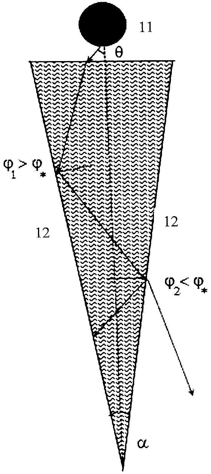
Фиг.1 представляет вид в перечном сечении световодного элемента в соответствии с одним вариантом осуществления настоящей полезной модели.1 is a cross-sectional view of a light guide member in accordance with one embodiment of the present utility model.
Фиг.2 показывает схему распространения лучей в эллипсе с отношением длин полуосей a/b=2.Figure 2 shows the pattern of propagation of rays in an ellipse with the ratio of the lengths of the axle axles a / b = 2.
Фиг.3 иллюстрирует исходное распределение светового потока от точечного источника.Figure 3 illustrates the initial distribution of the light flux from a point source.
Фиг.4 показывает долю η излучения, выходящего наружу из эллипса в зависимости от угла φ наклона пучка света относительно оси, соединяющей фокусы эллипса; указаны точки 1-4, соответствующие углам наклона, при которых наружу выходит 15% полной мощности источника.Figure 4 shows the proportion η of radiation emerging from the ellipse depending on the angle φ of the tilt of the light beam relative to the axis connecting the foci of the ellipse; points 1–4 are shown, which correspond to the tilt angles at which 15% of the total source power goes out.
Фиг.5 демонстрирует участки А1В1 и A2B2 поверхности эллиптической линзы из стекла, через которые наружу выходит 0,15 мощности источника в фокусе 1.Figure 5 shows the sections A 1 B 1 and A 2 B 2 of the surface of an elliptical lens made of glass, through which 0.15 of the source power in focus 1 comes out.
Фиг.6 представляет схему построения участка А2В2 нижней (нерабочей) поверхности световодного элемента с полным внутренним отражением; фокусы 1 большого и малого эллипсов совпадают.6 is a diagram of the construction of the plot And 2 In 2 the lower (non-working) surface of the light guide element with total internal reflection; the tricks 1 of the large and small ellipses coincide.
Фиг.7 показывает углы падения лучей пучка на поверхность А2В2 по Фиг.6.Fig.7 shows the angles of incidence of the beam on the surface And 2 In 2 in Fig.6.
Фиг.8 иллюстрирует угловые функции распределения светового пучка в световодном элементе по Фиг.6.Fig. 8 illustrates the angular distribution functions of the light beam in the light guide member of Fig. 6.
Фиг.9 дает условный вид световодного элемента с фиксированной мощностью (15% от общей), выходящей при каждом отражении светового пучка от верхней (рабочей) поверхности, при не выходе излучения через нижнюю поверхность (угловые соотношения сохранены точно) согласно настоящей полезной модели.Fig.9 gives a conditional view of a light guide element with a fixed power (15% of the total) emerging at each reflection of the light beam from the upper (working) surface, if radiation does not exit through the lower surface (angular relations are stored exactly) according to the present utility model.
Фиг.10 показывает исходную (0) и угловые функции распределения после каждого отражения 1-11 в световодном элементе по Фиг.9.FIG. 10 shows the initial (0) and angular distribution functions after each reflection 1-11 in the light guide member of FIG. 9.
Фиг.11 демонстрирует световодный элемент согласно возможному варианту осуществления настоящей полезной модели.11 shows a light guide member according to a possible embodiment of the present utility model.
Подробное описание вариантов осуществления полезной моделиDetailed Description of Embodiments of a Utility Model
Осветительный прибор согласно настоящей полезной модели содержит световодный элемент и по меньшей мере один направленный световой источник. Для начала рассмотрим световодный элемент с сужающимися от основания боковыми сторонами (11) в поперечном сечении, которое условно показано на Фиг.1. Это может быть клиновидный либо конусовидный световодный элемент, то есть изготовленный удлиненной формы и имеющий в по меньшей мере одном продольном сечении основание и две боковые стороны, сужающиеся от основания к вершине, при этом основание каждого из упомянутых продольных сечений расположено на торце световодного элемента.A lighting device according to the present utility model comprises a light guide member and at least one directional light source. To begin with, we consider a light guide element with the sides (11) tapering from the base in a cross section, which is conventionally shown in FIG. This can be a wedge-shaped or cone-shaped light guide element, that is, made of elongated shape and having a base in at least one longitudinal section and two sides tapering from the base to the top, with the base of each of the said longitudinal sections being located at the end of the light guide element.
В световодном элементе с поперечным сечением по Фиг.1 луч от светового источника (12), расположенный на торце световодного элемента для направления светового потока в этот торец и имеющий угол θ относительно продольной оси световодного элемента, испытывает первое отражение под углом φ1=π/2-θ-α/2, от левой рабочей поверхности световода и проходит дальше. После второго отражения (отражения от правой рабочей поверхности) φ2=π/2-θ-3α/2, после k-го отражения угол будет равен φk=π/2-θ-α(k-1/2), т.е. φk уменьшается с каждым отражением. Таким образом, при некотором отражении k*(θ) (на Фиг.1 k*(θ)=2) окажется, что , где φ* - угол полного внутреннего отражения для материала световода с показателем преломления n. При отражении k* и последующих свет начнет выходить из световода наружу. Таким образом, на начальном этапе распространения света, при k<k*(θ) происходит его перенос вдоль направления удлинения световода без выхода наружу, а затем, при k≥k*(θ) - и перенос и выход излучения наружу. Лучи источника с большим углом θ относительно продольной оси световода будут выходить ближе к входному торцу световода, а лучи с меньшим θ - дальше от этого торца.In a light guide element with a cross section in FIG. 1, a beam from a light source (12) located at the end of the light guide element to direct the light flux to this end and having an angle θ relative to the longitudinal axis of the light guide element experiences a first reflection at an angle φ 1 = π / 2-θ-α / 2, from the left working surface of the fiber and passes further. After the second reflection (reflection from the right working surface) φ 2 = π / 2-θ-3α / 2, after the k-th reflection the angle will be equal to φ k = π / 2-θ-α (k-1/2), t .e. φ k decreases with each reflection. Thus, with some reflection k * (θ) (in Fig. 1 k * (θ) = 2) it turns out that where φ * is the angle of total internal reflection for the fiber material with a refractive index n. Upon reflection of k * and subsequent light starts to go out of the fiber. Thus, at the initial stage of the propagation of light, for k <k * (θ), it is transported along the extension direction of the fiber without going outside, and then, for k≥k * (θ), the radiation is transmitted and exited. The rays of the source with a large angle θ relative to the longitudinal axis of the fiber will exit closer to the input end of the fiber, and rays with a smaller θ will be farther from this end.
То есть угол между направлением светового потока от направленного светового источника и направлением удлинения световодного элемента выбран в таком диапазоне, чтобы световой поток испытывал по меньшей мере одно полное внутреннее отражение от упомянутых сужающихся боковых сторон в упомянутом по меньшей мере одном продольном сечении световодного элемента и выходил через одну из этих сужающихся боковых сторон после по меньшей мере одного из упомянутых полных внутренних отражений. Таким образом, обеспечивают равномерность выхода излучения с боковых поверхностей световода.That is, the angle between the direction of the light flux from the directional light source and the extension direction of the light guide member is selected in such a range that the light flux experiences at least one total internal reflection from said tapering sides in said at least one longitudinal section of the light guide member and exits through one of these tapering sides after at least one of said total internal reflections. Thus, they ensure uniform output of radiation from the side surfaces of the fiber.
Если теперь коэффициент преломления материала световодного элемента, а также пределы углов между сужающимися боковыми сторонами (11) в тех продольных сечениях, где происходит распространение светового потока, а также диапазон углов, под которыми световой поток входит в световодный элемент, выбрать так, чтобы световой поток выходил через одну и ту же из сужающихся боковых сторон (11), получится световодный элемент с излучением только с одной стороны. Указанный подбор коэффициента преломления и соответствующих углов представляет собой достаточно сложную задачу, которая в каждом конкретном случае решается с помощью математического моделирования.If now the refractive index of the material of the light guide element, as well as the limits of the angles between the tapering sides (11) in those longitudinal sections where the light flux propagates, as well as the range of angles at which the light flux enters the light guide element, choose so that the light flux out through the same of the tapering sides (11), you get a light guide element with radiation from only one side. The specified selection of the refractive index and the corresponding angles is a rather complicated task, which in each case is solved using mathematical modeling.
Приведенный на Фиг.1 световодный элемент можно изогнуть так, что хотя бы в одном из продольных сечений, где происходит распространение светового потока в световодном элементе, образуется плавно сужающаяся фигура с выпуклостью в сторону выхода светового потока из световодного элемента.The light guide element shown in FIG. 1 can be bent so that at least in one of the longitudinal sections where the light flux propagates in the light guide element, a smoothly tapering figure is formed with a bulge towards the exit of the light flux from the light guide element.
Рассмотрим теперь случай, когда изогнутые линии в продольном сечении такого световодного элемента представляют собой отрезки эллипсов. Для простоты, сначала обратимся к Фиг.2, где точечный источник (12) света, дающий световой поток в пределах угла 2θ0, помещен в одном из фокусов эллипса. Эллипс выполнен из материала с показателем преломления n1, снаружи находится материал с показателем преломления n2<n1. Направление пучка источника (12) относительно поверхности эллипса определяется углом φ наклона правой границы пучка относительно горизонтальной оси, соединяющей фокусы эллипса.Let us now consider the case when the curved lines in the longitudinal section of such a light guide element are segments of ellipses. For simplicity, we first turn to Figure 2, where a point source of light (12) giving a luminous flux within an angle of 2θ 0 is placed at one of the focal points of the ellipse. The ellipse is made of a material with a refractive index n 1 , outside is a material with a refractive index n 2 <n 1 . The direction of the source beam (12) relative to the surface of the ellipse is determined by the angle φ of the slope of the right border of the beam relative to the horizontal axis connecting the foci of the ellipse.
Некоторый луч из пучка имеет угол φ+θ относительно горизонтальной оси. Соответствующий этому лучу отраженный луч имеет угол φ'+θ', где φ' - угол наклона, относительно горизонтальной оси, крайнего в пучке слева отраженного луча, а θ' отсчитывается от этого луча. Поскольку углы ϕ одинаковы, угол падения выбранного луча .Some beam from the beam has an angle φ + θ relative to the horizontal axis. The reflected beam corresponding to this beam has an angle φ '+ θ', where φ 'is the angle of inclination, relative to the horizontal axis, of the extreme reflected beam in the beam to the left, and θ' is counted from this beam. Since the angles ϕ are the same, the angle of incidence of the selected beam .
Чтобы определить связь между углами θ и θ' воспользуемся уравнением эллипса в полярных координатах [1]To determine the relationship between the angles θ and θ 'we use the equation of the ellipse in polar coordinates [1]
Как видно из Фиг.2, для каждого луча в пучке источника выполняется соотношение ρcos(φ+θ)+ρ'cos(φ'+θ')=2ae. Тогда, подставляя в это соотношение выражение (1), находимAs can be seen from Figure 2, for each ray in the source beam, the relation ρcos (φ + θ) + ρ'cos (φ '+ θ') = 2ae holds. Then, substituting expression (1) into this relation, we find
cos(φ'+θ')=F(φ+θ), cos (φ '+ θ') = F (φ + θ),
где, как следует из Фиг.2,where, as follows from Figure 2,
cos(φ')=F(φ+2θ0).cos (φ ') = F (φ + 2θ 0 ).
Выражение (2) устанавливает связь между θ и θ'.Expression (2) establishes a relationship between θ and θ '.
Для определенности предположим, что световодный элемент (и эллипс на Фиг.2) сделаны из стекла n1≡n=1.55, вокруг которого находится воздух с n2=1. Источник (12) создает световой поток в пределах угла 2θ0=30°, с гауссовым угловым распределением излучаемой мощностиFor definiteness, suppose that the light guide element (and the ellipse in FIG. 2) are made of glass n 1 ≡n = 1.55, around which there is air with n 2 = 1. Source (12) creates a luminous flux within the angle 2θ 0 = 30 °, with a Gaussian angular distribution of radiated power
дисперсия Δθ=θ0/3=5°, (см. Фиг.3.)dispersion Δθ = θ 0/5 = 3 °, (see Figure 3.)
Относительная часть мощности излучения источника (12), вышедшая в среду 2, определяется по формуле:The relative part of the radiation power of the source (12), released on Wednesday 2, is determined by the formula:
где угол падения α=α(θ, φ) определяется (0) с учетом выражения (2). Коэффициент отражения (по интенсивности) неполяризованного излученияwhere the angle of incidence α = α (θ, φ) is determined by (0) taking into account expression (2). Reflection coefficient (in intensity) of unpolarized radiation
R(θ)=1, θ>θ*, θ* - угол полного внутреннего отражения, ,R (θ) = 1, θ> θ * , θ * is the angle of total internal reflection, ,
- известные френелевские коэффициенты отражения по амплитуде поля, - known Fresnel reflection coefficients in field amplitude,
. .
На Фиг.4 показана доля η(φ) излучения, выходящего наружу из эллипса с аспектным отношением а/b=2.Figure 4 shows the fraction η (φ) of the radiation exiting out of the ellipse with the aspect ratio a / b = 2.
Участки с η(φ)=0 соответствуют полному внутреннему отражению. Указаны углы наклона φ1=73.2° и φ2=357.6° (соответствующие точкам 1 и 2 на графике) при которых наружу выходит η=0.15 мощности источника. Точки 4 и 3 отвечают углам 2π-(φ1+2θ0)=256.8° и 4π-(φ2+2θ0)=332.4° для пучков, симметричных пучкам с φ1,2 относительно горизонтальной оси. Участки поверхности эллипсоида, через которые проходит 0,15 мощности источника указаны на Фиг.5.Plots with η (φ) = 0 correspond to total internal reflection. The slope angles φ 1 = 73.2 ° and φ 2 = 357.6 ° (corresponding to points 1 and 2 on the graph) are indicated at which η = 0.15 of the source power comes out. Points 4 and 3 correspond to angles 2π- (φ 1 + 2θ 0 ) = 256.8 ° and 4π- (φ 2 + 2θ 0 ) = 332.4 ° for beams symmetrical to beams with φ 1,2 relative to the horizontal axis. The surface areas of the ellipsoid through which 0.15 of the source power passes are indicated in FIG. 5.
Следует отметить, что относительно небольшое изменение углов приводит к заметному изменению энергии, выходящей из эллипса. Например, если φ1 уменьшить до φ1=71.8°, т.е. на 1.4°, то оказывается η=0.1, а если φ1 увеличить до φ1=74.2°, т.е. на 1° то η=0.2. Это связано с тем, что коэффициент отражения (5) существенно зависит от угла падения θ только для углов, близких к θ*. Таким образом, при жестком требовании на заданную мощность (с погрешностью менее 5%) выходного излучения форма поверхности световодных элементов (а также положение источника света и угловое распределения его мощности) должны быть выдержаны и известны достаточно точно.It should be noted that a relatively small change in the angles leads to a noticeable change in the energy exiting the ellipse. For example, if φ 1 is reduced to φ 1 = 71.8 °, i.e. by 1.4 °, it turns out that η = 0.1, and if φ 1 is increased to φ 1 = 74.2 °, i.e. by 1 °, then η = 0.2. This is due to the fact that the reflection coefficient (5) substantially depends on the angle of incidence θ only for angles close to θ * . Thus, with a strict requirement for a given power (with an error of less than 5%) of the output radiation, the surface shape of the light guide elements (as well as the position of the light source and the angular distribution of its power) must be maintained and known quite accurately.
Световодный элемент на Фиг.6 включает в себя источник 1 и участок A1В1 рабочей поверхности с показанной ориентацией друг относительно друга. После отражения от участка А1B1, с частичным выходом наружу, пучок сфокусируется и будет распространяться по направлению к фокусу 2 эллипса. Чтобы вновь дефокусировать пучок и направить его вдоль световодного элемента, часть его поверхности, от которой произойдет второе отражение пучка, должна быть дефокусирующей (т.е. вогнутой относительно направления распространения пучка) эллиптической линзой. При этом углы падения лучей пучка на поверхность этой линзы должны быть больше угла полного внутреннего отражения, тогда излучение не будет выходить наружу из световодного элемента. Очевидно, что вторая поверхность в виде эллипса с тем же эксцентриситетом е, что и для первой поверхности, не подходит, т.к. углы падения лучей на нее будут такими же, как и на первую, т.е. меньше угла полного внутреннего отражения, и часть излучения выйдет из световодного элемента наружу (т.е. внутрь эллипса). Таким образом, необходимо либо изменить (увеличить) аспектное отношение для эллипса, соответствующего второй поверхности, либо повернуть этот эллипс относительно его фокуса так, чтобы при падении лучей на его поверхность все они испытывали полное внутреннее отражение. Очевидно, что если в качестве второй поверхности взять часть эллипса с длиной большей полуоси 3,3 и аспектным отношением 2,2, как Фиг.6 (аспектное отношение для большего эллипса на Фиг.6 равно 2, а длина его большей полуоси - 4), то каждый луч из пучка будет испытывать на этой поверхности полное внутреннее отражение, и свет не выйдет наружу. Действительно, определим, как видно из Фиг.6, углы φ1' и φ1”, согласно (2) и The light guide member of FIG. 6 includes a source 1 and a portion A 1 B 1 of the working surface with the orientation shown relative to each other. After reflection from section A 1 B 1 , with a partial exit to the outside, the beam will focus and will propagate towards the focus 2 of the ellipse. In order to redefocus the beam and direct it along the light guide element, the part of its surface from which the second reflection of the beam will occur should be a defocusing (i.e., concave relative to the direction of propagation of the beam) elliptical lens. At the same time, the angles of incidence of the beam on the surface of this lens should be greater than the angle of total internal reflection, then the radiation will not go out of the light guide element. Obviously, the second surface in the form of an ellipse with the same eccentricity e as for the first surface is not suitable, because the angles of incidence of the rays on it will be the same as on the first, i.e. is smaller than the angle of total internal reflection, and part of the radiation will come out of the light guide element (i.e., inside the ellipse). Thus, it is necessary either to change (increase) the aspect ratio for the ellipse corresponding to the second surface, or to rotate this ellipse relative to its focus so that when rays fall on its surface they all experience complete internal reflection. Obviously, if we take as part of the second surface a part of the ellipse with the length of the major semi-axis 3.3 and aspect ratio 2.2, as Fig.6 (the aspect ratio for the larger ellipse in Figure 6 is 2, and the length of its major axis is 4) , then each beam from the beam will experience complete internal reflection on this surface, and the light will not come out. Indeed, we determine, as can be seen from Fig.6, the angles φ 1 'and φ 1 ”, according to (2) and
Угол падения пучка на участок А2B2 поверхности - один и тот же, для пучка, падающего на участок снаружи или изнутри меньшего эллипса на Фиг.6 определяется выражением, аналогичным (0), , где φ изменяется от φ1' до φ1”. Зависимость α2(φ), φ1'<φ<φ1” показана на Фиг.7. Как видно из Фиг.7, α2(φ)>θ* т.е. излучение не выходит из световодного элемента через участок А2В2. При этом отметим, что минимальное аспектное отношение, при котором α2(φ)>θ*, равно 2,16. Для внутреннего эллипса на Фиг.6 можно взять аспектное отношение a/b>2.16, можно также изменять размеры эллипса, сохраняя аспектное отношение, что поможет оптимизировать взаимное расположение участков поверхности.The angle of incidence of the beam on the area A 2 B 2 of the surface is the same, for a beam falling on the area outside or inside the smaller ellipse in Fig.6 is determined by an expression similar to (0), where φ varies from φ 1 'to φ 1 ”. The dependence α 2 (φ), φ 1 '<φ <φ 1 ”is shown in Fig.7. As can be seen from Fig. 7, α 2 (φ)> θ * i.e. the radiation does not exit the light guide element through the portion A 2 B 2 . We note that the minimal aspect ratio for which α 2 (φ)> θ * is 2.16. For the internal ellipse in FIG. 6, you can take the aspect ratio a / b> 2.16, you can also change the dimensions of the ellipse while maintaining the aspect ratio, which will help optimize the relative position of the surface areas.
Для того, чтобы при третьем отражении пучка от границ световодного элемента, т.е. от участка А3В3 на Фиг.6, наружу выходила бы заданная часть полной мощности излучения источника (например, те же 15%, как и при отражении от участка A1В1) форма поверхности участка А3B3 должна отличаться от формы участка поверхности большого эллипса. Но даже если, по случайному совпадению, окажется, что из участка А3В3 большего эллипса выходит около 15% полной мощности источника, то после третьего отражения, в этом случае, ход лучей станет трудно описывать, т.к. пучок, отражающийся от А3В3, исходит из точки 2 на Фиг.6, не являющейся фокусом большого эллипса. Таким образом, форму участка поверхности A3B3 следует изменить так, чтобы она соответствовала некоторому эллипсу с фокусом в точке 2 (он же - фокус малого эллипса на Фиг.6). Геометрические параметры этого третьего эллипса должны обеспечивать вывод наружу заданной доли (15%) мощности света.In order for the third reflection of the beam from the boundaries of the light guide element, i.e. from section A 3 B 3 in FIG. 6, a predetermined part of the total radiation power of the source (for example, the same 15% as when reflecting from section A 1 B 1 ) would come out; the surface shape of section A 3 B 3 should be different from the shape surface area of a large ellipse. But even if, by coincidence, it turns out that about 15% of the total source power leaves the portion A 3 B 3 of a larger ellipse, then after the third reflection, in this case, the beam path will become difficult to describe, because the beam reflected from A 3 B 3 originates from point 2 in FIG. 6, which is not the focus of a large ellipse. Thus, the shape of the surface area A 3 B 3 should be changed so that it corresponds to a certain ellipse with focus at point 2 (it is also the focus of a small ellipse in Fig.6). The geometric parameters of this third ellipse should provide the output of a given fraction (15%) of light power.
Также необходимо отметить, что угловое распределение мощности источника при переходе от него к участку А3В3 изменяется, как за счет выхода части излучения через участок A1B1, наружу, так и из-за фокусировки и дефокусировки пучка при отражении от поверхностей световодного элемента.It should also be noted that the angular distribution of the source power during the transition from it to section A 3 B 3 changes, both due to the exit of part of the radiation through section A 1 B 1 , outward, and due to focusing and defocusing of the beam when reflected from the surfaces of the fiber item.
Найдем функцию распределения после первого отражения. До фокусировкиFind the distribution function after the first reflection. Before focus
где α(θ, φ1) определяется (0) с учетом выражения (2). После фокусировки мощность в малом интервале угловwhere α (θ, φ 1 ) is determined by (0) taking into account expression (2). After focusing, power in a small range of angles
где θ и θ' связаны выражением (2). Из уравнения (7) следует функция распределения после первого отраженияwhere θ and θ 'are related by expression (2). From equation (7) follows the distribution function after the first reflection
Определим θ(θ'). Поскольку выражение (2) симметрично относительно φ'+θ' и φ+0, т.е. cos(φ+0)=F(φ'+θ'), тоDefine θ (θ '). Since expression (2) is symmetric with respect to φ '+ θ' and φ + 0, i.e. cos (φ + 0) = F (φ '+ θ'), then
θ' изменяется от 0 до φ1”-φ1', а φ1”, φ1' определяются из выражения (5а). На Фиг.8 показаны угловые функции распределения: начальная для источника - кривая 1, после первого отражения до фокусировки - кривая 2, после первого отражения и фокусировки - кривая 3, для сравнения приведена кривая 4, соответствующая фокусировке при 100% отражении.θ 'varies from 0 to φ 1 ”-φ 1 ', and φ 1 ”, φ 1 'are determined from expression (5a). Fig. 8 shows the angular distribution functions: the initial for the source is curve 1, after the first reflection before focusing - curve 2, after the first reflection and focusing - curve 3, for comparison, curve 4 corresponding to focusing at 100% reflection is shown.
Аналогичным образом определяется угловая функция распределения f2(θ') после второго (полного внутреннего) отражения - она представлена на Фиг.8 кривой 5,Similarly, the angular distribution function f 2 (θ ') is determined after the second (total internal) reflection — it is shown in Fig. 8 by curve 5,
При расчетах следует взять эксцентриситет малого эллипса на Фиг.6 . Угол θ' меняется от 0 до 2θ2=φ2”-φ2'=29.1°, где φ2”=arccos[F(φ1')], φ2'=arccos[F(φ1”)], θ(θ')=arccos[F(φ2”+θ')-φ1'. Как видно из Фиг.6, после второго отражения произошла небольшая фокусировка пучка, по сравнению с исходным пучком. Можно убедиться в том, что при выбранных элементах границ световодного элемента пучок после второго отражения содержит 85% энергии исходного пучка: In the calculations should take the eccentricity of the small ellipse in Fig.6 . The angle θ 'varies from 0 to 2θ 2 = φ 2 ”-φ 2 ' = 29.1 °, where φ 2 ” = arccos [F (φ 1 ')], φ 2 ' = arccos [F (φ 1 ”)], θ (θ ') = arccos [F (φ 2 ”+ θ') - φ 1 '. As can be seen from Fig.6, after the second reflection, there was a slight focusing of the beam, compared with the original beam. It can be verified that, at the selected boundary elements of the light guide element, the beam after the second reflection contains 85% of the energy of the initial beam:
Чтобы определить следующий участок поверхности световодного элемента, следует решить уравнение, аналогичное (4)To determine the next surface area of the light guide element, an equation similar to (4) should be solved
где Where
и φ2=φ2'+θ, φ3=arccos [F(φ2)]. В качестве переменной в выражении (2) для F выберем эксцентриситет е, а длину большей полуоси третьего эллипса можно подобрать так, чтобы геометрически сопрячь третий участок поверхности световодного элемента с первым. Таким образом, требуется решить уравнение (11) η(е)=0.15 относительно е, которое входит в выражение для φ3. Решение последнего уравнения дает е=e3=0.723, что определяет аспектное отношение . Для третьего участка поверхности световодного элемента можно выбрать эллипс с длиной большей полуоси а=3.911, меньшей полуоси b=2.7, причем левый фокус третьего эллипса совпадает с левым фокусом второго.and φ 2 = φ 2 '+ θ, φ 3 = arccos [F (φ 2 )]. As the variable in expression (2) for F, we choose the eccentricity e, and the length of the major axis of the third ellipse can be chosen so that the third part of the surface of the light guide element is geometrically mated with the first. Thus, it is required to solve equation (11) η (е) = 0.15 with respect to e, which is included in the expression for φ 3 . The solution of the last equation gives e = e 3 = 0.723, which determines the aspect ratio . For the third part of the surface of the light guide element, you can choose an ellipse with a length greater than half axis a = 3.911, less than half axis b = 2.7, and the left focus of the third ellipse coincides with the left focus of the second.
Аналогичным образом могут быть достроены (различными способами) последующие элементы поверхности световодного элемента. На Фиг.9 показан, например, световодный элемент, участки поверхности которого получены путем определения эксцентриситетов соответствующих эллипсов и (или) путем наклона осей эллипсов относительно горизонтали. Такой световодный элемент выполнен так, что в его поперечном сечении образуется многосторонняя сужающаяся фигура, ограниченная ломаными линиями, имеющими выпуклость в сторону выхода светового потока из световодного элемента. Источник излучения располагают на торце (наиболее широкой части поперечного сечения) упомянутого световодного элемента.In a similar manner, subsequent elements of the surface of the light guide element can be completed (in various ways). Figure 9 shows, for example, a light guide element, surface sections of which are obtained by determining the eccentricities of the corresponding ellipses and / or by tilting the axes of the ellipses relative to the horizontal. Such a light guide element is designed so that in its cross section a multilateral tapering figure is formed, limited by broken lines having a bulge towards the exit of the light flux from the light guide element. The radiation source is located at the end (the widest part of the cross section) of the said light guide element.
На Фиг.9 световодный элемент выполнен из семи боковых граней, которые образуют выпуклую эллипсоидальную поверхность для вывода излучения от упомянутого источника излучения, и семи боковых граней, которые образуют вогнутую эллипсоидальную поверхность для отражения излучения от упомянутого источника излучения, соответственно. Через участки поверхности, отмеченные на выпуклой части световодного элемента, выходит 15% полной мощности излучения, а отражения света от участков, отмеченных на вогнутой части световодного элемента, происходят без выхода излучения наружу.9, the light guide member is made of seven side faces that form a convex ellipsoidal surface for outputting radiation from said radiation source, and seven side faces that form a concave ellipsoidal surface to reflect radiation from said radiation source, respectively. 15% of the total radiation power comes out through the surface areas marked on the convex part of the light guide element, and light reflections from the areas marked on the concave part of the light guide element occur without radiation coming out.
На Фиг.10 представлены исходная и угловые функции распределения излучения после каждого отражения.Figure 10 shows the initial and angular distribution functions of the radiation after each reflection.
Все вышеприведенное рассмотрение было сделано для случая плоского поперечного сечения. Реальный световодный элемент может быть изготовлен по-разному. К примеру, световодный элемент, имеющий в поперечном сечении сужающуюся фигуру по Фиг.1, 6 или 9, может быть выполнен в виде пластины, полученной параллельным переносом этой сужающейся фигуры в направлении, перпендикулярном плоскости этой фигуры. На торце такого световодного элемента размещают множество направленных световых источников, например, светодиодов.All of the above considerations were made for the case of a flat cross section. The real light guide element can be made in different ways. For example, a light guide element having, in cross section, a tapering figure of FIGS. 1, 6 or 9, can be made in the form of a plate obtained by parallel transfer of this tapering figure in a direction perpendicular to the plane of this figure. At the end of such a light guide element, a plurality of directional light sources, for example, LEDs, are placed.
Другой пример световодного элемента показан на Фиг.11. Такой световодный элемент выполнен в виде тела вращения, полученного вращением сужающейся фигуры по Фиг.1, 6 или 9 вокруг оси, лежащей в плоскости этой фигуры и вне этой фигуры вблизи ее острого конца. На торце световодного элемента также размещают множество направленных световых источников, например, светодиодов.Another example of a light guide member is shown in FIG. 11. Such a light guide element is made in the form of a body of revolution obtained by rotating the tapering figure of FIGS. 1, 6 or 9 around an axis lying in the plane of this figure and outside this figure near its sharp end. At the end of the light guide element, a plurality of directional light sources, for example, LEDs, are also arranged.
Также возможно выполнение световодного элемента таким образом, что в по меньшей мере одном из продольных сечений, в которых происходит распространение светового потока в световодном элементе, образуется многосторонняя сужающаяся фигура, ограниченная ломаными линиями, имеющими выпуклость в сторону выхода светового потока из световодного элемента. Причем световодный элемент может быть выполнен как в виде изогнутой с изломами пластины, полученной параллельным переносом упомянутой многосторонней сужающейся фигуры в направлении, перпендикулярном плоскости этой фигуры, так и в виде тела вращения, полученного вращением упомянутой многосторонней сужающейся фигуры вокруг оси, лежащей в плоскости этой фигуры и вне этой фигуры вблизи ее острого конца.It is also possible to perform the light guide element in such a way that in at least one of the longitudinal sections in which the light flux propagates in the light guide element, a multilateral tapering figure is formed, limited by broken lines having a bulge towards the exit of the light flux from the light guide element. Moreover, the light guide element can be made both in the form of a plate bent with kinks obtained by parallel transfer of the said multilateral tapering figure in a direction perpendicular to the plane of this figure, and in the form of a body of revolution obtained by rotating the said multilateral tapering figure around an axis lying in the plane of this figure and outside this figure near its sharp end.
Размещение светодиодов или иных направленных световых источников на торце любого световодного элемента по настоящей полезной модели целесообразно производить равномерно, если необходимо получить полный световой поток с равномерно распределенной плотностью. Тогда формируемый световой поток, в случае выполнения световодного элемента в виде изогнутой пластины, будет направлен в одну сторону, а в случае выполнения световодного элемента в виде тела вращения - во все стороны.The placement of LEDs or other directional light sources at the end of any light guide element according to the present utility model is advisable to be made evenly if it is necessary to obtain a full light flux with a uniformly distributed density. Then, the generated luminous flux, in the case of making the light guide element in the form of a curved plate, will be directed in one direction, and in the case of the light guide element in the form of a body of revolution, in all directions.
Понятно, что при ином выполнении световодного элемента - например, в виде выпуклого тела, подобного показанному на Фиг.11, но не сферической, а эллипсоидной формы в сечении, перпендикулярном вертикальной оси - световой поток может иметь различную плотность в разных направлениях.It is clear that in another embodiment of the light guide element, for example, in the form of a convex body, similar to that shown in Fig. 11, but not spherical, but ellipsoidal in cross section perpendicular to the vertical axis, the light flux can have different densities in different directions.
Настоящая полезная модель может быть использована в демонстрационных вывесках, указателях различной информации, световых рекламах, осветительных устройствах для медицинских применений и прочих световых устройствах.This utility model can be used in demonstration signs, indexes of various information, illuminated advertisements, lighting devices for medical applications and other lighting devices.
Таким образом, настоящая полезная модель обеспечивает достижение поставленной цели путем преобразования световых пучков от источников в один или несколько выходящих световых пучков большего поперечного сечения, дающих более равномерную яркость выходящих пучков по сечению с высоким КПД по вводу-выводу светового излучения и в заданных направлениях выходящих пучков.Thus, the present utility model ensures the achievement of the goal by converting light beams from sources into one or more outgoing light beams of a larger cross section, giving a more uniform brightness of the outgoing beams over a cross section with high efficiency in the input and output of light radiation and in given directions of the outgoing beams .
Claims (10)
Priority Applications (1)
| Application Number | Priority Date | Filing Date | Title |
|---|---|---|---|
| RU2011112325/07U RU106934U1 (en) | 2011-03-31 | 2011-03-31 | LIGHTING DEVICE |
Applications Claiming Priority (1)
| Application Number | Priority Date | Filing Date | Title |
|---|---|---|---|
| RU2011112325/07U RU106934U1 (en) | 2011-03-31 | 2011-03-31 | LIGHTING DEVICE |
Publications (1)
| Publication Number | Publication Date |
|---|---|
| RU106934U1 true RU106934U1 (en) | 2011-07-27 |
Family
ID=44753854
Family Applications (1)
| Application Number | Title | Priority Date | Filing Date |
|---|---|---|---|
| RU2011112325/07U RU106934U1 (en) | 2011-03-31 | 2011-03-31 | LIGHTING DEVICE |
Country Status (1)
| Country | Link |
|---|---|
| RU (1) | RU106934U1 (en) |
-
2011
- 2011-03-31 RU RU2011112325/07U patent/RU106934U1/en not_active IP Right Cessation
Similar Documents
| Publication | Publication Date | Title |
|---|---|---|
| CN102395911B (en) | Light Mixing Lenses and Systems | |
| US20110270585A1 (en) | Collimation lens having freeform surface and design method thereof | |
| US20120039077A1 (en) | Area lighting devices and methods | |
| WO2014008762A1 (en) | Optical lens and mining cap lamp | |
| US7830617B2 (en) | Optical components including lens having at least one aspherical refractive surface | |
| US9599310B2 (en) | Light guide element for controlling light distribution and lamp | |
| CN101900296B (en) | Method for designing dodging and beaming reflector | |
| US10830411B2 (en) | LED light source guiding device | |
| US20150077987A1 (en) | Optical systems and led luminaires | |
| CN203731286U (en) | Led lens | |
| CN204629356U (en) | LED light-distribution lens | |
| CN202720356U (en) | Light guide plate, backlight module and liquid crystal display | |
| CN102313243A (en) | Non-imaging LED (light emitting diode) collimation system with compact structure | |
| CN102200636A (en) | Design method of non-imaging optical element | |
| CN103912844A (en) | LED uniform-collimation optical system | |
| RU106934U1 (en) | LIGHTING DEVICE | |
| RU2442073C1 (en) | Method for forming light flux and illumination device | |
| CN109099390A (en) | One kind going out photosystem | |
| KR20180025870A (en) | Optical lens, backlight module and display device | |
| US9903992B2 (en) | Lamp | |
| CN220436321U (en) | An optical lens, lighting device and operating light | |
| CN107781781B (en) | Reflection type condenser, car lamp and car | |
| CN110858031A (en) | LED display screen lens design method, computer equipment and storage medium | |
| CN202852604U (en) | Lighting device | |
| WO2006137712A1 (en) | Optical components including lens having at least one aspherical refractive surface |
Legal Events
| Date | Code | Title | Description |
|---|---|---|---|
| MM1K | Utility model has become invalid (non-payment of fees) |
Effective date: 20130401 |
|
| NF1K | Reinstatement of utility model |
Effective date: 20140627 |
|
| MM1K | Utility model has become invalid (non-payment of fees) |
Effective date: 20170401 |