KR960002565B1 - Double effective absorption refrigerator - Google Patents
Double effective absorption refrigerator Download PDFInfo
- Publication number
- KR960002565B1 KR960002565B1 KR1019870000317A KR870000317A KR960002565B1 KR 960002565 B1 KR960002565 B1 KR 960002565B1 KR 1019870000317 A KR1019870000317 A KR 1019870000317A KR 870000317 A KR870000317 A KR 870000317A KR 960002565 B1 KR960002565 B1 KR 960002565B1
- Authority
- KR
- South Korea
- Prior art keywords
- detector
- load
- solution
- temperature
- path
- Prior art date
Links
Images

Classifications
-
- F—MECHANICAL ENGINEERING; LIGHTING; HEATING; WEAPONS; BLASTING
- F25—REFRIGERATION OR COOLING; COMBINED HEATING AND REFRIGERATION SYSTEMS; HEAT PUMP SYSTEMS; MANUFACTURE OR STORAGE OF ICE; LIQUEFACTION SOLIDIFICATION OF GASES
- F25B—REFRIGERATION MACHINES, PLANTS OR SYSTEMS; COMBINED HEATING AND REFRIGERATION SYSTEMS; HEAT PUMP SYSTEMS
- F25B15/00—Sorption machines, plants or systems, operating continuously, e.g. absorption type
-
- Y—GENERAL TAGGING OF NEW TECHNOLOGICAL DEVELOPMENTS; GENERAL TAGGING OF CROSS-SECTIONAL TECHNOLOGIES SPANNING OVER SEVERAL SECTIONS OF THE IPC; TECHNICAL SUBJECTS COVERED BY FORMER USPC CROSS-REFERENCE ART COLLECTIONS [XRACs] AND DIGESTS
- Y02—TECHNOLOGIES OR APPLICATIONS FOR MITIGATION OR ADAPTATION AGAINST CLIMATE CHANGE
- Y02A—TECHNOLOGIES FOR ADAPTATION TO CLIMATE CHANGE
- Y02A30/00—Adapting or protecting infrastructure or their operation
- Y02A30/27—Relating to heating, ventilation or air conditioning [HVAC] technologies
-
- Y—GENERAL TAGGING OF NEW TECHNOLOGICAL DEVELOPMENTS; GENERAL TAGGING OF CROSS-SECTIONAL TECHNOLOGIES SPANNING OVER SEVERAL SECTIONS OF THE IPC; TECHNICAL SUBJECTS COVERED BY FORMER USPC CROSS-REFERENCE ART COLLECTIONS [XRACs] AND DIGESTS
- Y02—TECHNOLOGIES OR APPLICATIONS FOR MITIGATION OR ADAPTATION AGAINST CLIMATE CHANGE
- Y02B—CLIMATE CHANGE MITIGATION TECHNOLOGIES RELATED TO BUILDINGS, e.g. HOUSING, HOUSE APPLIANCES OR RELATED END-USER APPLICATIONS
- Y02B30/00—Energy efficient heating, ventilation or air conditioning [HVAC]
- Y02B30/62—Absorption based systems
Landscapes
- Engineering & Computer Science (AREA)
- Physics & Mathematics (AREA)
- Mechanical Engineering (AREA)
- Thermal Sciences (AREA)
- General Engineering & Computer Science (AREA)
- Sorption Type Refrigeration Machines (AREA)
Abstract
내용 없음.No content.
Description
제1도는 본 발명의 실시예의 흐름도.1 is a flowchart of an embodiment of the invention.
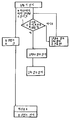
제2도는 그 플로우 차아트이다.2 is the flow chart.
* 도면의 주요부분에 대한 부호의 설명* Explanation of symbols for main parts of the drawings
1 : 가열원 경로 2 : 유량 제어 밸브1: heating source path 2: flow control valve
3,4,5 : 용액 경로 6,7,8 : 냉매 경로3,4,5:
9 : 냉수 경로 10 : 부하9: cold water path 10: load
11 : 냉수 펌프 12 : 냉각수 경로11: cold water pump 12: cooling water path
13 : 냉각수 펌프 14 : 냉각탑13: cooling water pump 14: cooling tower
15 : 용량 제어 장치 16 : 온도 검출기15
18 : 제어 장치 21 : 온도 검출기18: control unit 21: temperature detector
22 : 시한 기구 23 : 온도 검출기22: time mechanism 23: temperature detector
24 : 개도(開度) 검출기 25 : 압력 검출기24: Opening degree detector 25: Pressure detector
A : 흡수기 C : 응축기A: Absorber C: Condenser
E : 증발기 GH : 고온 발생기E: Evaporator GH: High Temperature Generator
GL : 저온 발생기 XH : 고온 열교환기GL: Low Temperature Generator XH: High Temperature Heat Exchanger
XL : 저온 열교환기 SP : 용액 펌프XL: low temperature heat exchanger SP: solution pump
RP : 냉매 펌프 V : 감압 밸브RP: refrigerant pump V: pressure reducing valve
본 발명은 운전 정지시의 조작을 행하는 제어 장치를 갖는 2중 효용 흡수 냉동기에 관한 것이다.The present invention relates to a dual-effect absorption chiller having a control device that performs an operation at the time of stopping operation.
종래의 흡수 냉동기에 있어서는 운전 정지시에, 용액의 결정화를 방지하기 위하여 발생기 가열원의 제어 밸브를 닫아서 냉동기의 운전을 정지시킨 후에도 용액 펌프는 운전을 계속하여, 용액 경로중의 농도를 균일화하는 희석 운전을 한후 용액 펌프를 정지하고 있는 것이지만, 냉각수 펌프도 용액 펌프와 함께 운전을 계속하고 용액 펌프의 정지와 함께 정지하도록 되어 있었다.In the conventional absorption refrigerator, the solution pump continues to operate even after stopping the operation of the refrigerator by closing the control valve of the generator heating source in order to prevent the crystallization of the solution at the time of stopping operation, and diluting to uniform the concentration in the solution path. Although the solution pump was stopped after the operation, the cooling water pump was also supposed to continue operation with the solution pump and to stop with the stop of the solution pump.
그런데 통상은 용액 펌프의 출력(예컨데 1~2kw)에 비하여 냉각수 펌프의 출력은 크고(예컨데 6~10kw), 냉각수 펌프를 필요 이상으로 운전하기 때문에 동력의 손실을 초래하였다.In general, however, the output of the cooling water pump is larger than the output of the solution pump (for example, 1 to 2 kw) (for example, 6 to 10 kw), and the cooling water pump is operated more than necessary, resulting in loss of power.
또, 냉각수의 통수(通水)를 필요 이상으로 행하면 고온 발생기의 내압이 저하하여 용액의 순환이 행해지기 어렵게 되어, 농도의 균일화가 충분히 이루어지지 않아 결정(結晶)을 초래할 염려가 있었다.Moreover, if the water flow of the cooling water is carried out more than necessary, the internal pressure of the high-temperature generator is lowered and the circulation of the solution is difficult to be performed, and there is a fear that the uniformity of the concentration is not sufficiently achieved, resulting in crystallization.
이와같은 저장을 피하기 위하여, 냉동기의 정지시에 냉각수 펌프를 즉시 정지시키면 냉각되지 않은 고온인 채로의 스프레이 용액이 뿌려져서 냉각수 튜우브내의 냉각수의 온도가 상승하여 튜우브의 열팽창으로 기인하는 과대응력에 의해 튜우브가 손상되거나, 재기동(再起動)시에 냉각 탑내의 플라스틱의 충전재를 손상시킨다고 하는 지장을 초래하였다.In order to avoid such storage, if the cooling water pump is stopped immediately when the freezer is stopped, the spray solution will be sprayed with the uncooled high temperature, causing the temperature of the cooling water in the cooling water tub to rise, thereby overheating due to the thermal expansion of the tub. This caused the trouble that the tub was damaged or the plastic filler in the cooling tower was damaged upon restart.
본 발명은 종래의 것의 상기와 같은 문제점을 해결하여, 동력의 손실을 경검하고 용액의 희석을 촉진하여, 열응력으로 인한 튜우브의 손상을 방지하고, 또한 제기동시에 냉각탑내의 충전재를 손상시키는 일이 없는 2중 효용 흡수 냉동기를 제공하는 것을 목적으로 하는 것이다.The present invention solves the above-mentioned problems of the conventional ones, to prevent the loss of power and to promote the dilution of the solution, to prevent the damage of the tubing due to thermal stress, and also to damage the filler in the cooling tower at the same time. It is an object of the present invention to provide a dual effect absorption freezer.
본 발명은 상기 문제점을 해결하기 위한 수단으로서, 증발기, 흡수기, 고온 발생기, 저온 발생기, 응축기, 이들의 기기를 접속하는 용액 경로, 냉매 경로, 이들의 경로에 설치된 용액 펌프, 냉매 펌프, 상기 흡수기 및 응축기에 통해져 있는 냉각수 경로, 이 냉각수 경로에 설치된 냉각수 펌프, 상기 증발기에 통해져 있는 냉수 경로, 이 냉수 경로에 설치된 냉수 펌프를 구비하고, 냉동기 운전정지후 소정의 설정시간후에, 상기 냉각수 펌프의 운전을 정지시키는 신호를 발생하는 시한 기구를 가지는 제2중 효용 흡수 냉동기에 있어서, 냉동기의 운전 정지전의 부하 상태를 검출하는 부하 검출기와, 이 부하 검출기에 의해서 검출된 냉동기 운전 정지전의 운전중의 부하 상태에 응해서, 부하가 클때에는 시간을 길게하고, 부하가 짧을때는 시간을 짧게하도록 소정의 설정 기간을 선택하는 제어 기구를 구비한 것을 특징으로 하는 2중 효용 흡수 냉동기를 제공하고자 하는 것이다.The present invention is a means for solving the above problems, evaporator, absorber, high temperature generator, low temperature generator, condenser, solution path for connecting their equipment, refrigerant path, solution pump installed in the path, refrigerant pump, the absorber and And a cooling water pump installed in the cooling water path, a cooling water pump installed in the cooling water path, a cold water path passing through the evaporator, and a cold water pump installed in the cooling water path. In a second-effect absorption chiller having a time limit mechanism for generating a signal for stopping operation, a load detector for detecting a load state before stopping operation of the refrigerator and a load during operation before stopping the freezer operation detected by the load detector. Depending on the condition, lengthen the time when the load is large, and shorten the time when the load is short. Intended to provide the utility of the
본 발명에 의해 흡수 냉동기 정지시에 냉각수 펌프를 즉시 정지시키는 것은 아니고, 정지전의 부하 상태에 응해서 잠시 운전을 속행시킴으로써 냉각수의 순환이 계속행해진다. 용액 펌프는 희석 운전을 위해 계속 운전되고, 용액의 순환이 행해지고 있으나, 발생기에서의 가열은 이미 정지되어 있으므로 냉각수에 의해 냉각되어서 용액 온도는 점차로 저하하고 냉각수 온도도 점차로 저하한다.According to the present invention, the cooling water pump is not immediately stopped at the time of stopping the absorption chiller, but the circulation of the cooling water is continued by continuing the operation for a while in response to the load state before stopping. The solution pump continues to run for the dilution operation, and the circulation of the solution is performed, but since the heating in the generator is already stopped, the solution pump is cooled by the cooling water so that the solution temperature gradually decreases and the cooling water temperature also gradually decreases.
냉각탑에 사용되는 충전재에는 예컨대 경질 염화 비닐(PVC) 등이 사용되고, 그들의 실용적인 내열 한도는 대개 60~80℃ 정도이다.For example, hard vinyl chloride (PVC) or the like is used for the filler used in the cooling tower, and their practical heat resistance limit is usually about 60 to 80 ° C.
따라서 냉동기의 운전 정지후 냉각수의 온도가 점차로 저하하며, 냉각수의 통수를 정지하여 정류 상태로 되는 냉각수 튜우브내의 냉각수가 비교적 고온의 용액(이미 어느 정도 온도 강하하고 있음)이 뿌려지더라도 상기한 내열한도에 도달하지 않을 정도(예컨데 25~30℃) 이하로 되었을 때에 냉각수 펌프를 정지시키면 되나, 이 냉각수 온도의 저하 상태는 정지 시점 혹은 그 직전의 부하 상태에 관계한다.Therefore, the temperature of the cooling water gradually decreases after the operation of the refrigerator is stopped, and even if a relatively hot solution (already dropping in temperature) is sprayed in the cooling water tub that stops the passage of the cooling water and becomes rectified, the heat resistance described above. The cooling water pump may be stopped when the limit is not reached (for example, 25 to 30 ° C.) or lower, but the lowering state of the cooling water temperature is related to the stopping state or the load state immediately before it.
즉, 정지 시점에 있어서 고부하로 운전하고 있는 경우에는 발생기내의 압력이 높고 용액 온도도 높으며, 따라서 흡수기로의 복귀 용액의 온도도 높아지고 운전 정지후의 냉각수의 온도 저하의 속도도 지연된다.That is, when operating under high load at the time of stopping, the pressure in the generator is high and the solution temperature is high, so that the temperature of the return solution to the absorber is high and the rate of temperature drop of the cooling water after the operation stops is also delayed.
그 때문에, 냉동기의 운전 정지후, 냉각수 온도가 소정의 하용 온도에까지 저하하는데 요하는 시간은 고부하 운전후의 경우는 길고 저부하운전후의 경우는 짧다.Therefore, after stopping operation of the refrigerator, the time required for the cooling water temperature to drop to a predetermined unloading temperature is long after high load operation and short after low load operation.
운전 정지시점 또는 그 직전(직전의 시점 혹은 정지시의 10분 정도전부터 정지시까지의 평균)의 부하상태를 용액의 온도등에 따라 검출하고 한편, 운전 정지시부터 소정의 설정 시간후에 냉각수 펌프를 정지시키는 시한 기구를 설치하고, 이 시한 기구의 설정 시간을 미리 검출한 부하 상태에 응해서 선택하고, 냉각수 온도가 소정의 허용온도 이하로 되는 시점 이후에 냉각수 펌프를 정지시키도록 한다.The load state at or near the operation stop (or just before or the average of about 10 minutes before the stop to the stop) is detected according to the temperature of the solution, and the coolant pump is stopped after the predetermined time from the operation stop. A time limit mechanism is provided, and the set time of the time limit mechanism is selected in response to a pre-detected load state, and the coolant pump is stopped after the point at which the coolant temperature becomes below a predetermined allowable temperature.
본 발명에서는, 이와같은 시한 기구의 설정 시간을 정지 시점 혹은 그 이전의 부하 상태에 따라 선택하여 냉각수 펌프를 정지하도록 함으로써 냉각수의 통수 정지후 비교적 고온(이미 어느정도 온도 강하하고 있음)의 용액이 뿌려지더라도 튜우브내에 정류되어 있는 냉각수가 상기 한도의 60~80℃에 달하는 일이 없고 튜우브의 열팽창으로 인한 손상도 방지하고, 그후 냉동기를 재기동시키더라고 냉각탑에는 충분히 저온으로된 냉각수가 보내지므로 충전재를 손상시키는 일이 없다. 더욱이, 냉각수 펌프를 필요이상으로 오래 운전하여 동력의 손실을 초래하거나, 고온 발생기내 압력을 지나치게 저하시켜서 희석 운전에 지장을 가져오는 일도 없다.In the present invention, the setting time of such a time mechanism is selected according to the stopping time or the load state prior to this, so that the cooling water pump is stopped so that a solution of relatively high temperature (already lowering temperature) is sprayed after the cooling water is stopped. Even though the cooling water rectified in the tub does not reach 60 ~ 80 ℃ of the above limit, it also prevents damage due to the thermal expansion of the tub, and after the machine is restarted, the cooling water is sent to the cooling tower at a sufficiently low temperature. There is no damage. Moreover, the cooling water pump is operated for longer than necessary to cause loss of power, or excessively lower the pressure in the high temperature generator, thus preventing the dilution operation.
또한, 부하 상태를 검출하는 부하 검출기로서, 용액의 온도를 검출하는 온도 검출기를 사용할 경우에는 용액 경로중의 되도록 고온, 고압의 부부(전온 발생기(GL)의 압력정도 이상의 부분, 예컨대 고온 발생기(GH)내, 고온 발생기(GH) 출구 등)에 있어서의 온도를 검출하는 것이 바람직하다. 그외에 부하 검출기로서는 고온 발생기(GH)의 가열량을 검출하는 것으로서, 가열 원류채(증기,열수 혹은 직화식의 경우의 연료가스, 연료유)의 유량 검출기, 또는 유량 제어밸브의 개도 검출기를 사용하여도 좋다. 또, 부하 검출기로서는 고온 발생기(GH)내의 압력 또는 포화 온도를 검축하는 압력 검출기, 온도 검출기를 사용하여도 좋다. 또 이상의 온도, 압력에 관련되어 있는 냉각수 온도를 검출하는 온도 검출기를 사용하여도 좋다.In addition, in the case of using a temperature detector that detects a temperature of a solution as a load detector that detects a load state, a portion of a high temperature or high pressure (part above the pressure level of the electric temperature generator GL, for example, the high temperature generator GH) in the solution path so that ), The temperature in the high temperature generator (GH) outlet, etc.) is preferably detected. In addition, the load detector detects the heating amount of the high-temperature generator GH, and uses a flow rate detector of a heating source stream (steam, hot water or fuel gas or fuel oil in the case of a direct fire) or an opening degree detector of a flow control valve. You may also do it. As the load detector, a pressure detector and a temperature detector for detecting the pressure or the saturation temperature in the high temperature generator GH may be used. Moreover, you may use the temperature detector which detects the cooling water temperature related to the above temperature and pressure.
본 발명의 실시예에 대하여 도면을 사용하여 설명한다.Embodiments of the present invention will be described with reference to the drawings.
제1도에 있어서 A는 흡수기, E는 증발기, GH는 고온 발생기, GL은 저온 발생기, C는 응축기, XH는 고온 용액 열 교환기, XL은 저온 용액 열교환기, SP는 용액 펌프, RP는 냉매 펌프, V는 감압 밸브이다.In Figure 1, A is an absorber, E is an evaporator, GH is a high temperature generator, GL is a low temperature generator, C is a condenser, XH is a high temperature solution heat exchanger, XL is a low temperature solution heat exchanger, SP is a solution pump, RP is a refrigerant pump , V is a pressure reducing valve.
이들의 기기 사이를 용액 경로(3,4,5) 냉매 경로(6,7,8)가 접속시키고, 흡수 용액 및 냉매가 순환한다.The
1은 증기등의 가열 원류체가 흐르는 가열원 경로이며, 유량제어밸브(2)에 의해 가열원류체의 유량을 제어하여 흡수 냉동기의 용량을 제어하도록 되어 있다.1 is a heating source path through which a heating source such as steam flows, and the flow
9는 냉수 경로이며, 부하(10)와 증발기(E)와의 사이에 냉수 펌프(11)에 의해 냉수를 순환시키도록 되어 있다.9 is a cold water path | route, and cold water is circulated by the
12는 냉각수 경로이며, 냉각수 펌프(13)에 의해 냉각탑(14), 흡수기(A), 응축기(C)를 순환하도록 되어있다.12 is a cooling water path, and the
15는 용량 제어 장치이며, 냉수 출구 온도를 검출하는 온도 검출기(16)로부터의 냉수 온도 신호를 받아, 냉수 온도가 일정하게 되도록 유량 제어 밸브(2)를 조작하도록 되어 있다.15 is a capacity control device, and receives the cold water temperature signal from the
18은 제어 장치이며 냉동기의 운전 정지시부터, 시한 기구(22)로부터 주어지는 설정 시간 경과후 냉각수 펌프(13)를 정지하는 신호가 발하여지도록 되어 있다. 그리하여, 시한 기구(22)에서의 설정 시간은 부하 검출기인 고온 발생기(GH)내의 용액 온도를 검출하는 온도 검출기(23)에 의해 검출된 운전 정지시 혹은 그 직전의 용액 온도에 따라 선택된다.18 is a control apparatus, and the signal which stops the
부하 검출기로서는 고온 발생기(GH)의 출구에서의 용액 온도로 검출하는 온도 검출기(21)를 사용하여도 좋고, 가열량에 근거하여 부하를 검출하기 위하여 가열원류체의 유량을 검출하는 유량 검출기나, 그 유량 제어 밸브(2)의 개방 정도를 검출하는 개도 검출기(24)를 사용혀도 좋고, 고온 발생(GH)의 내압을 검출하는 압력 검출기(25)를 사용하여도 되고, 또 이들의 온도, 압력에 관련하는 냉각수 온도를 검출하는 온도 검출기를 사용하여도 좋다.As the load detector, a
제2도는 운전 정지시의 프로우 차아트이다.2 shows the procha art at the time of stopping.
본 발명에 의해 흡수 냉동기가 운전을 정지함에 있어, 불필요한 동력의 손실을 방지하는 동시에 용액의 희석을 촉진하여 열응력으로 인한 흡수기의 냉각수 튜우브의 손상을 방지하고, 또한 재기동에 있어 냉각탑의 충전재의 손상을 초래할 염려가 없는 2중 효용 흡수냉동기를 제공할 수 있어, 실용상 극히 큰 효과를 얻는다.According to the present invention, when the absorption chiller stops operation, it prevents unnecessary power loss and promotes dilution of the solution to prevent damage to the cooling water tubing of the absorber due to thermal stress, and also to restart the filling material of the cooling tower in restarting. It is possible to provide a dual-effect absorption chiller which does not cause any damage, thereby obtaining a very large practical effect.
Claims (5)
Applications Claiming Priority (3)
| Application Number | Priority Date | Filing Date | Title |
|---|---|---|---|
| JP61-6254 | 1986-01-17 | ||
| JP61006254A JPS62166272A (en) | 1986-01-17 | 1986-01-17 | Double-effect absorption refrigerator |
| JP2654 | 1986-01-17 |
Publications (2)
| Publication Number | Publication Date |
|---|---|
| KR870007409A KR870007409A (en) | 1987-08-19 |
| KR960002565B1 true KR960002565B1 (en) | 1996-02-22 |
Family
ID=11633347
Family Applications (1)
| Application Number | Title | Priority Date | Filing Date |
|---|---|---|---|
| KR1019870000317A KR960002565B1 (en) | 1986-01-17 | 1987-01-16 | Double effective absorption refrigerator |
Country Status (2)
| Country | Link |
|---|---|
| JP (1) | JPS62166272A (en) |
| KR (1) | KR960002565B1 (en) |
Families Citing this family (4)
| Publication number | Priority date | Publication date | Assignee | Title |
|---|---|---|---|---|
| JP2765913B2 (en) * | 1989-02-14 | 1998-06-18 | 三洋電機株式会社 | Absorption refrigerator |
| JPH10325636A (en) * | 1997-05-22 | 1998-12-08 | Rinnai Corp | Absorption type air-conditioning device |
| JPH1183229A (en) * | 1997-09-09 | 1999-03-26 | Mitsubishi Heavy Ind Ltd | Device for stopping operation of absorption refrigerating machine |
| KR100337395B1 (en) * | 1999-07-20 | 2002-05-21 | 이동수 | Apparatus for sterilizing vacuum pack |
Family Cites Families (2)
| Publication number | Priority date | Publication date | Assignee | Title |
|---|---|---|---|---|
| JPS5222142A (en) * | 1975-08-13 | 1977-02-19 | Sanenerugii Kk | Water heater by solar heat |
| JPS6021719U (en) * | 1983-07-21 | 1985-02-14 | 石渡 裕子 | glasses |
-
1986
- 1986-01-17 JP JP61006254A patent/JPS62166272A/en active Granted
-
1987
- 1987-01-16 KR KR1019870000317A patent/KR960002565B1/en not_active IP Right Cessation
Also Published As
| Publication number | Publication date |
|---|---|
| KR870007409A (en) | 1987-08-19 |
| JPS62166272A (en) | 1987-07-22 |
| JPH0478903B2 (en) | 1992-12-14 |
Similar Documents
| Publication | Publication Date | Title |
|---|---|---|
| KR960008228A (en) | Absorption Chiller | |
| KR920003906B1 (en) | Absorption system hot and cold water supply apparatus | |
| JPH0996456A (en) | Control method and control device for absorption refrigerator | |
| KR960002565B1 (en) | Double effective absorption refrigerator | |
| US5749244A (en) | Absorption type refrigerator | |
| KR860002042B1 (en) | Control method of absorption type cold and warm water system | |
| KR100193333B1 (en) | Absorption Chiller | |
| JP3241550B2 (en) | Double effect absorption chiller / heater | |
| KR100443713B1 (en) | Absorption Chiller | |
| US3363674A (en) | Absorption refrigeration apparatus and methods | |
| JP3787744B2 (en) | Operation control method and operation control device for lithium bromide absorption refrigerator | |
| JPH05248726A (en) | Absorption refrigerating machine | |
| JPH05113266A (en) | Controller of absorption refrigerating machine | |
| JP3146373B2 (en) | Solution flow control method for absorption chiller / heater | |
| JP2939460B1 (en) | Absorption refrigerator and method of controlling capacity of absorption refrigerator | |
| JPH0447227B2 (en) | ||
| JPH08226722A (en) | Operation stopping method of absorption refrigerating machine | |
| JP2981560B2 (en) | Absorption chiller / heater with cooling / heating switching function | |
| JP3969527B2 (en) | Safety method for flue gas charging type absorption chiller / heater | |
| JP2940787B2 (en) | Double effect absorption refrigerator | |
| JP2744034B2 (en) | Absorption refrigerator | |
| JPS5944498B2 (en) | Exhaust heat utilization equipment | |
| JP2858931B2 (en) | Control device for absorption refrigerator | |
| JPH04151470A (en) | Control device for absorption type cold-hot water heater | |
| JP3412795B2 (en) | Double effect absorption chiller / heater |
Legal Events
| Date | Code | Title | Description |
|---|---|---|---|
| A201 | Request for examination | ||
| E902 | Notification of reason for refusal | ||
| G160 | Decision to publish patent application | ||
| E701 | Decision to grant or registration of patent right | ||
| GRNT | Written decision to grant | ||
| FPAY | Annual fee payment |
Payment date: 20060203 Year of fee payment: 11 |
|
| EXPY | Expiration of term |