KR950003554B1 - High-rat stand - Google Patents
High-rat stand Download PDFInfo
- Publication number
- KR950003554B1 KR950003554B1 KR1019890011947A KR890011947A KR950003554B1 KR 950003554 B1 KR950003554 B1 KR 950003554B1 KR 1019890011947 A KR1019890011947 A KR 1019890011947A KR 890011947 A KR890011947 A KR 890011947A KR 950003554 B1 KR950003554 B1 KR 950003554B1
- Authority
- KR
- South Korea
- Prior art keywords
- connection point
- rotating member
- wheel
- shaft
- hat stand
- Prior art date
Links
Images


Classifications
-
- G—PHYSICS
- G10—MUSICAL INSTRUMENTS; ACOUSTICS
- G10G—REPRESENTATION OF MUSIC; RECORDING MUSIC IN NOTATION FORM; ACCESSORIES FOR MUSIC OR MUSICAL INSTRUMENTS NOT OTHERWISE PROVIDED FOR, e.g. SUPPORTS
- G10G7/00—Other auxiliary devices or accessories, e.g. conductors' batons or separate holders for resin or strings
-
- G—PHYSICS
- G10—MUSICAL INSTRUMENTS; ACOUSTICS
- G10D—STRINGED MUSICAL INSTRUMENTS; WIND MUSICAL INSTRUMENTS; ACCORDIONS OR CONCERTINAS; PERCUSSION MUSICAL INSTRUMENTS; AEOLIAN HARPS; SINGING-FLAME MUSICAL INSTRUMENTS; MUSICAL INSTRUMENTS NOT OTHERWISE PROVIDED FOR
- G10D13/00—Percussion musical instruments; Details or accessories therefor
- G10D13/01—General design of percussion musical instruments
- G10D13/06—Castanets, cymbals, triangles, tambourines without drumheads or other single-toned percussion musical instruments
- G10D13/063—Cymbals
- G10D13/065—Hi-hats
Landscapes
- Physics & Mathematics (AREA)
- Engineering & Computer Science (AREA)
- Acoustics & Sound (AREA)
- Multimedia (AREA)
- Auxiliary Devices For Music (AREA)
- Orthopedics, Nursing, And Contraception (AREA)
- Mechanical Control Devices (AREA)
Abstract
내용 없음.No content.
Description
제 1 도는 본 발명의 높은 햇 스탠드(hat stand)의 첫번째 실시예의 수직단면도.1 is a vertical sectional view of a first embodiment of the high hat stand of the present invention.
제 2 도는 높은 햇 스탠드의 두번째 실시예의 부분 단면도.2 is a partial cross-sectional view of a second embodiment of a high hat stand.
제 3 도는 높은 햇 스탠드의 세번째 실시예의 동일 구조의 단면도.3 is a sectional view of the same structure of the third embodiment of the high hat stand.
제 4 도는 작동로드(rod)와 페달에 대한 레버아암(lever arm)을 휠(wheel)의 반경보다는 오히려 레버로서 도시한 것이나, 작동 윈리가 동일한 햇 스탠드의 네번째 실시예의 단면도.4 shows a lever arm for an actuating rod and a pedal as a lever rather than a radius of a wheel, but in cross section of a fourth embodiment of a hat stand with the same actuating winry.
제5a도 내지 제5d도는 본 발명의 작동 원리도.5a to 5d are operational principle diagrams of the present invention.
제 6 도는 본 발명에 의한 높은 햇 스탠드의 작용을 나타내는 개략도.6 is a schematic view showing the action of a high hat stand according to the present invention.
제7a도 내지 제7d도는 본 발명의 다양한 기능을 도시한 개략도.7A-7D are schematic diagrams illustrating various functions of the present invention.
제 8 도는 제8a도와 제8b도에 그래픽된 상태의 묘사도.8 is a depiction of the state graphically depicted in FIGS. 8a and 8b.
제8a도와 제8b도는 본 발명과, 종래의 높은 햇 스탠드의 실시예 사이의 비교도.8A and 8B show a comparison between the present invention and an embodiment of a conventional high hat stand.
제9a도와 제9b도는 본 발명에 의한 심벌(symbal) 작동로드의 기능을 도시한 개략도.9A and 9B are schematic diagrams showing the function of a symbol actuation rod according to the present invention.
제10도는 높은 햇 스탠드의 다섯번째 실시예의 단면도.10 is a sectional view of a fifth embodiment of a high hat stand.
제11도는 본 발명의 여섯번째 실시예의 단면도.11 is a sectional view of a sixth embodiment of the present invention.
제12a도의 제12b도의 제10도와 제11도의 회전부재의 작동원리를 설명하는 개략도.Fig. 12A is a schematic view for explaining the principle of operation of the rotating member of Figs. 10 and 11 of Fig. 12B of Fig. 12A.
제13a도와 제13b도는 제10도와 제11도의 작동원리를 다시 나타낸 개략도.13A and 13B are schematic diagrams showing the operating principle of FIGS. 10 and 11 again.
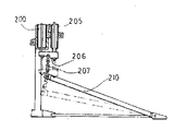
제14도는 종래의 높은 햇 스탠드의 단면도.14 is a cross-sectional view of a conventional high hat stand.
본 발명은 페달에 의해 상, 하로 움직이는 심벌 작동로드를 포함하는 높은 햇 스탠드에 관한 것이다.The present invention relates to a high hat stand comprising a cymbal actuating rod moving up and down by a pedal.
높은 햇 스탠드는 고정 하부심벌과 하부 심벌위에 이와 상호작용하는 가동 상부심벌을 갖는다. 가동 상부심벌은 스탠드의 하부에 연결된 페달의 운동에 의하여 상하로 움직이는 심벌에 대한 작동로드의 상, 하 운동에 의해 하부심벌에 맞닫도록 아래로 움직이고, 하부심벌로 부터 떨어져 위로 움직인다. 상부심벌은 통상작동로드위나 가까이에 연결된 스프링에 의해 하부심벌로 부터 떨어져 밀고나가게 된다. 연주자는 탄성력을 극복하도록 페달을 밟아 심벌들을 함께 이동시킨다. 높은 햇 스탠드에 있어서, 연주자의 음악연주를 정확히 표현하기 위하여 가동심벌의 작동의 고속화의 정확도 즉, 높은 응답성이 요구된다. 기구적으로는, 이 응답성은 페달이 가볍게 밟아지고 본래 심벌들의 분리된 위치로 빠르게 복귀된다는 것으로 부터 얻어진다. 작동로드는 스프링에 의해 계속적으로 위쪽으로 치우치게 되기 때문에, 페달을 가볍게 밟기 위해서는 스프링을 약하게 하는 것이 통상 필요하다. 그러나, 페달이 빠르게 복귀되게 하기 위하여는 강한 스프링이 필요한다. 이런 모순된 조건은 본 발명에 의해 충족된다. 더우기, 가동 심벌의 미묘한 개페를 허용하는 장치가 요구되고, 또는 미묘한 페달조작에 의해 상호 견고하게 닫혀진 심벌들을 약간 열리거나 닫히게 할수 있는 기구가 요구된다.The high hat stand has a fixed lower symbol and a movable upper symbol which interacts with it on the lower symbol. The movable upper symbol is moved downward to be in contact with the lower symbol by the up and down movement of the working rod with respect to the cymbal moving up and down by the movement of a pedal connected to the lower part of the stand, and moves up away from the lower symbol. The upper symbol is pushed away from the lower symbol by a spring connected to or near the normal operating rod. The player presses the pedal to move the cymbals together to overcome the elastic force. In the high hat stand, the accuracy of speeding up the operation of the movable symbol, that is, the high responsiveness, is required to accurately express the music performance of the performer. Mechanically, this responsiveness is obtained from the pedal being lightly pressed and quickly returning to the original position of the symbols. Since the actuating rod is continuously biased upward by the spring, it is usually necessary to weaken the spring in order to lightly press the pedal. However, a strong spring is needed to allow the pedal to return quickly. Such contradictory conditions are met by the present invention. Moreover, there is a need for a device that allows subtle opening of movable symbols, or a mechanism for slightly opening or closing symbols that are tightly closed to each other by subtle pedal operation.
공지된 높은 햇 스탠드에 있어서, 제14도에 도시된 바와 같이, 심벌 작동로드 200은 210과 직접 연결된다. 이것은 페달 210의 작동력을 심벌 작동로드 200에 작용하는 작동력과 같게하도록 한다. 더구나, 페달 210은 밟기 위하여는 스프링 장치 205의 스프링 압력과 동일한 힘이 필요하다. 제14도에서, 체인 207은 스프링 장치의 스프링과 작동로드를 결합하는 연결부 206을 페달 210과 연결한다.In the known high hat stand, as shown in FIG. 14, the
알려진 직접 연결 구조들은 극히 장식용인 것들로써 기본요구 조건의 만족에 대하여 개선된 것이 아니며, 스프링의 강도 또는 저항의 크기의 차이에 의한 연주의 감상을 변화시키도록 고안된 것이다.Known direct connection structures are extremely decorative and are not an improvement to the satisfaction of the basic requirements, but are designed to change the appreciation of the performance due to the difference in the strength of the spring or the magnitude of the resistance.
실험을 통하여, 본 발명자들은 페달과 심벌 작동로드가 상호 직접적으로 연결되어 있는 한, 상술된 요건을 충족할 수 없음에 주목하였다. 그 대신에, 페달과 심벌 작동로드는 서로다른 레버 작동 원리를 이용한 회전부재에 의하여 연결되어야 함을 알았다.Through experiments, the inventors have noted that as long as the pedal and symbol actuation rod are directly connected to each other, the above-mentioned requirements cannot be met. Instead, it was found that the pedal and the cymbal actuation rods should be connected by rotating members using different lever actuation principles.
본 발명의 첫번째 목적은 응답성이 좋은 높은 햇 스탠드를 제공하는 것이다.The first object of the present invention is to provide a high hat stand with good responsiveness.
다른 목적은 페달을 적은 힘으로 밟을 수 있는 스탠드를 제공하기 위한 것이다.Another object is to provide a stand on which the pedal can be stepped with little force.
또 다른 목적은 페달의 복귀가 빠른 스탠드를 제공하기 위한 것이다.Another object is to provide a stand with a quick return of the pedal.
또 다른 목적은 가동 심벌을 꽉 누를수가 있고, 더우기 미묘한 페달 조작이 가능한 스탠드를 제공하기 위한 것이다.Another object is to provide a stand that can press the movable symbol tightly, furthermore allowing for subtle pedal operation.
또 다른 목적은 레버의 원리를 이용하여 높은 햇 스탠드를 작동시키기 위한 스탠드를 제공하기 위한 것이다.Another object is to provide a stand for operating a high hat stand using the principle of a lever.
더우기, 본 발명은 이들 목적으로서, 심벌 작동로드의 직선 또는 축방향 운동을 제공하고, 로드의 유연한 운동과 심벌의 유연작동을 확보하는 높은 햇 스탠드를 제공한다.Furthermore, the present invention provides for these purposes a high hat stand which provides a straight or axial movement of the symbol actuation rod and ensures the flexible movement of the rod and the flex actuation of the symbol.
본 발명에서, 심벌 작동로드는 페달의 움직임에 의하여, 상, 하로 움직인다. 로드와 페달은 공동 회전 샤프트(shaft)에 끼워진 각각의 회전부재에 의하여 연결된다. 샤프트의 회전축에서 심벌 작동로드 연결점까지의 거리(Y)는 샤프트의 회전축에서 심벌 작동로드 연결점까지의 거리(Y)는 샤프트의 회전축에서 페달 연결점까지의 거리(X)보다 작게 설정된다.In the present invention, the symbol operation rod moves up and down by the movement of the pedal. The rod and the pedal are connected by respective rotating members fitted to the common rotating shaft. The distance Y from the axis of rotation of the shaft to the symbol actuation rod connection point is set smaller than the distance X from the axis of rotation of the shaft to the symbol actuation rod connection point than the distance X from the axis of rotation of the shaft to the pedal connection point.
이것은 본 발명에 따라 적당하게 다른 반경을 갖는 2개의 회전부재, 즉 회전축으로부터 다른 거리에 그의 연결점을 가지는 각 회전부재를 구비함으로써 성취된다. 하나 또는 두개의 회전부재는 회전부재 축 주위를 회전시키도록 한끝에 부착되고, 연결수단에 의하여 레버의 다른 하나의 회전끝의 연결점으로 부터 가동 심벌의 작동로드 또는 페달의 회전하는 끝에 구부리기 쉽게 연결되는 회동가능한 레버아암으로 이루어질수도 있다. 또 다른 방법은 하나 또는 두개의 회전부재는 회전축으로 부터 소저의 레버 아암 길이의 축 예를들면, 그의 주변밖의 연결점까지의 반경을 갖는 휠 또는 스프로킷(sprocket)으로 이루어질수도 있다. 체인과 같은 구부리기 쉬운 연결 수단은 가동 심벌의 작동로드 또는 페달의 회전하는 끝의 각각 하나에 접하여 휠을 부분적으로 풀고 휠주위에 감는다. 회전부재로서 소용되는 휠은 연결점이 항상 휠 주위의 일정 각도 위치에 있고 이 연결점은 연결수단이 휠을 접선방향으로 접하는 점이라는 이점을 갖는다.This is achieved according to the invention by having two rotating members with suitably different radii, ie each rotating member having its connection point at a different distance from the axis of rotation. One or two rotating members are attached at one end to rotate about the axis of the rotating member, and are connected by connecting means to bend easily from the connecting point of the other rotating end of the lever to the working rod of the movable symbol or the rotating end of the pedal. It may also consist of a rotatable lever arm. Alternatively, one or two rotating members may consist of wheels or sprockets having a radius from the axis of rotation to the axis of the lever arm length of the source, for example a connection point outside its periphery. Bendable connecting means such as chains partially unwind the wheel and wind it around the wheel in contact with each one of the actuating rod of the movable cymbal or the rotary end of the pedal. Wheels that serve as rotating members have the advantage that the connection points are always at a certain angular position around the wheel and this connection point is the point at which the connecting means tangentially contact the wheel.
더우기, 레버에 그의 구부리기 쉬운 연결부의 요동(swing)에 의해 작동로드에 가하는 압력을 감소시키기 위하여, 작동로드에 연결된 회전부재가 일단이 회전하는 레버인 경우에, 작동로드에 인가된 횡방향의 힘을 보상하기 위하여 회전부재 레버가 회동하면, 공통회전샤프트를 요통시키는 스태거(stagger)식 아암 또는 요동 아암의 요동끝에 의해 공통회전샤프트 또는 축이 유지된다.Furthermore, in order to reduce the pressure exerted on the actuating rod by swinging its bendable connection to the lever, the lateral force applied to the actuating rod, when the rotary member connected to the actuating rod is a lever that is rotated at one end. When the rotating member lever is rotated to compensate for this, the common rotating shaft or the shaft is held by the staggered arm or the swinging end of the swinging arm that makes the common rotating shaft back.
본 발명의 다른 목적과 특징들은 첨부된 도면에 의하여 발명의 바람직한 실시예들에 대한 다음의 설명으로 부터 명백히 표출된다.Other objects and features of the present invention are apparent from the following description of the preferred embodiments of the invention by the accompanying drawings.
높은 햇 스탠드의 구조에 대하여는 제 1 도의 첫번째 실시예에 의하여 설명한다. 높은 햇 스탠드 10의 상단에는, 위쪽으로 향한 고정 하부심벌 11과 아래쪽으로 향한 가동 상부심벌 12가 있다. 고정 하부심벌 11은 스탠드의 본체 파이프 13에 고정된다. 가동 상부심벌 12는 본체 파이프 13을 통하여 수직으로 움직이는 심벌 작동로드 15에 지지된다. 작동로드 15의 수직운동은 상부심벌을 고정 하부심벌 11로 부터 분리되거나 맞닫도록 하게 한다.The structure of the high hat stand will be described by the first embodiment of FIG. At the top of the high hat stand 10, there is a fixed
가동 상부심벌의 작동로드 15는 스프링 장치 30에 의해 심벌을 항시 위쪽으로 치우치게 한다. 스프링 장치 30은 본체 관형부 31을 포함한다. 조절캡(adjusting cap) 32는 본체 관형부 31의 상단에 나합된다. 코일 스프링 35는 본체 관형부 31의 하부의 하부 스프링수납재 36과 조절캡 32위의 상부 스프링수납부재 37사이에 팽창 또는 조절 자유롭게 유지되어 있다.The actuating
브레키드(bracket) 39는 스탠드의 본체 파이프 13상에 스프링 장치 30의 본체를 지지한다. 하부 스프링 수납부재 36아래의 로드부 36a는 횡방향으로 연장되는 연결부재 38에 의하여 가동심벌 작동로드 15와 연결되고, 작동로드 15에 항상 위를 향한 치우침을 부여한다. 교체배열로는, 도시되지 않은 스프링을 본체 파이프 13안쪽의 작동로드에 직접 감을수도 있다.The
본 발명에서, 심벌 작동로드 15와 페달 20은 페달 20에 의해 심벌 작동로드 15의 작동을 가능케하기 위하여, 회전축의 공동회전 샤프트를 갖는 공통장치를 공유하는 2개의 회전부재에 의해 연결된다. 각각의 회전부재에 있어서 작동로드 15에 대해 첫번째 연결부재를 수납하는 제 1 도의 휠 50의 주변에 회전축에서 첫번째 연결점까지의 거리는 페달에 대한 연결부재 61을 수납하는 제 1 도의 레버 60끝에 회전축에서 두번째 연결점까지의 거리보다 작게 설정된다. 특히 심벌 작동로드 15는 직경이 작은 휠 50, 연결부재 체인 51과 연결부재 38을 통하여 연결된다. 심벌 작동로드 15를 작동시키기 위한 체인 51은 스프로킷인 톱니모양의 휠50에 감겨진 링크(link) 체인이다. 휠위의 첫번째 연결점은 휠 50주위의 특정 각위치, 제 1 도의 약 90°위치에 있다. 체인 51은 휠 50에 접촉하다. 수직으로 회동가능한 페달 20의 회전하는 끝은 링크체인 61의 길이등과 같은 구부리기 쉬운 연결부재를 통하여 긴 레버 60의 외부 회전끝의 두번째 연결점에 연결된다.In the present invention, the
휠 50과 긴 레버 60은 공통 회전 샤프트 40을 갖고, 회전축 또는 지점(fulculum) 0로써 회전샤프트 40을 갖는 단일체로써 상호 작동한다. 회전샤프트 40은 페달 스탠드의 정면에 22위에 회동가능하게 지탱된다.The
직경이 작은 직경의 휠 50의 회전축 40에서 심벌 작동로드 연결수단 즉, 체인 51에 대한 연결점가지의 거리 또는 레버아암(Y)는 체인 51이 접선방향으로 분리되는 휠 50주위의 점과 40사이의 거리와 같고, 이는 휠 50의 반경이다. 거리 또는 길이(Y)는 긴레버 60의 회전샤프트 40에서 페달 연결수단 61에 대한 레버 60의 자유단의 두번째 연결점까지의 거리 또는 길이(X)보다 짧다. 이들 레버 아암들은 이하에 설명된 바와 같이 작동중에 중요한 것이다. 직경이 작은 휠 50위의 심벌 작동로드에 대한 첫번째 연결점은 힘점 또는 지점 J와 동등하다. 긴 레버 60의 경우에, 페달에 대한 두번째 연결점은 마찬가지로 힘점 Q와 동등하다. 작동로드와 페달에 인가된 힘의 크기는 그들 힘점의 위치의 반경 거리에 따라 변화한다.On the axis of rotation 40 of the
작동로드와 페달에 힘의 모멘트는 인가된 힘과 레버길이 또는 거리 사이의 관계를 갖는다. 예를들면, 회전샤프트(O)에서 두번째 페달 연결점(Q)까지의 거리 (X)가 1인경우, 회전샤프트(O)에서 첫번째 심벌 작동로드 연결점 j가지의 거리(Y)가 사실상 0.5와 0.7사이의 범위에 있는 장치를 사용하는 것이 쉽다. (Q)에서 페달 20에 인가되 것과 비교하면, 이것은 로드 15에 힘을 증가시키고, 이것은 점(Q)에 의해 이동된 해당하는 거리에 대해 로드 15의 이동거리를 감소시킨다.The moment of force on the actuating rod and the pedal has a relationship between the applied force and the lever length or distance. For example, if the distance (X) from the rotary shaft (O) to the second pedal connection point (Q) is 1, the distance (Y) of the first symbol operating rod connection point j at the rotary shaft (O) is in fact 0.5 and 0.7. It is easy to use the device in the range between. Compared to that applied to pedal 20 at (Q), this increases the force on
제 2 도는 한 회전부재가 심벌 작동로드 15의 연결된 샤프트 41위의 반경이 작은 휠 70으로 이루어지고 다른 한 회전부재가 페달과 연결된 샤프트 41위의 직경이 큰 휠 80으로 이루어진 다른 실시예를 도시한 것이다. 여기서, 또한, 샤프트 41에 고정되는 직경이 작은 휠 70과 직격이 큰 휠 80은 공통 회전샤프트 41 또는 O를 갖는 단일 장치로써 작동한다. 직경이 작은 휠 70은 가동심벌 작동로드 15를 작동시키기 위한 체인 71을 구비하고, 직경이 큰 휠 80은 페달의 자유단에 연결시키기 위한 체인 81을 구비한다. 제 2 도에서, 참조부호 J, Q, X 및 Y는 각각 작동로드 연결점, 페달연결점, 회전샤프트에서 작동 로드 연결점(O-Q)까지의 거리, 및 회전샤프트에서 페달 연결점(O-J)까지의 거리를 표시한 것이다. 요켠대, 제1도의 레버 60은 휠 70이 제 1 도에서 휠과 같이 작동하는 반면, 휠 80에 의해서 구성상, 기능상으로 대신한다.2 shows another embodiment in which one rotating member consists of a
제 3 도는 세번째 실시예를 도시한 것이다. 여기서 길이가 짧은 레버 90은 심벌 작동로드 15를 구동시키기 위한 회전부재로서 사용되고, 직경이 큰 휠 100은 페달에 의해 동작시키기 위한 회전부재로서 사용된다. 여기서 또한, 공통회전 샤프트 42에 고정되는 레버 90과 휠 100은 회전의 지점 O를 갖는 단일체로서 작동한다. 체인 91은 짧은 레버 90과 심벌 작동로드 15를 연결한다. 페달 20으로부터의 연결체인 101은 휠 100에 감겨진다. 체인 91과 101은 초기의 실시예로써, 레버 90과 휠 100위의 각 연결점에 부착된다.3 shows a third embodiment. Here, the
제 4 도는 네번째 실시예를 도시한 것이다. 여기서, 짧은 레버 110은 심벌 작동로드 15를 작동시키는 반면, 긴 레버 12은 페달 20에 의해 작동되며, 야 레버는 각각 회전부재들로써 사용된다. 공통 회전샤프트 43에 고정된 짧고, 긴 레버 110, 120은 회전에 대한 지점 0를 갖는 단일체로서 작동한다. 체인 111은 짧은 레버 110을 심벌 작동로드 15와 연결한다. 체인 121은 긴 레버 120을 페달 20과 연결한다. 체인 111과 121은 또한 레버 110과 120위의 각 연결점에 부착된다.4 shows a fourth embodiment. Here, the
제 1 도 내지 제 4 도의 실시예는 본 발명에 대한 레버들과 스프로킷 휠들의 기능의 동일과 대체를 설명한것이다. 그러나, 이하에 설명된 바와 같이, 특히 심벌 작동로드 작동시키기 위하여, 휠보다 레버를 사용하면 작동로드위의 응력을 최소화하기 위해 요동가능한 스태거식 아암을 필요로 한다.1 to 4 illustrate the same and alternative functions of the levers and sprocket wheels for the present invention. However, as described below, in particular to operate a symbol actuation rod, the use of a lever rather than a wheel necessitates a staggerable staggered arm to minimize stress on the actuation rod.
제5a도-제5d도는 첫번째-네번째 실시예들의 각각에 2개의 회전부재의 작동원리를 도시한 것이다. 제5a도는 제 1 도의 직경이 작은 휠 50과 긴레버 60을 도시한 것이고, 제5b도는 제 2 도의 직경이 작은 휠 70과 직경이 큰 휠 180을 도시한 것이고, 제5c도는 제 3 도의 짧은 레버 90과 직경이 큰 휠 100, 제5d도는 제 4 도의 짧은 레버 110과 긴레버 120을 도시한 것이다. 각 회전부재는 지점 또는 축 O, 작동로드 15에 레버아암을 설정하는 작용점 J와 페달에 레버아암을 결정하는 힘점 Q를 갖는다.5a-d show the operating principle of the two rotating members in each of the first-fourth embodiments. FIG. 5a shows the
휠과 레버가 각 실시예에 있어서 회전부재로서 대체할 수 있게 사용될수도 있기 때문에, 본 발명에 의한 높은 햇 스탠드의 작동원리를 나타내기 위하여 제 1 도에 설명된 직경이 작은 휠 50과 긴 레버 60의 실시예를 이하에 설명하고 제 6 도에 도시하였다. 아암의 길이(Y)에 의해 배가된 심벌 12를 잡아 내리는 힘(W)는 페달이 아암(X)의 길이에 의해 배가된(P)에 밟아지는 힘과 동일하다. 스프링 35의 치우침에 대하여 심벌(W)를 잡아내리는데 요구되는 힘 또는 페달이 (P)에 밟아지는 힘은 (X)와 비교하여 (Y)의 비율이 보다 작게됨에 따라, 즉 작용점 J가 지점 O에 접근함에 따라 보다 작거나 가볍게 할 수가 있다.Since the wheel and lever may be used as replacement members in each embodiment, the
한편, 설정된 거리(H)에 의해 심벌 12를 잡아내리는데 요구되는 페달 20의 작동거리(H)는 직경이 작은 휠 50과 긴레버 60의 (Y)대 (X)의 비율에 역비례한다. 즉, 페달의 스트로우트(stroke)는 작용점 J가 지점 O에 근접함에 따라 증가되어야 한다.On the other hand, the operating distance H of the pedal 20 required to lower the
보다 상세한 설명은 실제의 높은 햇 스탠드에 대한 제 7 도에 나타난다. 제7a도-제7d도는 회전부재의 (X) : (Y)길이 비율이 길이측정의 1 : 0.5단위로 설정되는 경우에, 다양한 기능을 개념상으로 도시한 것이다.A more detailed description is shown in FIG. 7 for the actual high hat stand. 7A to 7D conceptually show various functions when the (X) :( Y) length ratio of the rotating member is set to 1: 0.5 unit of length measurement.
이 예와 종래의 높은 햇 스탠드의 비교결과를 이하의 표 1에 표시하였다.The comparison result between this example and the conventional high hat stand is shown in Table 1 below.
[표 1]TABLE 1

제 7도a도에서, 심벌 작동로드 15에 인가되는 스프링 압력이 F로 표시되는 경우, 페달을 밟는데 요구되는 힘은 1/2F일 수 있다. 스프링 압력이 동일한 상태로 있는 경우에(표 1의 본 발명A의 경우), 본 발명이 종래 제품의 페달보다 작은 힘으로 밟을 수 있다는 것을 나타낸다. 그 결과, 종래보다 스프링함이 큰 작동로드 복귀 스프링을 사용할 수가 있다. 표 1 의 발명B에서, 스프링 압력이 종래 스탠드의 스프링에 대해 1.5배 만큼 큰 스크링을 사용하는 경우에, 높은 햇 스탠드 보다 작은 힘(3/4)으로 페달을 밟을 수 있다.In FIG. 7A, when the spring pressure applied to the
제7b도는 페달을 P힘으로 밟을때에 가동심벌에 2P힘을 인가하여 가동심벌이 고정심벌과 접촉할때 닫힌 상태를 도시한 것이다. 실제로, 심벌들은 스프링의(2F-F)의 힘으로 가해진다. 종래의 (P-F)의 힘과 비교할때, 심벌들의 견고한 닫힘상태가 성취될 수 있고, 이것에 의해서 보다 나은 연주를 위해 견고한 닫힘상태를 실현할 수가 있다.FIG. 7B shows the closed state when the movable symbol is in contact with the fixed symbol by applying a 2P force to the movable symbol when the pedal is pressed by the P force. In practice, the symbols are applied with the force of the spring (2F-F). Compared with the force of the conventional (P-F), a solid closed state of the symbols can be achieved, thereby realizing a solid closed state for better performance.
제7c도는 페달을 Smm거리만큼 이동할때, 심벌이 1/2Smm거리만큼 이동한 것을 도시한 것이다. 레버의 원리에 의해, 힘이 1/2만큼 크게될때, 거리는 2배만큼 크게 된다.FIG. 7C illustrates that when the pedal is moved by the distance Smm, the symbol is moved by the
위의 설명은 페달작동을 "가볍고 쉽게" 행할 수 있고 본 발명이 심벌을 닫힘상태로 유지한 상태를 미묘한 개폐의 훌륭한 연주 기술에 대해 아주 유용하다는 것을 나타낸 것이다.The above description shows that the pedal operation can be "light and easy" and that the present invention is very useful for a fine playing technique of subtle opening and closing while keeping the cymbal closed.
제7d도는 심벌 작동로드를 속도 V로 복귀할때 페달이 속도 2V로 복귀된다는 것을 도시한 것이다. 이 복귀상태를 연주자에게 있어 페달의 발판이 연주자의 발바닥에 부착되는 것처럼 보이게 한다. 이것은 연주자에게 즐거운 느낌을 주어 연주기술을 향상시킨다.FIG. 7d shows that the pedal returns to speed 2V when returning the symbol actuation rod to speed V. FIG. This return state makes it appear to the player that the footrest of the pedal is attached to the sole of the player. This gives the player a pleasant feeling and improves their playing skills.
제 8 도는 실제의 높은 햇 스탠드에 대해 측정된 결과를 그래프화 한것이고 작동로드 연결점(J)를 회전부재로 변화시킨 경우에, 제8a도에 페달스트로우크와 밟는 힘사이의 관계와 제8b도에 페달스트로우크와 가동심벌의 거리사이의 관계를 도시한 것이다.FIG. 8 is a graph of the measured results for the actual high hat stand, and the relationship between the pedal stroke and the stepping force in FIG. 8A and FIG. 8B when the actuating rod connection point J is changed to the rotating member. The relationship between the pedal stroke and the distance of the movable symbol is shown.
도시한 바와 같이, 파선은 X : Y가 6 : 4(길이 X가 1일때 Y는 0.67)인 경우를, 이점쇄선은 X : Y가 7 : 4(길이 X가 1일때 길이 X는 0.57)인 경우를, 일점쇄신은 X : Y가 8 : 4(길이 X가 1일때 길이 Y는 0.5)인 경우를 표시한 것이다. 실선은 작동로드와 페달을 직접 연결한 종래 제품을 표시한 것이다.As shown, the dashed line is the case where X: Y is 6: 4 (Y is 0.67 when length X is 1), and the dashed line is X: Y is 7: 4 (length X is 0.57 when length X is 1). In one case, the one-point print represents the case where X: Y is 8: 4 (the length Y is 0.5 when the length X is 1). The solid line represents a conventional product in which a working rod and a pedal are directly connected.
레버가 페달을 심벌 작동로드 사이의 연결용으로 사용되는 이 첫번째 실시예의 높은 햇 스탠드는 레버들에 대한 그 의존관계로부터 발생하는 우수한 효과를 갖는다.The high hat stand of this first embodiment, in which the lever is used for connecting the pedals between the cymbal actuation rods, has an excellent effect resulting from its dependence on the levers.
보다 작은 힘으로 페달을 밟는 것이 가능하므로, 작동성이 크게 향상된 상태로 연주자에게 종래의 페달 밟기 느낌을 극적으로 변화시키는 것이 가능하다. 만약 필요하다고 생각된다면, 종래에 사용된 복귀 스프링보다 강한 복귀스프링을 사용하는 것이 가능하고, 이것에 의해서 사용될 스프링을 선택할 수 있는 범위를 증가시킬수 있다.Since it is possible to step on the pedal with a smaller force, it is possible to dramatically change the conventional pedaling feeling for the player with a state in which the operability is greatly improved. If deemed necessary, it is possible to use a return spring stronger than the conventionally used return spring, thereby increasing the range in which the spring to be used can be selected.
보다 강한 힘으로 심벌을 유지하는 것도 가능하기 때문에, 심벌들이 상호 맞닫을때에 견고한 닫힘상태를 실현할 수가 있고, 이것에 의해서 청아하고 명확한 연주를 행할수가 있다.It is also possible to hold the symbol with a stronger force, so that when the symbols are close to each other, a solid closed state can be realized, thereby enabling clear and clear performance.
페달의 작동거리는 심벌 작동로드의 작동거리와 비교할때 크게되기 때문에, 미묘한 운동을 행하는 것이 더 가능하고, 이것에 의해서 간단한 방법으로 심벌의 개폐의 동작을 각각 행하는 것이 가능하다.Since the operation distance of the pedal becomes larger compared with the operation distance of the symbol operation rod, it is possible to perform subtle movements, thereby enabling the operation of opening and closing of the symbols in a simple manner, respectively.
더우기, 페달의 복귀는 빠르게 되고 페달은 연주자에게 그의 발바닥에 부착된 것과같이 보이게하는 느낌을 제공하여 연주자에게 즐거운 느낌을 제공함과 동시에, 그의 연주 기술을 향상시킨다.Moreover, the pedal returns quickly and the pedal gives the player the feeling of being attached to his sole, giving the player a pleasant feeling while at the same time improving his playing skills.
제 1 도와 제 2 도에 도시된 스탠드에서, 직경이 작은 휠 50과 70이 심널 작동로드 15의 회전부재인 경우에, 제 9 도에 각종 개략적인 도시상태와 같이, 심벌 작동로드 15를 연결하느 체인 51 또는 71의 연결부와 각각의 직경이 작은 휠 50과 70이 심벌 작동로드 15의 축선을 따라 휠을 접선방향으로 벗어나게 한다고 하면, 이 로드 15는 그 수직축선을 따라 직선으로 움직이어서, 로드의 유연한 운동을 보장한다.In the stand shown in FIGS. 1 and 2, in the case where the
제 3 도와 제 4 도에 도시된 스탠드에서, 심벌 작동로드 15에 대한 회전부재와 일정한 반경의 휠보다는 짧은 레버 90 또는 110인 경우에, 심벌 작동로드 연결부 J는 회전부재의 회전축 O을 중심으로하여 호형으로 움직인다. 이것은 심벌 작동로드가 상, 하로 움직임에 따라 작동로드 15의 축과 떨어져 레버와 로드사이에 연장되는 연결체인을 이탈하게 한다. 로드 15는 이 이탈에 의해 경사질수도 있고 마찰 저항은 파이프 미끄럼부에 의해 발생되어서, 작동시에 무거운 느낌을 야기시킨다.In the stand shown in FIGS. 3 and 4, in the case of the
마치 휠 회전부재로 행한 것과같이, 레버로 심벌 작동로드의 유연한 직선운동을 일으키는 배열상태가 필요시 된다. 이것은 요동 또는 스태거식 아암에 의해 회전부재의 회전축의 위치를 적당히 이동 또는 회전시켜 작동로드에 대한 연결의 아탈을 흡수시킴으로써 성취된다.As in the case of the wheel rotating member, it is necessary to arrange an arrangement which causes the flexible linear motion of the cymbal actuation rod with the lever. This is accomplished by appropriately moving or rotating the position of the axis of rotation of the rotating member by rocking or staggered arms to absorb the attal of the connection to the actuation rod.
제10도와 제11도에 도시된 높은 햇 스탠드는 각각 요동 또는 스태거식 아암 47과 48을 포함하는, 제 3 도와 제 4 도에 도시된 높은 햇 스탠드의 각각 변경된 실시예들을 도시한 것이다.The high hat stand shown in FIGS. 10 and 11 shows modified embodiments of the high hat stand shown in FIGS. 3 and 4, respectively, including rocking or staggered
제10도에서, 심벌 작동로드 15에 대한 짧은 레버 130과 페달 20에 대한 직경이 큰 휠 140은 공통회전축 44을 갖고 제 3 도와 같이 단일체로서 작동한다.In FIG. 10, the
체인 131은 짧은 레버 130(보다 작은 회전부재)을 심벌 작동로드 15의 하부와 연결한다. 패달 20에 대한 체인 141은 직경이 큰 휠 140에 감겨진다. 스태거식 아암 47은 페달 스탠드 22의 상부 돌기부에 회동가능하게 고정된다. 공통회전축 44는 스태거식 아암 47의 요동가능한 하부단에 유지된다.The
제11도에서, 공통회전축 45에 대하여 심벌 작동로드 15에 대한 짧은레버 150과 페달 20에 대한 긴레버 160은 단일체로서 작용한다. 체인 151은 짧은 레버 150과 심벌 작동로드 15를 연결한다. 제11도에서와 같이, 스태거식 아암 48은 페달 스탠드 22의 상부 돌기부에 회동가능하게 고정되고, 회전축 45는 스태거식 아암 48의 요동가능한 하부단에 유지된다.In FIG. 11, the
제12a도와 제12b도는 이들 회전부재의 작동원리를 도시한 것이다. 제12a도는 제10도의 짧은 레버 130과 직경이 큰 휠 140을 도시한 것이고 제12b도는 제11도의 짧은 레버 150과 긴 레버 160을 도시한 것이다.12A and 12B show the operating principle of these rotating members. FIG. 12A shows the
이들의 회전부재 44, 45는 회전 지점 O, 작용점 J와 힘점 Q를 갖고 레버의 원리에 의거한 운동을 함과 동시에, 스태거식 아암 47과 48을 지점 R로하여 회동부재 자체가 호형태로 요동한다.These rotating
이 높은 햇 스탠드에 작동에 대하여는 제13a도와 제13b도에 의해 설명한다. 제13a도에서, 페달 20의 상, 하운동을 회전샤프트 O를 중심으로 하여 회전부재 150과 160(또는 130과 140)을 회전시킨다. 회전부재의 회전에 의해서, 심벌 작동로드 연결부 J는 호의 운동으로 맞닫는다. 그러나, 이 접합에서, 마찰저항은 심벌 작동로드 15의 파이프 13의 미끄럼부 14의 미끄럼에 의해 발생된다.Operation to this high hat stand is explained with reference to FIGS. 13A and 13B. In FIG. 13A, the rotating
위의 마찰 저항은 스태거식 아암 47 또는 48에 의하여 전체로서 회전부재의 횡운동을 발생시킨다. 결과적으로, 마찰저항은 흡수되고, 동시에 심벌 작동로드 15의 유연한 직선운동이 확보된다.The frictional resistance above causes the transverse movement of the rotating member as a whole by the staggered
제13b도는 비교할 목적으로, 스태거식 아암이 없는 실시예를 도시한 것이다. 이미 도시된 바와 같이, 심벌 작동로드 연결부 J는 회전부재의 회전축 O를 중심으로 하여, 아치형 운동으로 맞닫는다. 로드 15는 로드 15가 상, 하로 움직일때 기울어진다. 이것은 파이프 미끄럼부 14에 비해 마찰저항을 일으키고, 이것에 의해서 작동이 힘들어진다.Figure 13b shows an embodiment without a staggered arm for comparison purposes. As already shown, the symbol actuating rod connection J is centered in the arcuate motion about the rotation axis O of the rotating member.
휠 또는 스트로킷 연결로는 심벌 작동로드에 레버 연결을 갖는 높은 햇 스탠드는 앞에 설명한 휠 연결형 스탠드의 장점과 특징 모두를 충족시키면서, 작동성이 우수한 높은 햇 스탠드를 제공한다.The high hat stand with lever connection to the cymbal actuation rod provides a high operable hat stand while meeting all of the advantages and features of the wheeled stand described previously.
비록 본 발명은 다수의 바람직한 실시예와 관련하여 설명되었지만, 당업자에게 있어서 각종의 변화와 변경을 행할 수 있다. 그러므로, 본 발명은 여기의 특정 설명뿐만 아니라 첨부된 청구범위에 의해 한정되지 않는다.Although the present invention has been described in connection with a number of preferred embodiments, various changes and modifications can be made by those skilled in the art. Therefore, the invention is not to be limited by the specific claims herein, but also by the appended claims.
Claims (21)
Applications Claiming Priority (2)
| Application Number | Priority Date | Filing Date | Title |
|---|---|---|---|
| JP63-221984 | 1988-09-04 | ||
| JP63221984A JP2632019B2 (en) | 1988-09-05 | 1988-09-05 | Hi-hat stand |
Publications (2)
| Publication Number | Publication Date |
|---|---|
| KR900005371A KR900005371A (en) | 1990-04-14 |
| KR950003554B1 true KR950003554B1 (en) | 1995-04-14 |
Family
ID=16775253
Family Applications (1)
| Application Number | Title | Priority Date | Filing Date |
|---|---|---|---|
| KR1019890011947A KR950003554B1 (en) | 1988-09-05 | 1989-08-22 | High-rat stand |
Country Status (5)
| Country | Link |
|---|---|
| US (1) | US4905565A (en) |
| JP (1) | JP2632019B2 (en) |
| KR (1) | KR950003554B1 (en) |
| DE (1) | DE3925026A1 (en) |
| GB (1) | GB2222479B (en) |
Families Citing this family (15)
| Publication number | Priority date | Publication date | Assignee | Title |
|---|---|---|---|---|
| JPH0544875Y2 (en) * | 1989-12-28 | 1993-11-15 | ||
| JP2634921B2 (en) * | 1990-03-01 | 1997-07-30 | 星野楽器株式会社 | Hi-hat stand |
| US5266733A (en) * | 1991-01-18 | 1993-11-30 | Jacobson Lucas A | High hat |
| JP2544766Y2 (en) * | 1991-02-26 | 1997-08-20 | 星野楽器株式会社 | Hi-hat stand |
| US5301592A (en) * | 1991-06-14 | 1994-04-12 | Johnston Darrell N | Bass drum foot pedal |
| FR2700054A1 (en) * | 1992-12-30 | 1994-07-01 | Vermandel Leo | Assembly for playing multiple musical percussion instruments |
| US5355761A (en) * | 1993-02-02 | 1994-10-18 | Massachusetts Institute Of Technology | Heel driven pedal actuator for percussion instruments such as hi-hat cymbals and the like |
| CA2154008A1 (en) * | 1995-10-06 | 1997-04-07 | Piotr Onyszkanycz | Heel driven actuator for a percussion instrument |
| US5883321A (en) * | 1997-01-28 | 1999-03-16 | Hsieh; Wu-Hong | Driving device for cymbals |
| JP3677943B2 (en) * | 1997-06-20 | 2005-08-03 | ヤマハ株式会社 | Hi-hat stand |
| JP3541733B2 (en) | 1999-06-21 | 2004-07-14 | ヤマハ株式会社 | Hi-hat stand |
| US6399866B2 (en) * | 1999-08-17 | 2002-06-04 | Pearl Musical Instrument Co. | Percussion instrument with pedal system having interchangeable cam elements |
| US7329810B2 (en) * | 2004-10-25 | 2008-02-12 | Larry Spivack | Cymbal crash apparatus |
| US8455746B2 (en) | 2010-12-08 | 2013-06-04 | Axis Percussion, Inc. | Beater bracket and variable drive lever system with variable pivot point spring rotor for bass drum foot pedals |
| US8686265B2 (en) | 2010-12-08 | 2014-04-01 | Darrell Johnston | Topside spring tension adjuster for bass drum pedals with variable pivot point spring rotor |
Family Cites Families (10)
| Publication number | Priority date | Publication date | Assignee | Title |
|---|---|---|---|---|
| DE1768457U (en) * | 1958-02-25 | 1958-06-12 | Martin Bergner | FOOT BASIN MACHINE. |
| US3797356A (en) * | 1972-09-25 | 1974-03-19 | A Duffy | Linkage for foot operated bass drum pedal |
| JPS554869Y2 (en) * | 1976-04-05 | 1980-02-05 | ||
| JPS5844494A (en) * | 1981-09-11 | 1983-03-15 | ヤマハ株式会社 | Beater for drum |
| JPS5888293U (en) * | 1981-11-30 | 1983-06-15 | 星野楽器株式会社 | high hat cymbal stand |
| JPS59107385A (en) * | 1982-12-13 | 1984-06-21 | ヤマハ株式会社 | High hat stand |
| DE3327687A1 (en) * | 1983-08-01 | 1985-02-21 | Johs. Link Kg, 5920 Bad Berleburg | Foot machine for percussion musical instruments |
| US4819536A (en) * | 1987-01-08 | 1989-04-11 | Lombardi Donald G | Drum pedal movement responsive device to produce electrical signal |
| US4817490A (en) * | 1987-11-20 | 1989-04-04 | Cahill Brian F | Percussion instrument |
| JP2621072B2 (en) * | 1988-08-24 | 1997-06-18 | 星野楽器株式会社 | Hi-hat stand |
-
1988
- 1988-09-05 JP JP63221984A patent/JP2632019B2/en not_active Expired - Lifetime
-
1989
- 1989-06-02 US US07/360,323 patent/US4905565A/en not_active Expired - Lifetime
- 1989-07-28 DE DE3925026A patent/DE3925026A1/en active Granted
- 1989-08-03 GB GB8917733A patent/GB2222479B/en not_active Expired - Fee Related
- 1989-08-22 KR KR1019890011947A patent/KR950003554B1/en not_active IP Right Cessation
Also Published As
| Publication number | Publication date |
|---|---|
| JP2632019B2 (en) | 1997-07-16 |
| GB2222479B (en) | 1992-08-19 |
| GB2222479A (en) | 1990-03-07 |
| GB8917733D0 (en) | 1989-09-20 |
| DE3925026A1 (en) | 1990-03-15 |
| JPH0269800A (en) | 1990-03-08 |
| KR900005371A (en) | 1990-04-14 |
| DE3925026C2 (en) | 1992-04-02 |
| US4905565A (en) | 1990-03-06 |
Similar Documents
| Publication | Publication Date | Title |
|---|---|---|
| KR950003554B1 (en) | High-rat stand | |
| JP2654101B2 (en) | Bicycle gear rear derailleur | |
| JPH04107294U (en) | high hat stand | |
| JP3677943B2 (en) | Hi-hat stand | |
| KR950003553B1 (en) | High-hat-stand with a rotary member | |
| US20020180168A1 (en) | Scooter | |
| US4061051A (en) | Device for pedal operating a motor vehicle transmission control | |
| JP2643494B2 (en) | Bicycle drive | |
| US6417433B1 (en) | Pedal device for a bass drum | |
| KR870010482A (en) | Rear operation adjuster for Kita | |
| JP2634921B2 (en) | Hi-hat stand | |
| US4018103A (en) | Control linkage mechanism | |
| SU1579810A1 (en) | Hand brake actuator | |
| JP3301107B2 (en) | Hi-hat stand | |
| JPH0519638Y2 (en) | ||
| JP3609986B2 (en) | Accelerator pedal device | |
| JPH0422780Y2 (en) | ||
| JPH0355517Y2 (en) | ||
| JPS597184Y2 (en) | pedal folding device | |
| ITRM950176A1 (en) | MANUAL ACCELERATION DEVICE APPLIED TO THE STEERING WHEEL OF MOTOR VEHICLES. | |
| JPS642769Y2 (en) | ||
| JPH0728033Y2 (en) | Main clutch of control machine and continuously variable transmission | |
| JPH03249798A (en) | High-hat stand | |
| US2093597A (en) | Transmission mechanism for two movements and in directional signals for vehicles | |
| JPS6141804Y2 (en) |
Legal Events
| Date | Code | Title | Description |
|---|---|---|---|
| A201 | Request for examination | ||
| E902 | Notification of reason for refusal | ||
| G160 | Decision to publish patent application | ||
| E701 | Decision to grant or registration of patent right | ||
| GRNT | Written decision to grant | ||
| FPAY | Annual fee payment |
Payment date: 20030403 Year of fee payment: 9 |
|
| LAPS | Lapse due to unpaid annual fee |