KR950000558B1 - Recording head core yoke and manufacturing method thereof - Google Patents
Recording head core yoke and manufacturing method thereof Download PDFInfo
- Publication number
- KR950000558B1 KR950000558B1 KR1019860005113A KR860005113A KR950000558B1 KR 950000558 B1 KR950000558 B1 KR 950000558B1 KR 1019860005113 A KR1019860005113 A KR 1019860005113A KR 860005113 A KR860005113 A KR 860005113A KR 950000558 B1 KR950000558 B1 KR 950000558B1
- Authority
- KR
- South Korea
- Prior art keywords
- support
- support plate
- core
- slots
- yoke
- Prior art date
Links
Images


Classifications
-
- G—PHYSICS
- G11—INFORMATION STORAGE
- G11B—INFORMATION STORAGE BASED ON RELATIVE MOVEMENT BETWEEN RECORD CARRIER AND TRANSDUCER
- G11B5/00—Recording by magnetisation or demagnetisation of a record carrier; Reproducing by magnetic means; Record carriers therefor
- G11B5/10—Structure or manufacture of housings or shields for heads
- G11B5/105—Mounting of head within housing or assembling of head and housing
-
- G—PHYSICS
- G11—INFORMATION STORAGE
- G11B—INFORMATION STORAGE BASED ON RELATIVE MOVEMENT BETWEEN RECORD CARRIER AND TRANSDUCER
- G11B5/00—Recording by magnetisation or demagnetisation of a record carrier; Reproducing by magnetic means; Record carriers therefor
- G11B5/10—Structure or manufacture of housings or shields for heads
Abstract
내용 없음.No content.
Description
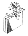
제 1 도는 본 발명에 따른 기록 헤드 코아 지지 요오크의 바람직한 실시예를 기록 헤드 코아가 조립된 상태로 도시한 사시도.1 is a perspective view showing a preferred embodiment of the recording head core support yoke according to the present invention with the recording head core assembled.
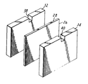
제 2 도는 제 1 도의 지지 요오크의 전개 사시도.2 is an exploded perspective view of the support yoke of FIG.
제 3 도는 제 1 도의 지지 요오크에 기록 헤드 코아를 조립하기 전에 지지 요오크를 도시한 전개 사시도.3 is an exploded perspective view showing the support yoke before assembling the recording head core to the support yoke of FIG.
제 4 도는 지지 요오크의 다른 실시예의 사시도.4 is a perspective view of another embodiment of a support yoke.
* 도면의 주요부분에 대한 부호의 설명* Explanation of symbols for main parts of the drawings
10 : 지지 요오크 12 : 영상기록 코아10: support yoke 12: video recording core
22, 24 : 코일 26 : 받침판22, 24: coil 26: support plate
28 : 받침면 32, 34 : 지지판28:
36 : 슬로트 38, 40 : 릴리프 포켓36:
본 발명은 자기 테이프 기록장치에 관한 것으로서, 더 구체적으로는 기록 테이프에 관하여 횡방향으로 이동하는 하나의 트랙 헤드를 사용해서 복수 트랙을 기록하도록 되어 있는 기록장치에 관한 것이다.TECHNICAL FIELD The present invention relates to a magnetic tape recording apparatus, and more particularly, to a recording apparatus configured to record a plurality of tracks by using one track head moving laterally with respect to the recording tape.
데이터 기록 카트리지 및 이를 사용하도록 되어 있는 기록장치가 미합중국 특허 제 3,692,255호(폰 베렌씨에게 특허됨)에 개시 및 청구되어 있다. 상기 특허에 개시된 카트리지에 있어서, 자기 기록 테이프는 디지탈 데이터 기록 및 재생에 있어서와 같이 테이프의 급속 가속 및 감속을 포함한 양방향 구동을 위하여 양리일 허브상에서 테이프와 마찰 접촉되는 가요성 무단 벨트와 함께 리일에서 리일로 이어지는 형태의 외함내에 장전되어 있다.A data recording cartridge and a recording device adapted to use it are disclosed and claimed in US Pat. No. 3,692,255 (patented by von Veren). In the cartridge disclosed in the patent, a magnetic recording tape is used in a rail together with a flexible endless belt in frictional contact with the tape on a bi-directional hub for bidirectional drive including rapid acceleration and deceleration of the tape as in digital data recording and playback. It is loaded in an enclosure that leads to a rail.
미합중국 특허 제 4,313,143호에는 상기 폰 베렌 특허에 사용되는 헤드 배치 기구가 개시되어 있는 바, 이는 데이터를 일련의 평행한 트랙들에 기록하도록 기록 헤드 코아를 자기 테이프의 횡방향으로 배치한다.U.S. Patent No. 4,313,143 discloses a head placement mechanism for use in the von Beren patent, which places the recording head core in the transverse direction of the magnetic tape to record data in a series of parallel tracks.
또한 미합중국 특허 제 4,300,179호에도 기록 헤드 코아를 지니며 자기 테이프를 코아에 관하여 그 이동방향의 횡방향으로 지지하는 기록 헤드 코아 요오크가 개시되어 있다. 이 요오크가 그 의도한 목적을 제대로 수행하였지만, 최근 기록 트랙 간격을 감소시킬 필요성에 의해 더 작은 기록 헤드 코아를 필요로 하게 되었고 이 코아는 종전의 요오크에 의하여 이루어지는 것보다 더 큰 측면 지지를 요하게 되었다.U.S. Patent No. 4,300,179 also discloses a recording head core yoke having a recording head core and supporting a magnetic tape in the transverse direction of its movement with respect to the core. Although this yoke served its intended purpose well, the recent need to reduce the recording track spacing has led to the need for smaller recording head cores, which have greater lateral support than that achieved by conventional yokes. It became necessary.
2개의 주요면들, 마주하는 단부들, 굴곡된 상부 모서리 및 단부들에 인접하게 2개의 권선 코일들을 지니는 납작한 장방형 몸체를 포함하는 영상 기록 코아는 현재 필요로 하는 평행기록 트랙 밀도를 제공하기에 적당하다로 판명된 크기를 갖는다. 그러나, 영상 기록 코아가 단단히 지지되어야만 적절한 트랙 밀도가 실현될 수 있다. 영상 기록 코아는 특히 깨지기 쉽기 때문에 또한 적절한 지지가 필요하다.An image recording core comprising a flat rectangular body with two major faces, opposite ends, a curved upper edge and two winding coils adjacent the ends is suitable for providing the parallel recording track density currently required. Have a size that turns out to be. However, an appropriate track density can be realized only when the video recording core is firmly supported. Image recording cores are particularly fragile and therefore require adequate support.
본 발명에 의하면 이러한 영상 기록 코아의 지지는 지지 요오크에 의하여 이루어지는 바, 이것은 기록 테이프를 테이프이동의 횡방향으로 지지하는 받침면, 영상 기록 코아를 수납하여 이를 그 길이를 따라 안정시키는 받침면에 수직하게 배치된 좁은 슬로트, 및 받침면 슬로트에 인접하여 끝을 이루어서 슬로트 양측에서 영상 기록 코아와 결합된 권선 코일을 수납하는 릴리프 포켓(relif pockets)을 형성하는 받침면에 접하는 지지면들을 포함한다.According to the present invention, the support of the image recording core is made by a support yoke, which is a support surface for supporting the recording tape in the transverse direction of tape movement, and a support surface for storing the image recording core and stabilizing it along its length. Support surfaces abutting the narrow slots arranged vertically and abutment surfaces forming end pockets adjacent the bearing slots and forming relief pockets receiving winding coils coupled with the image recording cores on both sides of the slot. Include.
상기 지지 요오크는 하나의 성형 또는 기계가공된 구조물로서 형성되거나, 혹은 본 발명의 다른 실시예에 따라 적층 구조물로 될 수도 있다. 본 발명은 또한 이같은 적층된 코아를 만드는 방법도 포함하는 바, 이 방법은 연속적인 상부 모서리를 지니는 납작한 장방형 받침판을 마련하고, 이 받침판과 전반적으로 크기가 동일한 2개의 납작한 장방형 지지판들을 마련하며, 지지판들 각각에 지지판의 모서리에서 개방된 릴리프 슬로트들을 형성하고, 지지판 릴리프 슬로트들이 정렬되고 받침판이 지지판들 사이에 있는 상태에서 지지판의 상부 모서리에 인접하도록 지지판들을 받침판에 부착시키며, 장착 슬로트가 받침판 상부 모서리에서 개방되고 지지판 릴리프 슬로트들의 중심에 오게 받침판과 지지판들을 통해 장착 슬로트를 형성하고, 릴리프 스르포트들을 포함하고 있는 받침판의 상부 모서리 및 지지판들의 모서리들을 영상 기록 코아의 연속적인 곡선과 매칭되는 연속적인 곡선으로 둥글게 만들며 영상 기록 코아를 장착 슬로트들에 장착하여 권선 코일들이 지지판 릴리프 슬로트들에 둘러 싸여지게 하는 것을 포함한다.The support yoke may be formed as one molded or machined structure, or may be a laminate structure in accordance with another embodiment of the present invention. The present invention also includes a method of making such stacked cores, which method provides a flat rectangular support plate having a continuous upper edge, and provides two flat rectangular support plates of generally the same size as the support plate, and a support plate. On each of them form relief slots open at the edges of the support plate, attaching the support plates to the support plate adjacent to the upper edge of the support plate with the support plate relief slots aligned and the support plate between the support plates, Form a mounting slot through the support plate and the support plates, which are open at the upper edge of the support plate and centered on the support plate relief slots, and the upper edge of the support plate containing the relief ports and the corners of the support plates are continuously Round with a matching curve It makes equipped with a video recording core mounted on the slotted involves winding coils are to be surrounded by the support plate the relief slotted.
이하 동일 부호가 동일 부분을 가리키는 첨부 도면을 참조하여 본 발명을 더 상세히 설명한다.DETAILED DESCRIPTION Hereinafter, the present invention will be described in more detail with reference to the accompanying drawings where like reference numerals designate like parts.
제 1 도는 영상 기록 헤드 코아(12)를 지지하는 전반적으로 부호(10)로 도시된 기록 헤드 코아 지지 요오크를 도시한다. 제 3 도에서 잘 알 수 있듯이, 코아는 영상 기록 기술에 이용되는 단일 또는 2중 갭(gap)형태로서 종래와 같은 것이며 이 기술 분야에 숙련된 자에게는 숙지된 것이다. 코아(12)는 2개의 주요면들, 마주하는 단부들 및 굴곡진 상부 모서리부(16)를 지니는 전반적으로 장방형인 납작한 몸체 부분(14)으로 이루어진다. 상부 모서리(16)는 기록용 및 기록된 자료의 재생용으로 각기 하나씩 2개의 자기 갭들(18, 20)을 포함하고 있다. 기록 코아(12)의 몸체(14)는 종래와 같이 망간 아연 페라이트 또는 니켈 아연 페라이트의 조성물 같은 자기 페라이트로 구성된다. 갭들(18, 20)에 나타나는 자속은 코아(12)의 주요면들을 넘어 연장되고 기록 장치(도시되지 않음)에 적절히 접속된 권선 코일들(22, 24)에 의하여 제어된다.FIG. 1 shows the recording head core support yoke shown generally by the
다시 제 1 도에서, 기록 헤드 코아 지지 요오크(10)의 바람직한 실시예는 상부 받침면(28)을 지니는 중앙 받침판(26)을 포함하고 있는 적층 구조물로 된다. 지지 요오크(10)는 미합중국 특허 제 4,313,143호에 기술된 바와같은 기록장치에 사용하려는 것으로서, 이 장치는 양방향 화살표(30)로 표시되는 방향으로 이동하는 자기 테이프(도시되지 않음)에 관하여 코아(12)를 배치한다. 그러나, 코아(12)와 요오크(10)는 디스크 같은 다른 자기 기록 매체와도 사용될 수 있다.Again in FIG. 1, a preferred embodiment of the recording head
코아(12)는 테이프 이동방향에 관하여 횡으로 이동되어 기록 테이프상에 일련의 간격진 평행한 정보 트랙들을 기록한다. 코아(12)가 기록 테이프에 관하여 횡으로 이동하므로, 받침면(28)은 기록 테이프를 그 전체폭에 걸쳐서 지지하기에 충분한 길이로 되어야 한다. 이와같이 하기 위해서, 요오크(10)는 코아(12)로부터 각 방향으로 최소한 기록 테이프 자체의 폭과 같은 거리까지 연장되어야 한다. 예컨대, 테이프 폭이 8mm이면, 코아(12)에서 요오크(10)의 모서리까지의 거리는 최소한 8mm 이어야 한다. 다시 말해서 받침면(28)의 전체 길이는 최소한 기록 테이프의 폭의 2배로 되어야 한다. 코아(12)가 기록 테이프를 완전히 벗어나게 배치되는 것도 예상될 수 있고, 이 경우에 요오크(10)의 양 측부들중의 하나는 기록 테이프의 폭보다 약간 길어야 한다.The
기록 테이프를 부가적으로 지지하기 위하여, 지지 요오크(10)는 받침판(26)의 각 주요면에 접착되는 2개의 지지판들(32, 34)을 구비하고 있다. 이 지지판들(32, 34)은 기록 테이프를 더욱 완전히 지지하여 조립체의 견고성을 증가시킨다.In order to additionally support the recording tape, the
받침판(26)과 지지판들(32, 34)은 바륨 티타네이트 또는 칼슘 티타네이트 같은 세라믹 재료로 만들어지는 것이 바람직하고 에폭시재료 또는 유리 접착제로 서로 접착된다.The
기록 코아(12)를 수용하기 위하여, 받침판(26)과 지지판들(32, 34)은 기록 코아(12)를 밀접하게 수용하며 코아(12)를 그 하부 모서리를 따라 그리고 권선 코일들(22)의 사이에서 전체 길이를 따라 지지하는 좁은 슬로트(36)가 구비되어 있다. 좁은 슬로트(36)는 받침판(26)의 받침면(28)까지 완전히 연장되어서 코아(12)의 전체 길이에 걸쳐서 측면을 지지한다. 인접되어 있는 받침판(26)과 지지판들(32, 34)은 각기 권선 코일들(22)를 수요하고 또한 공간을 형성하는 릴리프 포켓들(38, 40)이 형성되어 있다.In order to receive the
마지막으로, 받침면(28) 및 인접해 있는 지지판들(32, 34)의 상면들은 기록 테이프를 마모시키거나 또는 손상시킬 수도 있는 날카로운 모서리를 제거하기 위하여 기록 코아(12)의 상부 모서리(16)와 동일한 형상이 되도록 둥글게 만들어진다. 코아(12)는 기록 테이프와 적절한 접촉을 확보하도록 받침면(28)의 위로 약 0.3mm 돌출하는 것이 바람직하고, 지지 요오크(10)를 만드는데 다양한 재료가 사용될 수 있지만 마모를 막도록 세라믹이 좋으며 이 세라믹은 코아(12)가 항상 돌출하게 하도록 요오크(10)가 코아(12)보다 더 약간 빨리 마모되게 하는 마모특성을 갖는 것이 바람직하다.Finally, the top surface of the
제 2 도와 제 3 도는 제 1 도의 적층된 지지 요오크(10)를 제조하는 바람직한 방법을 도해한 것이다. 제 2 도에 도시된 바와같이, 본 발명의 방법은 받침면(28)을 형성하는 연속적인 상부 모서리를 지니는 납작한 장방형 받침판(26)를 마련하고, 받침판(26)과 전반적으로 크기가 동일한 2개의 납작한 장방형 지지판들(32, 34)을 마련하며, 지지판들(32, 34)의 각각에 받침판(26)과 인접한 지지판들(32, 34)의 모서리 부분에서 개방되어 있는 릴리프 슬로트들 또는 포켓들(38, 40)을 형성하고, 지지판 릴리프 슬로트들(38, 40)이 정렬되고 받침판(26)의 받침면(28)에 인접되어 받침판(26)이 지지판들(32, 34)의 사이에 놓이도록 제 3 도에 도시된 바와같이 지지판들(32, 34)을 받침판(26)에 부착시키며, 장착 슬로트들(36)이 받침면(28)에서 개방되고 지지판 릴리프 슬로트들(38, 40)내의 중심에 오며 제 1 도에 도시된 바와같이 받침판(26)의 상부 모서리 및 릴리프 슬로트들(38, 40)을 포함하고 있는 지지판들(32, 34)의 모서리들이 기록 코아(12)의 곡선부와 매칭되는 연속적인 곡선으로 둥글게 만들어지게 장착 슬로트(36)를 받침판(26)과 지지판들(32, 34)을 통하여 형성하는 단계들로 이루어진다. 이어서 기록 코아(12)는 제 1 도에 도시된 완성된 조립체를 형성하도록 슬로트(36)에 에폭시로 장착되는 것이 좋다.2 and 3 illustrate a preferred method of making the
릴리프 슬로트들(38, 40)은 단순히 권선 코일들(22)의 공간을 형성하는 것이므로 크기가 중요하지는 않다. 따라서, 이러한 슬로트들(38, 40)은 기계가공, 에칭 또는 미세 분말의 성형가능한 세라믹이 이용된다면 성형같은 여러가지 방법으로 만들어진다. 그러나 좁은 지지 슬로트(36)는 코아(12)의 길이를 지지해야 되고, 따라서 코아(12)의 두께 치수에 대체로 0.01mm의 대단히 엄밀한 공차로 정확히 절단되어야 한다. 받침판(26)과 지지판들(32, 34)에 좁은 슬로트(36)를 형성하는 바람직한 방법은 정밀 기계가공이다.The size of the
그러나, 슬로트(36)의 깊이는 그 폭처럼 정밀하지는 않으며, 코아(12)가 요오크(10)에 부착될때 코아(12)의 배치를 용이하게 하기 위하여 와이어 또는 유사한 공구가 기록 코아(12)의 밑의 슬로트(36)로 삽입될 수 있도록 코아(12)를 수용하는데 필요한 깊이 보다 더 깊게 좁은 슬로트(36)를 절단하는 것이 바람직하다.However, the depth of the
제 4 도는 알루미늄 같은 재료의 하나의 블록으로 만들어지는 지지 요오크(50)의 다른 실시예를 도시한다. 알루미늄이 이용된다면, 적절한 마모 특성을 나타내도록 조절된 산화에 의하여 경질 피복된다. 제 4 도의 요오크(50)가 비록이어진 블록일지라도, 이것은 두 점선들(54, 56)사이에 놓이는 중앙 받침면(52)을 포함하는 것으로 생각될 수도 있다. 좁은 슬로트(58)는 이 받침면(52)의 길이의 대략 중심에서 절단되고 기록 코아(12)의 전체 길이를 지지하는데 이용된다. 받침면(52)에 인접하게 2개의 지지면들(60, 62)이 기록 코아(12)와 결합된 권선 코일들(22)을 수납하는 릴리프 포켓들(64, 66)을 형성하도록 좁은 슬로트(58)에 인접해서 끝을 이룬다. 좁은 슬로트(58)와 릴리프 포켓들(64, 66)은 전술한 이유로 슬로트(58)의 폭에 특히 주의를 하는 한에 있어서는 어떤 순서로 절단되어도 좋다.4 illustrates another embodiment of
제 4 도의 지지 요오크(50)가 만족할만하게 동작하는 것이 밝혀졌으나, 지지 요오크(10)를 세라믹 재료로 만드는 것이 바람직하므로 제 1-3 도의 적층 구조가 더 바람직하다. 세라믹 재료는 금속처럼 쉽게 기계가공되지 않으므로 지지 요오크(10)를 필요한 치수 정도를 유지하면서 세라믹 재료의 견고한 블록으로 만들어내는 것은 대단히 어렵다.Although it has been found that the
비록 본 발명을 단지 한정된 수의 실시예들에 관하여 설명하였지만, 본 기술 분야에 숙련된 자에게 수많은 변형이 자명함을 알아야 한다. 예컨대, 요오크(10)와 코아(12)의 상면들은 평평하게 놔 둘 수 있고 릴리프 슬로트 또는 포켓들(38, 40 또는 64, 66)은 권선 코일(22)을 수용하는데 필요한 깊이 이상으로 연장될 수 있다. 또한, 지지 요오크(10 또는 50)에 하나 이상의 기록 코아(12)를 구비하는 것이 바람직할 수도 있다. 다수의 별개 트랙들이 동시에 기록될 수 있으므로 복수 코아들(12)을 지니는 구성이 유용할 수도 있다.Although the present invention has been described with reference to only a limited number of embodiments, it should be understood that many variations will be apparent to those skilled in the art. For example, the top surfaces of the
본 발명은 첨부되는 특허 청구의 범위의 원리와 범위에 속하는 이러한 모든 변형들을 포함하려는 것이다.It is intended that the present invention cover all such modifications as fall within the spirit and scope of the appended claims.
Claims (9)
Applications Claiming Priority (3)
| Application Number | Priority Date | Filing Date | Title |
|---|---|---|---|
| US749.938 | 1985-06-27 | ||
| US749,938 | 1985-06-27 | ||
| US06/749,938 US4686596A (en) | 1985-06-27 | 1985-06-27 | Recording head core yoke and method of manufacture |
Publications (2)
| Publication Number | Publication Date |
|---|---|
| KR870000680A KR870000680A (en) | 1987-02-19 |
| KR950000558B1 true KR950000558B1 (en) | 1995-01-24 |
Family
ID=25015852
Family Applications (1)
| Application Number | Title | Priority Date | Filing Date |
|---|---|---|---|
| KR1019860005113A KR950000558B1 (en) | 1985-06-27 | 1986-06-26 | Recording head core yoke and manufacturing method thereof |
Country Status (6)
| Country | Link |
|---|---|
| US (1) | US4686596A (en) |
| JP (1) | JPS628308A (en) |
| KR (1) | KR950000558B1 (en) |
| AT (1) | AT393567B (en) |
| DE (1) | DE3619010A1 (en) |
| NL (1) | NL8601632A (en) |
Families Citing this family (10)
| Publication number | Priority date | Publication date | Assignee | Title |
|---|---|---|---|---|
| US5055959A (en) * | 1990-01-09 | 1991-10-08 | Digital Equipment Corporation | Tape head with low spacing loss produced by narrow and wide wear regions |
| US5124866A (en) * | 1990-02-01 | 1992-06-23 | Minnesota Mining And Manufacturing Company | Recording head core yoke with full length core support |
| US5179486A (en) * | 1990-09-06 | 1993-01-12 | Minnesota Mining And Manufacturing Company | Head positioning and tape support apparatus for data recorder |
| US5426551A (en) * | 1993-07-19 | 1995-06-20 | Quantum Corp. | Magnetic contact head having a composite wear surface |
| JPH09503606A (en) * | 1993-07-19 | 1997-04-08 | クウォンタム・コーポレイション | Magnetic head with self-regulating wear area |
| US6937435B2 (en) * | 2003-05-16 | 2005-08-30 | Quantum Corporation | Tape head with thin support surface and method of manufacture |
| US7154691B2 (en) * | 2003-12-18 | 2006-12-26 | Quantum Corporation | Multi-format thinfilm head and associated methods |
| US7256963B2 (en) * | 2004-09-16 | 2007-08-14 | Quantum Corporation | Magnetic head with adaptive data island and mini-outrigger and methods of manufacture |
| US7271983B2 (en) * | 2004-09-16 | 2007-09-18 | Quantum Corporation | Magnetic head with mini-outriggers and method of manufacture |
| US20070183091A1 (en) * | 2006-02-03 | 2007-08-09 | Saliba George A | Read/write head having varying wear regions and methods of manufacture |
Family Cites Families (5)
| Publication number | Priority date | Publication date | Assignee | Title |
|---|---|---|---|---|
| US3846840A (en) * | 1973-08-10 | 1974-11-05 | Ibm | Read/write and longitudinal edge erase head assembly having multiple similarly shaped layers |
| US4313143A (en) * | 1979-09-04 | 1982-01-26 | Minnesota Mining And Manufacturing Co. | Head positioning mechanism for data cartridge recorder |
| US4300179A (en) * | 1979-09-04 | 1981-11-10 | Minnesota Mining And Manufacturing Co. | Composite magnetic head with multitrack support structure |
| DE3103767C2 (en) * | 1980-02-04 | 1986-12-04 | Sanyo Electric Co., Ltd., Moriguchi, Osaka | Magnetic head |
| US4803582A (en) * | 1983-06-23 | 1989-02-07 | Victor Company Of Japan Ltd. | Perpendicular magnetization type magnetic head having a magnetic pole part which forms a closed magnetic path |
-
1985
- 1985-06-27 US US06/749,938 patent/US4686596A/en not_active Expired - Fee Related
-
1986
- 1986-05-26 JP JP61120945A patent/JPS628308A/en active Granted
- 1986-06-06 DE DE19863619010 patent/DE3619010A1/en not_active Withdrawn
- 1986-06-12 AT AT1600/86A patent/AT393567B/en not_active IP Right Cessation
- 1986-06-24 NL NL8601632A patent/NL8601632A/en not_active Application Discontinuation
- 1986-06-26 KR KR1019860005113A patent/KR950000558B1/en not_active IP Right Cessation
Also Published As
| Publication number | Publication date |
|---|---|
| KR870000680A (en) | 1987-02-19 |
| ATA160086A (en) | 1991-04-15 |
| NL8601632A (en) | 1987-01-16 |
| JPH0542047B2 (en) | 1993-06-25 |
| DE3619010A1 (en) | 1987-01-02 |
| US4686596A (en) | 1987-08-11 |
| JPS628308A (en) | 1987-01-16 |
| AT393567B (en) | 1991-11-11 |
Similar Documents
| Publication | Publication Date | Title |
|---|---|---|
| KR950000558B1 (en) | Recording head core yoke and manufacturing method thereof | |
| US5124866A (en) | Recording head core yoke with full length core support | |
| US5105529A (en) | Process for airborne monolithic ferrite recording head with glass-protected self-aligned, machined track | |
| JPH07334953A (en) | Magnetic disk device assembling method | |
| US3978523A (en) | Multi-channel dual-gap magnetic head | |
| US3969770A (en) | Two-track bidirectional cassette head for data handling apparatus | |
| JPH02244420A (en) | Floating type magnetic head | |
| US5179486A (en) | Head positioning and tape support apparatus for data recorder | |
| EP0097975A3 (en) | Magnetic head for a perpendicular read/write arrangement | |
| US4435736A (en) | Isolated multiple core magnetic transducer assembly | |
| EP0196605A2 (en) | Magnetic head assembly | |
| US4672495A (en) | Thin-film magnetic head | |
| US3542971A (en) | Magnetic transducer having positioning surfaces | |
| US3763329A (en) | Four-track magnetic head for tape recording devices | |
| US6175473B1 (en) | Magnetic head in which a core assembly is mounted on a rail formed on a slider | |
| US3564520A (en) | Magnetic head assembly | |
| US3394362A (en) | Magnetic head assembly with receivers for pole pieces | |
| KR860001411A (en) | Magnetic head for vertical magnetic recording and its manufacturing method | |
| JPS6047271A (en) | Floating head | |
| KR890007479Y1 (en) | United magnetic head | |
| JPH03119507A (en) | Magnetic head | |
| JP2587479Y2 (en) | Multi-loading recording media automatic performance device | |
| JPH09219006A (en) | Magnetic head, two channels magnetic head, and magnetic storage device using these heads | |
| JPS60132663U (en) | magnetic recording and reproducing device | |
| JPS60219616A (en) | Magnetic head holder |
Legal Events
| Date | Code | Title | Description |
|---|---|---|---|
| A201 | Request for examination | ||
| G160 | Decision to publish patent application | ||
| E701 | Decision to grant or registration of patent right | ||
| GRNT | Written decision to grant | ||
| FPAY | Annual fee payment |
Payment date: 19971230 Year of fee payment: 4 |
|
| LAPS | Lapse due to unpaid annual fee |