KR940004944B1 - Manufacturing apparatus for tab terminal - Google Patents

Manufacturing apparatus for tab terminal Download PDF

Info

Publication number
KR940004944B1
KR940004944B1 KR1019880002939A KR880002939A KR940004944B1 KR 940004944 B1 KR940004944 B1 KR 940004944B1 KR 1019880002939 A KR1019880002939 A KR 1019880002939A KR 880002939 A KR880002939 A KR 880002939A KR 940004944 B1 KR940004944 B1 KR 940004944B1
Authority
KR
South Korea
Prior art keywords
tab terminal
tab
press
wire
aluminum wire
Prior art date
Application number
KR1019880002939A
Other languages
Korean (ko)
Other versions
KR880011839A (en
Inventor
노부히로 나라자와
쥰 오노시로
유기오 이도오
히데유끼 다끼자와
고오이찌 고이께
Original Assignee
히다찌 덴시 엔지니어링 가부시기가이샤
나까다 구스오
Priority date (The priority date is an assumption and is not a legal conclusion. Google has not performed a legal analysis and makes no representation as to the accuracy of the date listed.)
Filing date
Publication date
Application filed by 히다찌 덴시 엔지니어링 가부시기가이샤, 나까다 구스오 filed Critical 히다찌 덴시 엔지니어링 가부시기가이샤
Publication of KR880011839A publication Critical patent/KR880011839A/en
Application granted granted Critical
Publication of KR940004944B1 publication Critical patent/KR940004944B1/en

Links

Images

Classifications

    • HELECTRICITY
    • H01ELECTRIC ELEMENTS
    • H01GCAPACITORS; CAPACITORS, RECTIFIERS, DETECTORS, SWITCHING DEVICES OR LIGHT-SENSITIVE DEVICES, OF THE ELECTROLYTIC TYPE
    • H01G4/00Fixed capacitors; Processes of their manufacture
    • H01G4/002Details
    • H01G4/228Terminals

Landscapes

  • Engineering & Computer Science (AREA)
  • Power Engineering (AREA)
  • Manufacturing & Machinery (AREA)
  • Microelectronics & Electronic Packaging (AREA)
  • Fixed Capacitors And Capacitor Manufacturing Machines (AREA)
  • Manufacturing Of Electrical Connectors (AREA)

Abstract

내용 없음.No content.

Description

탭단자의 제조장치Tap Terminal Manufacturing Equipment

제1도 탭단자의 제조 장치의 전체 구성을 나타낸 사시도.1 is a perspective view showing the overall configuration of a manufacturing apparatus of a tab terminal.

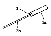
제2a도는 탭단자 구성체의 외관도, 제2b도는 탭단자의 외관도.FIG. 2A is an external view of a tab terminal structure, and FIG. 2B is an external view of a tab terminal structure.

제3도는 용접부의 구성 및 작용을 나타낸 설명도.3 is an explanatory diagram showing the configuration and operation of the welded portion.

제4도는 용접 공정의 작용 설명도.4 is an explanatory diagram of the operation of the welding process.

제5도는 CP선 커터의 구성 설명도.5 is a diagram illustrating the configuration of a CP line cutter.

제6도는 이재용 척부재의 주요부분 정면도.6 is a front view of the main part of the chuck member for the transfer material.

제7도는 제6도의 평면도.7 is a plan view of FIG.

제8도는 인덱스 테이블위에 설치한 반송용 척부재의 구성 설명도.8 is an explanatory diagram of a configuration of a conveying chuck member provided on an index table.

제9도는 제8도의 부분 단면 측면도.9 is a partial cross-sectional side view of FIG.

제10도는 반송용 척부재의 정면도.10 is a front view of the conveying chuck member.

제11도는 프레스부의 구성 설명도.11 is an explanatory view of the configuration of the press section.

제12도는 배출부의 구성 설명도.12 is an explanatory view of the configuration of the discharge unit.

제13도는 가동부의 구동기구를 나타낸 구성 설명도.Fig. 13 is an explanatory diagram of the structure showing the drive mechanism of the movable section.

제14도는 구동부의 구성 설명도.14 is an explanatory view of the configuration of a drive unit.

* 도면의 주요부분에 대한 부호의 설명* Explanation of symbols for main parts of the drawings

1 : 알루미늄선 2 : CP선1: aluminum wire 2: CP wire

3 : 탭(tap) 단자 구성체 3a : 탭형성부3: Tap terminal structure 3a: Tap forming unit

3b :리이드부 23 : 이재용 척(chuck) 부재3b: lead portion 23: chuck member for transfer

35 : 인덱스 테이블(index table) 48 : 하부펀치35 index table 48 lower punch

55 : 정렬용기 56a, 56b : 전자석55: alignment container 56a, 56b: electromagnet

58 : 반전(反轉) 바아 61 : 고정부58: inversion bar 61: fixed part

W : 용접부 P : 프레스부W: Welding part P: Pressing part

T : 탭단자 R : 배출부T: Tap terminal R: Outlet

본 발명은 콘덴서의 전극을 구성하는 탭단자의 제조 장치에 관한 것이다.The present invention relates to an apparatus for manufacturing a tab terminal constituting an electrode of a capacitor.

콘덴서의 전극을 구성하는 탭단자는 탭형성부와 리이드부를 지니고 있으며, 탭형성부에 알루미늄박을 감아붙임에 따라 형성되므로 동 탭단자는 알루미늄선(線)과 CP선을 사용하며, 알루미늄선을 일정한 길이로 절단하여 CP선의 선단에 맞댄 상태에서 용접하고, CP선을 일정한 길이로 절단함에 따라서, 우선 탭형성부를 구성하는 짧은 알루미늄선 부분과 그보다 긴 CP선으로 리이드부로 된 탭단자 구성체를 형성한 다음, 탭단자 구성체에 있어서의 알루미늄선 부분을 프레스 수단으로 편평하게 되도록 가압 변형시킴과 동시에, 그것이 일정한 형상이 되도록 정형하여 탭형성부를 성형함에 따라 제조된다.The tab terminal constituting the electrode of the capacitor has a tab forming portion and a lead portion, and is formed by winding an aluminum foil on the tab forming portion. Therefore, the tab terminal uses aluminum wire and CP wire, By cutting to a certain length and welding it to the end of the CP line, and cutting the CP line to a certain length, first, a short aluminum wire portion constituting the tab forming portion and a tab terminal structure composed of a lead portion are formed from a longer CP line. Next, the aluminum wire portion in the tab terminal structure is pressed and deformed so as to be flattened by the press means, and shaped so as to have a constant shape, thereby forming the tab forming portion.

그리고, 전술한 바와같이 탭단자를 제조하기 위하여 알루미늄선과 CP선을 용접하는 용접 장치와, 탭단자 구성체를 프레스하여 정형하는 프레스 장치를 필요로 한다. 그런데, 종래 기술에서는 용접 장치와 프레스 장치를 각기 따로따로 설치하도록 한 것은 알려져 있다. 따라서, 이 용접 장치와 프레스 장치 사이에는 공작물의 이행을 하게 하기 위한 기구를 설치할 필요가 있으나, 그와 같은 공작물의 이행수단으로서 직전 피이터를 사용하고, 이 직전 피이터로 탭형성부와 리이드부 사이의 용접 부분을 끼워둔 상태에서 용접 장치로부터 프레스장치에 이송하도록 구성하여 왔다.As described above, in order to manufacture the tab terminal, a welding device for welding the aluminum wire and the CP wire and a press device for pressing and shaping the tab terminal structure are required. By the way, in the prior art, it is known that the welding apparatus and the press apparatus are separately provided. Therefore, it is necessary to provide a mechanism for shifting the workpiece between the welding device and the press device. However, a tap forming portion and a lead portion are used as the immediately preceding feeder as the means for transferring the workpiece. It has been comprised so that it may transfer from a welding apparatus to a press apparatus in the state which sandwiched the welding part in between.

그러나, 이와 같이 구성하면 장치 전체의 구성이 대형화함과 동시에 직전 피이터에 의한 탭단자 구성체의 이송을 고화 할 수 없게 될 뿐만 아니라, CP선과 알루미늄선 사이의 용접 부분의 형상이 일정하지 않기 때문에 용접 부분을 직진 피이터로 끼워두어 이송하도록 하였을 경우에는 그 반송이 현저히 불안정하게 되어 공작물의 장애가 발생한다던가 하는 불합리가 있어, 이 때문에 제조 효율이 나빠서 대량 생산에 부합할 수 없다고 하는 결점이 있었다.However, this configuration not only increases the overall configuration of the apparatus but also prevents the transfer of the tab terminal components by the previous feeder, and also prevents the shape of the weld portion between the CP wire and the aluminum wire from being constant. In the case where the portion is sandwiched by a straight line feeder, the conveyance becomes remarkably unstable, and there is an unreasonability that a failure of the workpiece occurs. Therefore, there is a drawback that the manufacturing efficiency is poor and the mass production cannot be met.

본 발명은 전술한 점에 비추어서 이루어 놓은 것으로, 그 목적으로 하는 바는 소형으로 콤팩트한 구성에 따라 극히 높은 효율로 고속으로 탭단자를 제조할 수 있는 탭단자의 제조장치를 제공함에 있다.SUMMARY OF THE INVENTION The present invention has been made in view of the foregoing, and an object thereof is to provide a tap terminal manufacturing apparatus capable of manufacturing a tab terminal at a high speed with extremely high efficiency according to a compact and compact configuration.

전술한 목적을 달성하기 위하여 본 발명은 알루미늄선을 일정한 길이로 절단하여 CP선의 선단에 맞닿게 하여 용접을 한 다음에, CP선을 일정한 길이로 절단함에 따라 탭단자 구성체를 형성하는 용접부와, 용접부에서 탭단자 구성체에 있어서의 CP선의 절단전의 상태로 고정하고, 절단후에 180°회전운동시킴에 따라 전술한 탭단자 구성체를 반전시키는 이재용 척부재와, 인덱스 테이블위에 설치되어 이재용 척부재로부터 탭단자 구성체를 받아서 인덱스 테이블을 회전운동시킴에 따라 프레스부에 반입하고, 탭단자 구성체의 알루미늄 선부를 프레스하여 편평하게 되도록 가압 변형시킴과 동시에, 일정한 형상으로 정형함에 따라 탭형성부를 성형하는 프레스부와, 이 프레스부에서 형성된 탭단자를 수납하는 수납부로 구성한 것을 특징으로 한다.In order to achieve the above object, the present invention is welded by cutting the aluminum wire to a certain length to abut the tip of the CP line to weld, then forming a tab terminal structure by cutting the CP line to a constant length, and a welded portion The chuck member for displacing the above described tab terminal structure by fixing it in the state before the cutting of the CP line in the tab terminal structure, and rotating 180 ° after the cutting, and the tab terminal structure installed on the index table from the chuck member for the displacing material. A press unit for carrying out the index table into the press unit by rotating the index table, pressing and deforming the aluminum wire of the tab terminal member to be flat, and shaping the tab forming unit according to shaping to a certain shape; Characterized in that it comprises a receiving portion for receiving the tab terminal formed in the press portion.

다음에, 본 발명의 실시예를 도면에 따라 상세히 설명한다.Next, embodiments of the present invention will be described in detail with reference to the drawings.

우선, 제1도는 탭단자의 제조 장치의 전체를 나타낸 것으로, 도면중에서 (1)은 탭부를 형성하는 알루미늄선, (2)는 리이드를 형성하는 CP선을 각기 나타내고 있으며, 이것들 알루미늄선 (1) 및 CP선(2)은 공급부(S)로부터 용접부(W)에 공급되도록 되어 있다.First, FIG. 1 shows the entire manufacturing apparatus of a tab terminal. In the drawing, reference numeral 1 denotes an aluminum wire forming a tab portion, and 2 denotes a CP wire forming a lead. These aluminum wires 1 And the CP line 2 are supplied to the welding part W from the supply part S. FIG.

용접부에 공급된 알루미늄선(1) 및 CP선(2)은 용접부(W)에서 먼저 알루미늄선(1)을 일정한 길이로 절단하여 그것을 CP선(2)의 선단에 맞닿게 하여 용접함에 따라서 그것들 사이의 연결 고정 부착하여 제2a도에 나타낸 바와 같이 알루미늄선(1)으로 된 탭형성부(3a)와 CP선(2)으로 된 리이드부(3b)를 지닌 탭단자 구성체(3)가 형성된다. 이 탭단자 구성체(3)는 프레스부(P)에 반송되며, 이 프레스부(P)에서 탭형성부(3a)를 프레스하여 편평하게 되도록 가압 변형함과 함께, 이 편평 부분이 일정한 형상으로 되도록 정형하게 된다. 이에 따라서 제2a도에 나타낸 바와 같이, 탭단자(T)(콘덴서의 전극으로서 형성하는 경우에 있어서는 리이드부의 길이가 다른 한 쌍의 탭단자(T1), (T2)가 사용된다)가 형성되어서 배출부(R)에 배출되도록 되어 있다.The aluminum wire 1 and the CP wire 2 supplied to the weld portion are first cut into the aluminum wire 1 to a predetermined length in the weld portion W, and the aluminum wire 1 and CP wire 2 are brought into contact with the tip of the CP wire 2 and welded therebetween. As shown in FIG. 2A, a tab terminal structure 3 having a tab forming portion 3a made of aluminum wire 1 and a lead portion 3b made of CP line 2 is formed. This tab terminal structure 3 is conveyed to the press part P, press-presses the tab forming part 3a in this press part P, and deforms it so that it may become flat, and this flat part may become a fixed shape. It is formulated. As a result, as shown in FIG. 2A, the tab terminal T (a pair of tab terminals T1 and T2 having different lengths of the lead portion in the case of forming as an electrode of the capacitor) is formed and discharged. It is supposed to be discharged to the portion R.

여기에서, 공급부(S)로서는 각기 길게 형성한 알루미늄선(1) 및 CP선(2)을 돌려감는 물레(4), (5)가 설치되어 있음과 동시에, 각 물레(4), (5)로부터 송출되는 알루미늄선(1), CP선(2)을 직선상태로 보내도록 교정하기 위한 가이드 로울러(6), (7)가 설치되어 있다.Here, as the supply part S, the spinning wheels 4 and 5 which turn around the aluminum wire 1 and CP line 2 which were each formed long are provided, and each spinning wheel 4 and 5 are provided. Guide rollers 6 and 7 for calibrating the aluminum wire 1 and the CP wire 2 to be sent out from each other in a linear state are provided.

다음에, 용접부(W)는 제3도에 나타낸 바와같이 알루미늄선(1) 및 CP선(2)을 클램프(clamp)하여 끌어내기 위한 후송 방지 장치 부착의 보올클램프(8), (9)가 설치되어 있으며, 각 보올클램프(8), (9)는 슬라이더(10), (11)에 따라 가이드 로드(12), (13)에 잇따라서 왕복 이동할 수 있도록 되어 있다. 그리고, 각 슬라이더(10), (11)에는 제1도로부터 명백한 바와같이, 캠기구(도면에 없음)에 의하여 구동되는 레버(14), (15)에 따라 구동되며, 각 슬라이더(10), (11)가 전진할 때에는 각 보올클램프(8), (9)는 각기 알루미늄선(1) 및 CP선(2)을 클램프한 상태에서 끌어내고, 또 슬라이더(10), (11)가 후퇴할 때에는 보올클램프(8), (9)에 의한 클램프를 해제하도록 되어 있다.Next, as shown in FIG. 3, the welding portion W is provided with the ball clamps 8 and 9 with the anti-feedback device for clamping and pulling out the aluminum wire 1 and the CP wire 2. Each of the bowl clamps 8 and 9 can be reciprocated in succession with the guide rods 12 and 13 along the sliders 10 and 11. Each slider 10, 11 is driven by levers 14, 15 driven by a cam mechanism (not shown), as is apparent from FIG. 1, and each slider 10, When (11) moves forward, each of the bowl clamps (8) and (9) is pulled out while clamping the aluminum wire (1) and the CP wire (2), respectively, and the sliders (10) and (11) retreat. At this time, the clamps by the bowl clamps 8 and 9 are released.

전술한 바와 같이 끌어낸 알루미늄선(1)은 알루미늄선 다이스(16)에 삽통되도록 되어 있다. 알루미늄선 다이스(16)의 선단의 측부에는 알루미늄선 커터(17)가 알루미늄선 다이스(16)의 선단면에 잇따라서 왕복 이동할 수 있도록 장착되어 있으며, 이 다이스(16)로부터 알루미늄선(1)을 일정량 돌출시킨 상태에서 커터(17)를 전진시킴에 따라 상기 알루미늄선(1)의 절단을 할 수 있도록 되어 있다. 그리고 이 알루미늄선(1)의 절단시에 알루미늄선(1)을 고정하여 절단된 알루미늄선(1)을 CP선(2)의 선단에 대면한 용접위치에 공급하기 위한 용접을 척부재(8)가 다이스(16)의 연장선상에서 왕복 이동할 수 있도록 설치되어 있다.As described above, the drawn aluminum wire 1 is inserted into the aluminum wire die 16. The aluminum wire cutter 17 is attached to the side of the front end of the aluminum wire die 16 so that the aluminum wire cutter 17 can reciprocate in succession with the front end surface of the aluminum wire die 16, and the aluminum wire 1 is removed from the die 16. The aluminum wire 1 can be cut by advancing the cutter 17 in a state of protruding a certain amount. Then, the chuck member 8 performs welding for supplying the cut aluminum wire 1 by cutting the aluminum wire 1 to the welding position facing the tip of the CP wire 2 when the aluminum wire 1 is cut. Is installed so as to reciprocate on an extension line of the die 16.

한편, 보올클램프(9)로부터 끌어낸 CP선(2)은 CP선 노즐(19)을 통과하도록 되어있으며, 또 CP선 노즐(19)에 있어서의 받침대부(19a) 위에는 CP선(2)을 받침대부(19a)에 세개 누리기 위한 스프링판(19b)가 설치되어 있고, CP선(2)은 받침대부(19a)와 스프링판(19b) 사이에 끼워있게 된다. 그리고, 스프링판(19b)에는 요동레버(20)에 부착한 압동구(壓動驅)(20a)가 붙었다 떨어졌다 할 수 있도록 설치되어 있으며, 이 압동구(20a)를 스프링판(19b)에 눌러닿게 함에 따라 용접시에 CP선(2)이 움직이지 않도록 고정할 수 있도록 되어 있다.On the other hand, the CP line 2 drawn out from the bowl clamp 9 passes through the CP line nozzle 19, and the CP line 2 is placed on the pedestal portion 19a of the CP line nozzle 19. Three spring plates 19b are provided on the pedestal portion 19a, and the CP line 2 is sandwiched between the pedestal portion 19a and the spring plate 19b. The spring plate 19b is provided so that the pushing hole 20a attached to the swing lever 20 can be attached to and detached from the spring plate 19b, and the pushing plate 20a is attached to the spring plate 19b. As it presses against, it can fix so that CP line 2 may not move at the time of welding.

그리고, 전술한 바와 같이 알루미늄선(1)이 CP선(2)의 선단과 대면하는 용접위치에 이동하였을 때에, 제4도에 나타낸 바와 같이, 그 용접을 척부재(18)와, CP선 노즐(19)사이에 전류를 흐르게 하여, 이와 함께 압동레버(21)에 의하여 용접용 척부재(18)를 가이드(18a)에 잇따라서 CP선(2)의 축선방향으로 향하여 눌러 움직임에 따라 알루미늄선(1)을 CP선(2)에 맞닿게 하여 용접을 할 수 있도록 되어 있다. 이와같이 용접용 척부재(18)에 고정시킨 알루미늄선(1)을 용접시에 CP선(2)의 축선방향으로 이동시키도록 함에 따라서 양자 사이에 중심 차이가 발생하는 것을 방지할 수 있도록 되어 있다. 이 용접을 한 다음에 CP선(2)을 일정한 길이가 되도록 절단하기 위하여 CP선 커터(22)를 설치하고 있다.As described above, when the aluminum wire 1 moves to the welding position facing the tip end of the CP wire 2, as shown in FIG. 4, the welding is performed by the chuck member 18 and the CP wire nozzle. The electric current flows between the 19 and the aluminum chuck according to the movement by pressing the welding chuck member 18 along the guide 18a in the axial direction of the CP wire 2 by the pressure lever 21. The welding is carried out by bringing (1) into contact with the CP line 2. In this way, the aluminum wire 1 fixed to the welding chuck member 18 is moved in the axial direction of the CP line 2 at the time of welding, thereby preventing the center difference from occurring. After this welding, the CP line cutter 22 is provided in order to cut the CP line 2 to a certain length.

상기 CP선 커터(22)는 제5도에 나타낸 바와 같이 한 쌍의 회전날개(221a), (221b)를 지녔으며, 각 날개(221a), (221b)는 기대(222)에 설치한 회전부재(223a), (223b)에 따라 편심회전하는 마운트(224a), (224b)에 동심상으로 부착하여 회전부재(223a), (223b)를 회전구동함에 따라서 회전날개(221a), (221b)를 서로 반대방향으로 편심회전시켜서 그것들을 맞닿는다거나 이간시킬 수 있도록 되어 있다. 그리고, 이것들 회전날개(221a), (221b)는 CP선(2)의 선단부분을 V자 형상으로 절단하기 위하여 한쪽이 수평이고 다른 쪽이 그에 대하여 일정한 각도를 구비한 예각형상으로 형성되어 있다. 그리고, 회전날개(221a), (221b)가 마모하였을 때에는 회전부재(223a), (223b)에 잇따라서 일정 각도를 회전시킨 상태에서 고정하면 회전날개(221a), (221b)에 있어서의 원활한 CP선(2)의 절단을 할 수 있도록 되어 커터(22)의 교환빈도를 적게할 수 있도록 된다. 더욱이, 상기 커터는 위 칼날과 아래칼날로 된 왕복운동커터를 사용할 수 있다는 것은 더 말할 것도 없다.The CP line cutter 22 has a pair of rotary blades 221a and 221b as shown in FIG. 5, and each of the vanes 221a and 221b is a rotating member installed on the base 222. Attached concentrically to mounts 224a and 224b which rotate eccentrically according to 223a and 223b, the rotary blades 221a and 221b are rotated by rotating the rotating members 223a and 223b. They can be eccentrically rotated in opposite directions to abut or separate them. And these rotary blades 221a and 221b are formed in an acute angle shape where one side is horizontal and the other side has a constant angle in order to cut | disconnect the front-end | tip part of CP line 2 to V shape. When the rotor blades 221a and 221b are worn, the CPs are smooth in the rotor blades 221a and 221b when the rotor blades 221a and 221b are fixed while being rotated at a predetermined angle. The cutting line 2 can be cut so that the frequency of exchange of the cutter 22 can be reduced. Moreover, it goes without saying that the cutter can use a reciprocating cutter with an upper blade and a lower blade.

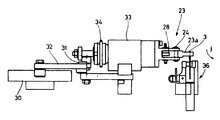
나아가서, 상기 용접부(W)에 있어서 알루미늄선(1)과 CP선(2)의 용접을 한 다음에 알루미늄선(1)의 부분을 이재용 척부재(23)로 고정할 수 있도록 되어 있다. 이재용 척부재(23)는 제6도 및 제7도에 나타낸 바와 같이 상하게 한 쌍의 척집게(23a), (23a)를 지녔으며, 각 척집게(23a)는 축(24)를 중심으로 하여 상하방향으로 요동할 수 있도록 되어 있다. 그리고, 척 집게(23a), (23a) 사이에는 보통 때에는 척개방 상태로 되도록 가압하는 척개방용 스프링(25)이 설치되어 있으며, 또 스프링(25)에 저항하여 척집게(23a)를 폐쇄시키기 위하여 척작동용 스프링(16)에 가압되 압동구(17)가 로울러(28), (29)에 맞닿는 상태에서 설치되어 있다. 압동구(27)에는 로드(29)가 연속 설치되어 있고, 로드(29)의 타단에는 캠(30)에 의하여 회동축(31)을 중심으로 하여 회전운동하게 되는 레버(32)가 맞닿고 있다. 나아가서, 척집게(23a), (23a)는 회전운동드럼(33)에 연결되어 있으며, 회전운동드럼(33)은 도면에 없는 캠기구에 의하여 구동되는 구동벨트(34)에 의하여 180°왕복 회전운동 하게 되어 이재용 척부재(23)에 의하여 물린 탭단자 구성체(3)를 반전시킬 수 있도록 되어 있다.Furthermore, after welding the aluminum wire 1 and the CP wire 2 in the said welding part W, the part of the aluminum wire 1 can be fixed with the transfer material chuck member 23. As shown in FIG. As shown in Figs. 6 and 7, the chuck member 23 for the transfer material has a pair of chuck pliers 23a and 23a, and each chuck claw 23a is centered on the shaft 24. It is possible to swing in the vertical direction. A chuck opening spring 25 is provided between the chuck tongs 23a and 23a to normally open the chuck, and closes the chuck tongs 23a against the spring 25. In order to press the spring 16 for the chuck operation, the pressure port 17 is installed in contact with the rollers 28 and 29. The rod 29 is continuously installed in the pressure port 27, and the lever 32 which rotates about the rotation shaft 31 by the cam 30 abuts on the other end of the rod 29. . Furthermore, the chuck tweezers 23a, 23a are connected to the rotary motion drum 33, and the rotary motion drum 33 is rotated 180 ° by the drive belt 34 driven by a cam mechanism not shown in the drawing. It is to be able to reverse the tab terminal structure (3) bitten by the chuck member 23 for the transfer material.

전술한 바와 같이 하여 탭단자 구성체(3)가 이재용 척부재(23)에 따라 180°반전되었을 때에 제8도 및 제9도에 나타낸 바와 같이 탭단자 구성체의 리이드부(3b)는 인덱스 테이블(35)에 장착된 여러 개의 반소용 척부재(36)(도면에서는 8개의 전송용 척부재를 뜻한다)에 고정되도록 되어 있다. 이 반송용 척부재(36)는 탭단자 구성체(3)의 리이드부(3)를 좌우로부터 끼우는 한 쌍의 척부(36a), (36b)를 지녔으며, 한쪽 척부(36a)의 아암(37)은 좌우방향으로는 이동하지 않도록 유지된 고정척부를 구성하고, 다른쪽 척부(36b)는 움직일 수 있는 척부로, 이 척부(36b)는 아암(38)에 장착한 축(39)을 중심으로 하여 수평방향으로 회전 운동할 수 있는 척개방레버(40)에 부착되었으며, 이 척개방레버(40)는 스프링(41)의 작용에 따라서 항시 고정축의 척부(63a)에 맞닿는 방향으로 가압되어 있다.As described above, when the tab terminal structure 3 is inverted by 180 ° according to the transfer chuck member 23, as shown in FIGS. 8 and 9, the lead portion 3b of the tab terminal structure has an index table 35. As shown in FIG. It is fixed to a plurality of semi-chuck element 36 (in the drawing, eight transmission chuck members) mounted on the). The conveying chuck member 36 has a pair of chuck portions 36a, 36b which pinch the lead portion 3 of the tab terminal structure 3 from left and right, and has an arm 37 of one chuck portion 36a. Is a fixed chuck which is held so as not to move in the left and right directions, and the other chuck 36b is a movable chuck, and the chuck 36b is centered on the shaft 39 mounted on the arm 38. It is attached to the chuck open lever 40 capable of rotating in the horizontal direction, the chuck open lever 40 is always pressed in the direction in contact with the chuck portion 63a of the fixed shaft in accordance with the action of the spring (41).

또 척개방 레버(40)에는 제10도에 나타낸 바와 같이 작동 로울러(42)가 드리워 설치되어 있으며, 인덱스 테이블(35)이 회전운동하여 작동 로울러(42)가 이재용 척부재(23)와 대면하는 위치에 배치하였을 때에 그것과 맞닿는 작동부재 (도면에 없음)에 따라 작동 로울러(42)가 눌려 움직여져서 척개방 레버(40)를 스프링(41)에 저항하여 축(39)을 중심으로 회전운동 하여 척부(36b)를 척부(36a)로부터 이간시킨 척개방 위치로 되게 할 수 있는 구성으로 되어 있다. 나아가서, 이것들 각 척부(36a) 및 (36b)를 지지하는 아암(37), (38)은 수평축(43)에 끼워져서 상하방향으로 회전운동이 가능하도록 되어 있다. 그리고, 이것들 아암(37), (38)에는 돌기(44)가 연설되어 있으며, 돌기(44)는 보통때는 스프링(45)에 가압된 돌자(突子)(46)에 따라 상방으로 향하여 가세하도록 되어 있으며, 이런 상태에서 그 아암(37), (38)에 연결한 고정부품(47)이 인덱스 테이블(35)의 표면(35a)과 맞닿음에 따라 위치 결정되며, 반송용 척부재(36)가 프레스부(P)에 위치하였을 때에는 전술한 돌자(46)을 스프링(45)에 저항하는 방향으로 눌러 움직이게 하여 아암(37), (38)을 돌기(44)가 돌자(46) 위에 맞닿는 상태까지 수평축(43)을 중심으로 하여 하방으로 회전운동하도록 되어 있다.In addition, as shown in FIG. 10, the chuck opening lever 40 is provided with an operation roller 42, and the index table 35 rotates so that the operation roller 42 faces the chuck member 23 for the transfer material. When placed in position, the actuating roller 42 is pushed and moved along the actuating member (not shown) in contact with it, and the chuck opening lever 40 is rotated about the axis 39 against the spring 41, It is the structure which can be made into the chuck opening position which separated the chuck | zipper part 36b from the chuck | zipper part 36a. Further, the arms 37 and 38 which support these chucks 36a and 36b are fitted to the horizontal shaft 43 so as to enable rotational movement in the vertical direction. And these arms 37 and 38 are protruded 44, and the projections 44 are urged upwards in accordance with the projection 46 pressurized by the spring 45 normally. In this state, the fixed parts 47 connected to the arms 37 and 38 are positioned as they come into contact with the surface 35a of the index table 35, and the conveying chuck member 36 is disposed. Is located in the press portion P, the above-described projection 46 moves in a direction against the spring 45 to move the arms 37 and 38 so that the projection 44 abuts on the projection 46. It is designed to rotate downward about the horizontal axis 43 until now.

전술한 바와 같이, 반송용 척부재(36)에 물린 탭단자(3)는 인덱스 테이블(35)이 일정각도(본 실시예에 있어서는 45°)씩 회전함에 따라 프레스부(P)에 까지 반송된다. 프레스부(P)에는 제11도에 나타낸 바와 같이 하부 펀치(48)와, 이 하부펀치(48)의 상방에 설치된 상부펀치(49)로 된 프레스 부재가 설치되어 있으며, 상기 상부펀치(49)는 캠등의 승강구동부재에 의하여 승강하도록 되어 있다. 또, 상부펀치(49)의 둘레이는 프레스된 탭단자 구성체(3)의 탭형성부(3a)가 일정한 형상으로 되도록 정형하기 위한 정형부재(50)가 설치되어 있으며, 이 정형부재(50)는 상부펀치(49)에 의하여 프레스를 할 때에는 상부펀치(49)와 함께 하강하고, 프레스가 완료한 다음에도 더욱 하강을 계속하여 편평하게 되도록 가압 변형된 탭형성부(3a)에 대하여 그것이 일정한 형상이 되도록 정형 가공할 수 있도록 되어 있으며, 이 때문에 정형부재(50)는 상부펀치(49)와는 별개로 그 위에 이것과 동기(同期)하여 구동하도록 되어 있다.As described above, the tab terminal 3 bitten by the conveying chuck member 36 is conveyed to the press section P as the index table 35 rotates by a predetermined angle (45 ° in this embodiment). . As shown in FIG. 11, the press part P is provided with the lower punch 48 and the press member which consists of the upper punch 49 provided above the lower punch 48, The said upper punch 49 The lifting and lowering is performed by lifting members such as cams. Moreover, the shaping | molding member 50 for shaping | molding so that the tab formation part 3a of the pressed tab terminal structure 3 may become a fixed shape is provided in the periphery of the upper punch 49, The shaping | molding member 50 is When pressing by the upper punch 49, it is lowered with the upper punch 49, and it has a constant shape with respect to the press-formed portion 3a that is deformed to continue to descend even more even after the press is completed. The shaping member 50 can be shaped as much as possible. For this reason, the shaping member 50 is driven in synchronization with the upper punch 49 separately therefrom.

여기에서, 공작물(3)은 반송용 척부재(36)에 이하여 하부펀치(48)의 상면보다 높은 위치에 지지된 상태에서 프레스부(P)에 반입하게 되어 하부펀치(48)에 대면하는 위치에 도달하였을 때에는 하부펀치(48)의 하방 위치에 설치한 해제용 푸셔(51)가 실린더, 솔레노이드 등의 구동수단에 따라 수평방향으로 돌출하도록 되어 있다. 상기 해제용 푸셔(51)가 돌자(46)가 스프링(45)에 저항하는 방향으로 압동하고, 반송용 척부재(36)의 지지를 해제하여 아암(37), (38)을 돌기(44)가 돌자(46)의 플랜지부(46a)로부터 떨어져서 그 주동부(周胴部)(46b) 위에 맞닿는 상태까지 수평축(43)을 중심으로 하여 하방으로 회전 운동시켜서 반송용 척부재(36)가 하강하며, 그것에 물린 공작물(3)의 태형성부(3a)를 하부 펀치(48)에 맞닿는 위치에 변위하게 할 수 있도록 되어 있다.Here, the workpiece 3 is brought into the press portion P in a state in which it is supported at a position higher than the upper surface of the lower punch 48 following the conveying chuck member 36, and faces the lower punch 48. When the position is reached, the release pusher 51 provided below the lower punch 48 protrudes in the horizontal direction in accordance with a driving means such as a cylinder or a solenoid. The release pusher 51 is pushed in the direction in which the protrusion 46 resists the spring 45, and releases the support of the conveying chuck member 36 to turn the arms 37 and 38 into the projection 44. The conveyance chuck member 36 is lowered by rotating downwardly about the horizontal axis 43 until it is separated from the flange portion 46a of the projection 46 and abuts on the main drive portion 46b. It is possible to displace the formation part 3a of the workpiece | work 3 bitten | blocked in the position which abuts the lower punch 48.

나아가서, 인덱스 테이블(35)에 있어서의 프레스부(P)의 하류측의 위치에는 전술한 바와 같이 하여 형성한 탭단자를 배출하는 배출부(R)가 설치되어 있다. 이 배출부는 제12도에 나타낸 바와 같이 탭단자(T)를 미끄러져 내리게 하는 슈우트(chute)(52)와, 이 슈우트(52)로부터 공급되는 탭단자(T)를 수용하여 그 방향성을 일치하게 하기 위한 정렬부(53)와, 이 정렬부(53)로부터 공급되는 탭단자(T)를 일정수 수납하는 수납상자(54)를 구비하는 구성으로 되어 있다. 정렬부(53)에는 상단이 개구하여 탭단자(T)가 투입되는 투입구를 지녔으며, 하단이 개폐할 수 있는 배출부로 된 정렬용기(55)를 지녔고, 정렬용기(55)의 양측에는 전자석(56a), (56b)이 서로 이극(異極)이 대면하는 상태로 하여 대향 배서되어 있으며, 이에 따라서 정렬용기(55) 내에 탭단자(T)의 축선방향으로 향하여 자력선을 형성할 수 있도록 되어 있다. 그리고, 정렬용기(55) 내에 투입된 탭단자(T)는 상기 자력선의 작용에 따라 정렬한 상태로 지지되어서 정렬용기(55)내에 일정수의 탭단자(T)가 투입되면 정렬용기(55)가 하강하여 수납상자(54)내에 들어가서 그 하단부를 개방함에 따라 수납상자(54)내에 탭단자(T)를 정렬시킨 상태에서 수납할 수 있도록 되어 있다.Furthermore, the discharge part R which discharges the tab terminal formed as mentioned above is provided in the position of the downstream side of the press part P in the index table 35. As shown in FIG. As shown in FIG. 12, the discharge part accommodates a chute 52 for sliding down the tab terminal T, and a tab terminal T supplied from the chute 52, thereby providing a directivity thereof. It has a structure provided with the alignment part 53 for making it match, and the storage box 54 which accommodates predetermined number of tab terminals T supplied from this alignment part 53. As shown in FIG. The alignment portion 53 has an opening for opening the upper end of the tap terminal (T) is introduced, the lower end has an alignment container (55) as the discharge portion that can be opened and closed, and both sides of the alignment vessel 55 56a) and 56b are opposed to each other in a state where the two poles face each other, whereby magnetic lines of force can be formed in the alignment vessel 55 in the axial direction of the tab terminal T. . Then, the tab terminal T inserted into the alignment container 55 is supported in an aligned state according to the action of the magnetic force line, and when the predetermined number of tap terminals T are introduced into the alignment container 55, the alignment container 55 is inserted. As it descends and enters the storage box 54 and opens its lower end portion, it is possible to store it in a state where the tab terminal T is aligned in the storage box 54.

또, 탭단자(T)는 탭형성부(3a)의 부피가 큰 평판상의 부분에서 리이드부(3b)가 지름이 작은 선상부재로 되어 있으므로 수납상자(54)내에 모두 동일한 방향으로 수납시키면 부분적으로 부풀어 나오게 된다. 따라서, 정렬부(53)에 탭단자(T)를 수납시킬 경우에 있어서 그것을 적당히 그 방향을 반전시킬 필요가 있다. 이 때문에 슈우트(52)의 입구에는 로우터리 솔레노이드(57)에 의하여 수평방향으로 회전 운동하게 되는 공작물 반전 바아(58)가 설치되어 있으며, 이 공작물 반전 바아(57)가 슈우트(52)의 입구에 면하는 상태로 변위하였을 때에는 반송용 척부재(36)로부터 탭단자(T)가 이탈하면 그 탭형성부(3a)와 리이드부(3b)의 연설부분에 하방으로부터 맞닿아서 그것을 반전시킬 수 있도록 되어 있다.In addition, since the tab terminal T is a linear member having a small diameter in the bulky flat portion of the tab forming portion 3a, if the tab terminal T is stored in the same direction in the storage box 54, the tab portion T is partially. It swells out. Therefore, when storing the tab terminal T in the alignment part 53, it is necessary to reverse the direction suitably. For this reason, a workpiece reversing bar 58 is provided at the inlet of the chute 52 to rotate in the horizontal direction by the rotary solenoid 57, and the workpiece reversing bar 57 is provided at the chute 52. When displaced in the state facing the inlet, if the tab terminal T is detached from the conveying chuck member 36, it is brought into contact with the lower part of the tab forming portion 3a and the lead portion 3b from below to reverse it. It is supposed to be.

상술한 공급부(S), 용접부(W), 프레스부(P) 및 배출부(R) 중, 용접부(W)와 프레스부(P)는 그 사이에 탭단자 구성체(3)을 옮겨 싣는 이재용 척부재(23)와 함께 장치 본체(60)에 유닛화한 상태로 하여 설치되어 있으며, 또 이 장치 본체(6)에는 공급부(S)와 배출부(R)가 부설되어 있다. 따라서, 장치 전체 구성의 소형화, 콤팩트화를 도모할 수 있게 된다.Of the above-mentioned supply part S, welding part W, press part P, and discharge part R, the welding part W and the press part P carry out the chuck for transfer materials which carry the tab terminal structure 3 between them. It is provided in the state which united with the member 23 in the apparatus main body 60, and the supply part S and the discharge part R are attached to this apparatus main body 6. As shown in FIG. As a result, the size and compactness of the overall structure of the apparatus can be achieved.

그런데, 탭단자는 콘덴서를 구성하는 것이기 때문에 리이드부의 길이가 다른 한쌍의 탭단자(T1), (T2)를 형성할 필요가 있다. 이와같이, 리이드부의 길이가 다른 한 쌍의 탭단자(T1), (T2)를 단일한 장치로 형성할 수 있도록 하기 위하여 레버(15)에 의한 CP선(2)의 이송량은 2단계로 변화하도록 되어 있다. 그리고, 이와 같이 하여 이송량을 바꾸어도 프레스부(P)에 있어서의 하부 펀치(48)위에 확실하게 탭단자 구성체(3)의 탭형성부(3a)가 위치하도록 하지 않으면 안된다. 그래서, 장치 본체(60)에 있어서 프레스부(P)를 구성하는 각 부재, 인덱스 테이블 및 이재용 척부재(23)는 고정부(61) 위에 설치되어 있으나, 용접부(W)를 구성하는 각 부재는 가동유닛(62)에 설치되어 있고, 가동유닛(62)은 제1도에서 화살표로 나타낸 바와 같이 고정부(61)에 근접·이간하는 방향으로 왕복 이동하게 할 수 있도록 되어 있다. 그리고, 상기 가동유닛(62)을 이동시키기 위하여 제13도에 나타낸 바와 같이, 가동 유닛(62)에는 이송나사(63)가 연결되어 있으며, 이 이송나사(63)는 장치 본체(60)에 설치한 조작핸들(64)에 연설되어서 그 조작핸들(64)을 수동으로 회전시킬 수 있도록 되어 있다.However, since the tab terminal constitutes a capacitor, it is necessary to form a pair of tab terminals T1 and T2 having different lengths of the lead portion. In this way, the feed amount of the CP line 2 by the lever 15 is changed in two stages so that the pair of tab terminals T1 and T2 having different lengths of the lead portion can be formed as a single device. have. And even if the feed amount is changed in this way, the tab formation part 3a of the tab terminal structure 3 must be positioned reliably on the lower punch 48 in the press part P. As shown in FIG. Therefore, in the apparatus main body 60, each member constituting the press portion P, the index table, and the transfer material chuck member 23 are provided on the fixing portion 61, but each member constituting the welding portion W is It is provided in the movable unit 62, and the movable unit 62 is made to be made to reciprocate in the direction approaching and separating from the fixed part 61, as shown by the arrow in FIG. In addition, as shown in FIG. 13 to move the movable unit 62, a transfer screw 63 is connected to the movable unit 62, and the transfer screw 63 is installed in the apparatus main body 60. It is addressed to one operation handle 64 so that the operation handle 64 can be manually rotated.

여기에서, 탭단자의 제조를 원활하게 하기 위하여는 용접으로부터 프레스에 이르기까지의 각 작동부재는 확실하게 동기한 상태에서 작동시킬 필요가 있다. 이러기 위하여, 제14도에 나타낸 바와같이 상술한 각 작동부재는 모우터(65)에 의하여 구동되도록 되어 있다. 그리고, 고정부(61)에 설치된 각 작동부재를 구동시키기 위하여 제1주축(66)이 설치되어 있으며, 또 가동유닛(62)에 장착한 각 작동부재를 구동시키기 위하여 제2주축(67)이 가동유닛(62)에 설치되어 있다. 이것을 제1, 제2의 각 주축(66), (67)을 회전시키기 위하여 모우터(65)와 제1주축(66) 사이 및 제1주축(66)과 제2주축(58) 사이에는 각기 동력전달용 체인(68), (69)이 감겨져 설치되어 있다.Here, in order to smoothly manufacture the tab terminal, it is necessary to operate each of the operating members from welding to the press in a surely synchronized state. To this end, as shown in FIG. 14, each of the above-mentioned operating members is driven by the motor 65. As shown in FIG. In addition, a first spindle 66 is installed to drive the respective operation members installed on the fixing part 61, and a second spindle 67 is provided to drive the respective operation members mounted on the movable unit 62. It is installed in the movable unit 62. This is rotated between the motor 65 and the first spindle 66 and between the first spindle 66 and the second spindle 58 to rotate the first and second spindles 66 and 67, respectively. The power transmission chains 68 and 69 are wound and installed.

본 실시예에 상술한 바와 같이 구성되는 것으로 다음에 그 작동에 대하여 설명한다.It is constructed as described above in the present embodiment and the operation thereof will be described next.

먼저, 제3도에 나타낸 바와 같이 레버(14), (15)를 작동시킴에 따라서 보올클램프(8), (9)를 화살표(a), (b)로 나타낸 방향으로 이동시킴에 따라서 알루미늄선(1) 및 CP선(2)을 각기 알루미늄선 다이(16) 및 CP선 노즐(19)에서 끌어낸다. 여기에서, 알루미늄선(1) 및 CP선(2)은 탭단자 구성체(3)을 형성하였을 경우에 있어서의 탭형성부(3a) 및 리이드부(3b)의 길이치수에 상당하는 양만큼 끌어내도록 하지만, CP선(2)을 끌어낼 때에 그 선단은 CP선 커터(22)의 설치위치에 배치하게 된다. 더욱이, 이와같이 보올클램프(8), (9)의 전진에 따라서 알루미늄선(1) 및 CP선(2)이 끌려나온 다음에 나중에 설명하는 용접이 완료하여 CP선(2)의 절단이 완료하기까지 동안에 보올클램프(8), (9)는 화살표 (a), (b)와는 반대방향으로 이동하여 본래의 상태로 복귀한다.First, as shown in FIG. 3, as the levers 14 and 15 are operated, the aluminum clamps are moved by moving the bowl clamps 8 and 9 in the directions indicated by the arrows a and b. (1) and CP line 2 are pulled out from aluminum wire die 16 and CP line nozzle 19, respectively. Here, the aluminum wire 1 and the CP wire 2 are pulled out by an amount corresponding to the length dimension of the tab forming portion 3a and the lead portion 3b when the tab terminal structure 3 is formed. However, when the CP line 2 is pulled out, its tip is arranged at the installation position of the CP line cutter 22. Furthermore, the aluminum wire 1 and the CP wire 2 are pulled out along the advancement of the bowl clamps 8 and 9 in this manner, and then the welding described later is completed until the cutting of the CP wire 2 is completed. In the meantime, the bowl clamps 8 and 9 move in the opposite directions to the arrows a and b to return to their original states.

다음에, 용접용 척부재(18)가 화살표 (c) 방향으로 작동하여 알루미늄선 다이(16)로부터 돌출한 알루미늄선(1)을 파악하고 커터(17)가 도면중의 화살표 (d) 방향으로 이동하여 알루미늄선(1)의 절단을 한 다음 원래의 위치에 복귀한다. 그리하여, CP선 커터(22)를 작동시켜서 이 CP선 커터(22)에 있어서의 2개의 회전날개(221a), (221b)를 서로 반대방향으로 회전시킴에 따라서 맞대기 용접(butt welding)을 원활하게 하기 위하여 CP선(2)의 선단이 뾰죽한 상태로 되도록 절단하여 둔다.Next, the welding chuck member 18 operates in the direction of arrow c to grasp the aluminum wire 1 protruding from the aluminum wire die 16, and the cutter 17 moves in the direction of arrow d in the figure. It moves and cuts the aluminum wire 1, and returns to an original position. Thus, the butt welding is smoothly performed by operating the CP line cutter 22 to rotate the two rotary blades 221a and 221b in the CP line cutter 22 in opposite directions. In order to cut the tip of the CP line (2) so that it becomes a pointed state.

그런 다음, 용접용 척부재(18)를 화살표 (f) 방향으로 이동시켜서 일정한 길이로 절단된 탭형성부(3a)를 구성하는 알루미늄선(1)을 CP선(2)에 대면하는 위치까지 이행시킨다. 이와 동시에 요동레버(20)를 화살표 (a)와 리이드부(3b)를 지닌 탭단자(T)를 제조할 수 있다.Then, the welding chuck member 18 is moved in the direction of the arrow f to shift the aluminum wire 1 constituting the tab forming portion 3a cut to a constant length to the position facing the CP wire 2. Let's do it. At the same time, the tab lever T having the swing lever 20 with the arrow a and the lead portion 3b can be manufactured.

이와 같이 하여 제조된 탭단자(T)는 인덱스 테이블(35)이 회전 운동하여 배출부(R)에 이행하는 반송용 척부재(36)에 의한 척이 해제되어서 탭단자(T)는 슈우트(52)에 낙하시키게 된다. 그리고, 탭단자(T)는 자체의 무게에 따라 슈우트(52)를 미끄러져 내려가서 정렬부(53)에 있어서의 정렬용기(55)내에 투입된다. 그리하여 , 정렬용기(55)의 양측에 설치된 전자석(56a), (56b)을 여자상태로 함에 따라 그 동안의 자계의 작용에 따라서 그 방향성이 가지런하게 된다. 그리고, 정렬용기(55)내에 일정수의 탭단자(T)가 정렬되면 전자석(56a), (56b)이 소자되어 상기 정렬용기(55)가 수납부로서의 수납상자(54)내에 잠입하는 상태로 하강하여 그 하단부를 개방함에 따라서 탭단자(T)를 수납상자(54)에 정렬시킨 상태로 수납할 수 있게 된다. 또, 공작물 반전 바아(58)를 반송용 척부재(36)에서 슈우트(52)로의 탭단자(T)의 낙하 궤적 내에 면하는 위치에 변위시키면 탭단자(T)는 그 탭부와 리이드부의 연속 설치부분이 공작물 반전 바아(58)와 맞닿아서 반전하게 되며, 수납 상자(54)내에는 탭단자(T)를 그 탭부가 한쪽을 향한 상태의 것과 이것과는 반대쪽을 향한 상태로 된 것과를 대략 같은수 수납 할 수 있게 되어서 부분적으로 부풀어오른다거나 하는 일이 없이 콤팩트하게 수납 할 수 있도록 된다.The tab terminal T manufactured in this way is released by the chuck member 36 for conveyance, in which the index table 35 rotates and shifts to the discharge portion R, so that the tab terminal T is a chute ( 52). And the tab terminal T slides down the chute 52 according to the weight of itself, and is inserted into the alignment container 55 in the alignment unit 53. Thus, as the electromagnets 56a and 56b provided on both sides of the alignment container 55 are excited, their directivity becomes neat according to the action of the magnetic field. Then, when a predetermined number of tab terminals T are aligned in the alignment vessel 55, the electromagnets 56a and 56b are demagnetized so that the alignment vessel 55 is infiltrated into the storage box 54 as a storage portion. As it descends and opens its lower end, the tab terminal T can be stored in a state aligned with the storage box 54. Further, when the work reversing bar 58 is displaced to a position facing the drop trajectory of the tab terminal T from the conveying chuck member 36 to the chute 52, the tab terminal T is continuous with the tab portion and the lead portion. The installation part is in contact with the work reversing bar 58 to be reversed, and in the storage box 54, the tab terminal T is in a state where the tab is facing one side and the opposite side thereof. It becomes possible to store approximately the same number and to be able to store it compactly without swelling partially.

상술한 작업을 순차 반복함에 따라서 연속적으로 탭단자(T)의 제조를 할 수 있게 된다.By sequentially repeating the above operations, it is possible to manufacture the tab terminal T continuously.

그리고, 용접부(W)에서 용접되어서 CP선(2)의 절단을 하기 전에 이재용 척부재(23)로 물려서 CP선(2)이 절단됨에 따라서 탭단자 구성체(3)가 절단 분리됨과 동시에 이재용 척부재(23)을 180°회전운동시킴에 따라 인덱스 테이블(35)에 설치한 반송용 척부재(36)에 이재하여 반송용 척부재(36)에 물린 그대로의 상태에서 프레스부(P)에 반송시켜서 프레스를 하도록 하였으므로 용접부분의 형상과는 관계없이 극히 고속으로, 더욱이 안정한 상태에서 탭단자(T)의 제조를 할 수 있어 그 제조 효율이 현저히 향상한다.Then, before the CP line 2 is welded by the welding portion W and the CP line 2 is cut, the tap terminal member 3 is cut and separated as the CP line 2 is cut, and at the same time, the chuck member for the transfer is cut. As the 23 is rotated 180 degrees, it is transferred to the press chuck member 36 provided on the index table 35 and conveyed to the press section P in a state of being bitten by the conveying chuck member 36. Since the press is made, the tab terminal T can be manufactured at a very high speed and in a stable state irrespective of the shape of the welded portion, and the manufacturing efficiency is remarkably improved.

또, 용접부(W)와 프레스부 사이에 이재용 척부재(23)를 기재시키도록 하고 있으므로, 용접부(W)에서 프레스부(P)로의 옮겨 싣는 것을 하기 위한 기구가 간략화됨에 따라 장치를 소형화, 콤팩트화 할 수 있도록 된다.Moreover, since the chuck member 23 for transfer materials is described between the welding part W and the press part, the apparatus for making it carry out from the welding part W to the press part P is simplified, and the apparatus is compact and compact. It will make you mad.

나아가서, 반송용 척부재(36)로 공작물(3)을 물린 상태 그대로 그 탭구성체(3a)를 성형하도록 되어 있으므로, 고속으로 높은 효율로 탭구성체(3a)의 성형을 할 수 있는 동시에, 탭형성부(3a)를 하부펀치(48)에서 대략 수평으로 되도록 하여 맞닿게 한 상태에서 프레스할 수 있으므로 상하로부터 균일한 가압력을 작용시킬 수 있어서 확실하에 탭형성부(3a)의 중앙부분을 편평하게 되도록 프레스할 수 있도록 되어 고정밀도의 제품을 형성할 수 있게 된다.Furthermore, since the tab structure 3a is molded as it is by biting the workpiece 3 by the conveying chuck member 36, the tab structure 3a can be formed at high speed and with high efficiency, and at the same time, the tab formation is performed. Since the portion 3a can be pressed in a state where it is brought into contact with the lower punch 48 substantially horizontally, a uniform pressing force can be applied from above and below, so that the center portion of the tab forming portion 3a can be made flat. It can be pressed to form a high-precision product.

또한, 리이드부(3b)의 길이가 다른 한 쌍의 탭단자(T1), (T2)를 형성할 필요가 있으나, 길다란 리이드부(3b)를 지닌 탭단자(T1)를 제조하려면 조작핸들(64)을 조작하여 가동유닛(62)을 고정부(61)에서 이간시켜 이것과 함께 레버(15)에 의한 CP선(2)의 이송량을 길게 하고, 또 짧은 리이드부(3b)를 지닌 탭단자(T2)를 제조하려면 조작핸들(55)에 의하여 가동유닛(62)을 고정부(61)에 근접시킴과 동시에 레버(15)에 의한 CP선(2)의 이송량을 짧게 한다. 이에 따라서, 리이드부(3b)의 길이가 바뀌어도 용접부(W)에 의하여 형성되는 탭단자 구성체에 있어서의 탭형성부(3a)의 선단이 일정한 위치까지 송출하게 되어 이재용 척부재(23)에 의한 탭단자 구성체(3)의 척위치는 항상 일정하게 되어, 이 때문에 이재용 척부재(23)을 반전시켜서 탭단자 구성체(3)를 인덱스 테이블(35)에 장착한 반송용 척부재(36)에 옮겨 실었을 때에 탭단자 구성체(3)의 탭형성부(3a)의 위치는 일정하게 된다. 따라서 인덱스 테이블(35)를 회전시켜서 프레스부(P)에까지 반송시켰을 때에 리이드부(3b)의 길이치수가 바뀌어도 탭형성부(3a)를 확실하게 하부펀치(48)의 위치에 배치할 수 있게 된다.In addition, although it is necessary to form a pair of tab terminals T1 and T2 having different lengths of the lead portion 3b, in order to manufacture the tab terminal T1 having the long lead portion 3b, the operation handle 64 ), The movable unit 62 is separated from the fixing unit 61 to increase the conveyance amount of the CP line 2 by the lever 15, and the tab terminal having the short lead portion 3b. In order to manufacture T2), the movable handle 62 is brought close to the fixed portion 61 by the operation handle 55, and the conveyance amount of the CP line 2 by the lever 15 is shortened. Accordingly, even if the length of the lead portion 3b is changed, the tip of the tab forming portion 3a in the tab terminal structure formed by the weld portion W is sent out to a predetermined position, and the tab by the chuck member 23 for the transfer material The position of the chuck of the terminal constructive body 3 is always constant. Therefore, the chuck member 23 for the transfer material is inverted and the tab terminal constructive body 3 is transferred to the conveying chuck member 36 mounted on the index table 35. The position of the tab formation part 3a of the tab terminal structure 3 becomes constant at the time of the following. Therefore, when the index table 35 is rotated and conveyed to the press part P, even if the length dimension of the lead part 3b changes, the tab formation part 3a can be reliably arrange | positioned in the position of the lower punch 48. FIG. .

그러나, 전술한 바와 같이 가동유닛(62)을 이동시켰을 때에 있어서는 용접부(W)를 구성하는 각 작동부재를 구동하는 제1주축(66)과 제2주축(67) 사이에 체인(69)이 감겨서 설치되어 있으며, 이 때문에 체인(69)이 신장하지만 이동량은 탭단자(T1)와 탭단자 (T2)의 길이의 차가 10mm 정도로 좋으므로 그 정도 체인(69)이 신장하여도 격별히 동력의 전달에 지장을 초래하는 일은 없다.However, when the movable unit 62 is moved as described above, the chain 69 is wound between the first spindle 66 and the second spindle 67 for driving the respective operation members constituting the welded portion W. Because of this, the chain 69 is elongated, but the amount of movement is good because the difference between the lengths of the tab terminal T1 and the tab terminal T2 is about 10 mm. It does not interfere with.

이상으로 상세히 설명한 바와 같이, 본 발명에 의하면 용접부와 프레스부는 이들 사이에 이재용 척부재를 개재시켜서 유닛화하여 장치 본체에 설치하도록 하였으므로 간단하고 소형인 이재기구에 의하여 탭단자 구성체를 고속으로 또한 안정한 상태에서 옮겨 실을 수 있게 되어 탭단자의 제조 효율이 극히 향상하며, 그 단위시간당의 제조량을 현저하게 향상시킬 수 있게 되었다.As described in detail above, according to the present invention, the welded portion and the press portion are unitized with a chuck member for transfer therebetween so as to be unitized and installed in the apparatus main body. Since it is possible to carry it on, the manufacturing efficiency of the tap terminal is greatly improved, and the production amount per unit time can be remarkably improved.

Claims (8)

알루미늄선을 일정한 길이로 절단하여 CP선의 선단에 맞닿게 해서 용접한 다음에, CP선을 일정한 길이로 절단함에 따라 탭단자 구성체를 형성하는 용접부와; 그 용접부에서 탭단자 구성체에서의 CP선의 절단하기 전의 상테에서 고정하여 절단후에 180° 회전시킴에 따라 탭단자 구성체를 반전시키는 이재용 척부재와; 상기 인덱스 테이블위에 설치되어 이재용 척부재로부터 탭단자 구성체를 수납하여 상기 인덱스 테이블을 회전시킴에 따라 프레스부에 반입하고, 상기 탭단자 구성체의 알루미늄 선부를 프레스하여 편평하게 되도록 가압 변형시킴과 동시에 일정한 형상으로 정형함으로써 탭형성부를 성형하는 프레스부와; 이 프레스부에서 성형된 탭단자를 수납하는 수납부로 구성한 것을 특징으로 하는 탭단자의 제조 장치.Welding the aluminum wire by cutting the aluminum wire into a predetermined length to abut the tip of the CP wire, and then cutting the CP wire into a predetermined length to form a tab terminal structure; A chuck member for dissimilar material for inverting the tab terminal structure by fixing it in the upper edge before cutting the CP line in the tab terminal structure in the welded portion and rotating the plate 180 degrees after cutting; It is installed on the index table and accommodates the tab terminal member from the transfer material chuck member and brings it into the press section as the index table is rotated, and presses the aluminum wire of the tab terminal member to deform it to be flat and at the same time uniform shape. A press part for shaping the tab forming part by shaping; An apparatus for manufacturing a tab terminal, comprising: an accommodating portion for accommodating a tab terminal molded by the press portion. 제1항에 있어서, 용접부, 프레스부 및 이재용 척부재를 장치 본체에 설치하였으며, 장치 본체에서의 고정부에 용접부를 설치함과 동시에 프레스부 및 이재용 척부재를 가동부에 설치하고, 이 가동부를 공정부에 근접, 이간하는 방향으로 이동할 수 있도록 한 것을 특징으로 하는 탭단자의 제조 장치.The welding part, the press part and the chuck member for the transfer material are installed in the main body of the apparatus, and the press part and the transfer chuck member are installed in the movable part at the same time as the welding part is installed in the fixed part of the apparatus main body. An apparatus for manufacturing a tab terminal, wherein the tab terminal is moved in a direction close to and separated from the government. 제2항에 있어서, 가동부에 있어서의 각 작동부재를 구동하기 위하여 설치된 주축과, 고정부에서의 각 작동부재를 구동하기 위한 주축의 사이에 신축할 수 있는 전달용 체인을 돌려감고, 이 전달용 체인을 회전 구동함에 따라 가동부측의 각 작동부재의 고정측의 작동부재를 동기하여 구동하도록 구성한 것을 특징으로 하는 탭단자의 제조 장치.The transmission chain according to claim 2, wherein the transmission chain which can be stretched and contracted between the main shaft provided for driving each operating member in the movable portion and the main shaft for driving each operating member in the fixed portion is rotated. An apparatus for manufacturing a tab terminal, characterized in that the drive member is configured to synchronously drive the actuating member on the fixed side of each actuating member on the movable part side as the chain is driven to rotate. 제1항에 있어서, 용접부에 설치하게 되는 CP선 커터를 편심회전하여 서로 접속·이간할 수 있는 한 쌍의 회전날개로 형성하도록 구성한 것을 특징으로 하는 탭단자의 제조 장치.2. The apparatus for manufacturing a tab terminal according to claim 1, wherein the CP line cutter provided in the welded portion is formed by a pair of rotary blades that can be eccentrically rotated and connected to each other. 제1항에 있어서, 용접부에서 알루미늄선과 CP선의 용접시에 알루미늄선을 CP선의 축선방향으로 직진하도록 압동하게 구성한 것을 특징으로 하는 탭단자의 제조 장치.The apparatus for manufacturing a tab terminal according to claim 1, wherein the welding portion is configured to press the aluminum wire so that the aluminum wire moves straight in the axial direction of the CP wire during welding of the aluminum wire and the CP wire. 제1항에 있어서, 인덱스 테이블에 탭단자 구성체의 리이드부를 고정하는 척부재를 설치하고, 그 척부재를 상하방향으로 목흔들림이 자유롭도록 하여 프레스부에 탭단자 구성체를 반입할 경우에는 그 프레스부에 있어서의 하부펀치의 상면보다 높은 위치에 지지하고, 하부펀치에 대면하는 위치로 변위하였을 때에 척부재를 하강시켜서 탭단자 구성체를 하부펀치위에 재치하도록 구성한 것을 특징으로 하는 탭단자의 제조 장치.2. The press section according to claim 1, wherein a chuck member for fixing the lead portion of the tab terminal member is provided in the index table, and the chuck member is freely shaken in the vertical direction so that the tab terminal member is brought into the press section. An apparatus for manufacturing a tab terminal, wherein the tab terminal member is mounted on the lower punch by lowering the chuck member when supported at a position higher than the upper surface of the lower punch in the upper punch and displaced to a position facing the lower punch. 제1항에 있어서, 배출부에는 인덱스 테이블에서 배출되는 탭단자를 정렬시키기 위하여 정렬용기를 설치하여 정렬용기의 양측에 한쌍의 전자석을 각기 이극이 대면하는 상태로 설치하고, 이 전자석을 여자함에 따라서 정렬용기내에 탭단자의 축선에 잇따른 방향으로 자력선을 작용시키도록 구성한 것을 특징으로 하는 탭단자의 제조 장치.The method of claim 1, wherein the discharge portion is provided with an alignment vessel for aligning the tab terminals discharged from the index table, and a pair of electromagnets are installed on both sides of the alignment vessel with the two poles facing each other. An apparatus for manufacturing a tab terminal, comprising: a magnetic force line acting in a direction subsequent to the axis of the tab terminal in the alignment vessel. 제7항에 있어서, 배출부에는 인덱스 테이블에서 배출되는 탭단자를 반전시켜서 정렬용기에 도입하기 위한 반전 바아를 탭단자의 탭형성부와 리이드부의 연결부분에 하방으로부터 맞닿는 위치와 탭단자로부터 이간하는 위치 사이에 변위할 수 있도록 설치하는 구성으로 한 것을 특징으로 하는 탭단자의 제조 장치.8. The discharge portion according to claim 7, wherein the discharge portion has a reversal bar for reversing the tab terminal discharged from the index table to introduce the alignment container from a position where the tab contact portion of the tab terminal and the connecting portion of the lead portion are connected downward from the tab portion and the tab terminal. An apparatus for manufacturing a tab terminal, characterized in that the configuration is provided so as to be displaced between positions.
KR1019880002939A 1987-03-20 1988-03-19 Manufacturing apparatus for tab terminal KR940004944B1 (en)

Applications Claiming Priority (3)

Application Number Priority Date Filing Date Title
JP62063976A JPS63232283A (en) 1987-03-20 1987-03-20 Manufacturing apparatus for tab terminal
JP62-63976 1987-03-20
JP63976 1987-03-20

Publications (2)

Publication Number Publication Date
KR880011839A KR880011839A (en) 1988-10-31
KR940004944B1 true KR940004944B1 (en) 1994-06-07

Family

ID=13244822

Family Applications (1)

Application Number Title Priority Date Filing Date
KR1019880002939A KR940004944B1 (en) 1987-03-20 1988-03-19 Manufacturing apparatus for tab terminal

Country Status (2)

Country Link
JP (1) JPS63232283A (en)
KR (1) KR940004944B1 (en)

Families Citing this family (1)

* Cited by examiner, † Cited by third party
Publication number Priority date Publication date Assignee Title
KR101417391B1 (en) * 2012-11-05 2014-07-09 세방전지(주) Strap arrange apparatus of battery

Also Published As

Publication number Publication date
JPS63232283A (en) 1988-09-28
JPH0437569B2 (en) 1992-06-19
KR880011839A (en) 1988-10-31

Similar Documents

Publication Publication Date Title
US4175316A (en) Wire lead clamping mechanism for wire lead production apparatus
US4164808A (en) Apparatus for producing sets of accurately and identically sized wire leads
US4166315A (en) Wire gathering mechanism for wire lead production apparatus
GB1118861A (en) Wire cutting and stripping machine
US3672025A (en) Terminal applicator
US2954599A (en) Lead making apparatus
US4409734A (en) Harness making apparatus and method
KR940004944B1 (en) Manufacturing apparatus for tab terminal
EP0131436B1 (en) Stripping apparatus for stripping coated wire
US3018679A (en) Apparatus for severing electrical leads from a continuous wire source
US3848316A (en) Lead wire assembly apparatus
US4217937A (en) Coil winding machine
US3988092A (en) Apparatus for making retractile cords
CN210403502U (en) Full-automatic coil automatic winding machine
EP0278737A1 (en) Method and apparatus for forming welded rings
SU1191227A1 (en) Line for manufacturing ribbed bimetallic pipes
JPH0581165B2 (en)
US3351103A (en) Apparatus for severing, feeding, and welding a predetermined length of wire
US3704496A (en) Machine for assembling contact sockets for electrical connections of the plug-and-socket type
US4055033A (en) Cam operated compression molding apparatus
KR0128800B1 (en) Process for making cassette spring
CN220880091U (en) Hemming equipment is used in metalwork processing
JPH06290846A (en) Device for crimping terminal of electric wire
JP2529917B2 (en) Ultra-small rectangular coil automatic manufacturing equipment
CN215699604U (en) Spring fastener processing equipment

Legal Events

Date Code Title Description
A201 Request for examination
E902 Notification of reason for refusal
G160 Decision to publish patent application
E701 Decision to grant or registration of patent right
GRNT Written decision to grant
LAPS Lapse due to unpaid annual fee