KR940004824B1 - Slip joint seal assembly - Google Patents
Slip joint seal assembly Download PDFInfo
- Publication number
- KR940004824B1 KR940004824B1 KR1019850009273A KR850009273A KR940004824B1 KR 940004824 B1 KR940004824 B1 KR 940004824B1 KR 1019850009273 A KR1019850009273 A KR 1019850009273A KR 850009273 A KR850009273 A KR 850009273A KR 940004824 B1 KR940004824 B1 KR 940004824B1
- Authority
- KR
- South Korea
- Prior art keywords
- seal
- cage
- slip joint
- shaft
- sealing assembly
- Prior art date
Links
- 238000007789 sealing Methods 0.000 claims description 40
- 239000000314 lubricant Substances 0.000 claims description 11
- 239000010687 lubricating oil Substances 0.000 claims description 6
- 230000036461 convulsion Effects 0.000 claims description 5
- 229920001971 elastomer Polymers 0.000 claims description 3
- 239000000806 elastomer Substances 0.000 claims description 3
- 230000001050 lubricating effect Effects 0.000 claims description 2
- 239000004033 plastic Substances 0.000 claims description 2
- 239000002184 metal Substances 0.000 description 3
- 239000004677 Nylon Substances 0.000 description 1
- 239000000853 adhesive Substances 0.000 description 1
- 230000001070 adhesive effect Effects 0.000 description 1
- 230000000712 assembly Effects 0.000 description 1
- 238000000429 assembly Methods 0.000 description 1
- 239000000356 contaminant Substances 0.000 description 1
- 238000002788 crimping Methods 0.000 description 1
- 230000009977 dual effect Effects 0.000 description 1
- 239000011521 glass Substances 0.000 description 1
- 238000005461 lubrication Methods 0.000 description 1
- 239000000463 material Substances 0.000 description 1
- 229920001778 nylon Polymers 0.000 description 1
- 230000001105 regulatory effect Effects 0.000 description 1
Images

Classifications
-
- F—MECHANICAL ENGINEERING; LIGHTING; HEATING; WEAPONS; BLASTING
- F16—ENGINEERING ELEMENTS AND UNITS; GENERAL MEASURES FOR PRODUCING AND MAINTAINING EFFECTIVE FUNCTIONING OF MACHINES OR INSTALLATIONS; THERMAL INSULATION IN GENERAL
- F16J—PISTONS; CYLINDERS; SEALINGS
- F16J15/00—Sealings
- F16J15/16—Sealings between relatively-moving surfaces
- F16J15/164—Sealings between relatively-moving surfaces the sealing action depending on movements; pressure difference, temperature or presence of leaking fluid
-
- F—MECHANICAL ENGINEERING; LIGHTING; HEATING; WEAPONS; BLASTING
- F16—ENGINEERING ELEMENTS AND UNITS; GENERAL MEASURES FOR PRODUCING AND MAINTAINING EFFECTIVE FUNCTIONING OF MACHINES OR INSTALLATIONS; THERMAL INSULATION IN GENERAL
- F16D—COUPLINGS FOR TRANSMITTING ROTATION; CLUTCHES; BRAKES
- F16D3/00—Yielding couplings, i.e. with means permitting movement between the connected parts during the drive
- F16D3/02—Yielding couplings, i.e. with means permitting movement between the connected parts during the drive adapted to specific functions
- F16D3/06—Yielding couplings, i.e. with means permitting movement between the connected parts during the drive adapted to specific functions specially adapted to allow axial displacement
-
- F—MECHANICAL ENGINEERING; LIGHTING; HEATING; WEAPONS; BLASTING
- F16—ENGINEERING ELEMENTS AND UNITS; GENERAL MEASURES FOR PRODUCING AND MAINTAINING EFFECTIVE FUNCTIONING OF MACHINES OR INSTALLATIONS; THERMAL INSULATION IN GENERAL
- F16D—COUPLINGS FOR TRANSMITTING ROTATION; CLUTCHES; BRAKES
- F16D3/00—Yielding couplings, i.e. with means permitting movement between the connected parts during the drive
- F16D3/84—Shrouds, e.g. casings, covers; Sealing means specially adapted therefor
- F16D3/843—Shrouds, e.g. casings, covers; Sealing means specially adapted therefor enclosed covers
- F16D3/848—Shrouds, e.g. casings, covers; Sealing means specially adapted therefor enclosed covers allowing relative movement of joint parts due to sliding between parts of the cover
-
- F—MECHANICAL ENGINEERING; LIGHTING; HEATING; WEAPONS; BLASTING
- F16—ENGINEERING ELEMENTS AND UNITS; GENERAL MEASURES FOR PRODUCING AND MAINTAINING EFFECTIVE FUNCTIONING OF MACHINES OR INSTALLATIONS; THERMAL INSULATION IN GENERAL
- F16J—PISTONS; CYLINDERS; SEALINGS
- F16J15/00—Sealings
- F16J15/16—Sealings between relatively-moving surfaces
- F16J15/32—Sealings between relatively-moving surfaces with elastic sealings, e.g. O-rings
- F16J15/3204—Sealings between relatively-moving surfaces with elastic sealings, e.g. O-rings with at least one lip
- F16J15/3232—Sealings between relatively-moving surfaces with elastic sealings, e.g. O-rings with at least one lip having two or more lips
Landscapes
- Engineering & Computer Science (AREA)
- General Engineering & Computer Science (AREA)
- Mechanical Engineering (AREA)
- Sealing With Elastic Sealing Lips (AREA)
- Sealing Devices (AREA)
- Joints Allowing Movement (AREA)
- Joints With Pressure Members (AREA)
- Sealing Of Bearings (AREA)
Abstract
내용 없음.No content.
Description
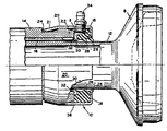
제1도는 본 발명의 바람직한 실시예를 포함하는 슬립 조인트 밀봉 조립체의 부분 단면도.1 is a partial cross-sectional view of a slip joint seal assembly including a preferred embodiment of the present invention.
제2도는 본 발명에 따른 슬립 조인트 밀봉 조립체의 다른 바람직한 실시예를 나타내는 단면도.2 is a cross-sectional view showing another preferred embodiment of a slip joint seal assembly according to the present invention.
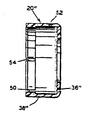
제3도는 바람직한 실시예의 밀봉 조립체의 한 부분을 구성하는 케이지의 다른 실시예를 나타내는 단면도.3 is a cross-sectional view showing another embodiment of a cage constituting a part of the sealing assembly of the preferred embodiment.
* 도면의 주요부분에 대한 부호의 설명* Explanation of symbols for main parts of the drawings
10, 10′: 슬립 조인트 밀봉 조립체 14, 14′: 슬리이브10, 10 ': slip
16, 16′: 스플라인 18, 18′: 밀봉체16, 16 ': Spline 18, 18': Seal
20, 20′, 20″ : 케이지(cage) 24 : 흠20, 20 ′, 20 ″: Cage 24: Hmm
26, 28 : 주 밀봉립 30, 30′: 보조 밀봉립26, 28:
32, 32′: 재급유 체임버 34, 34′: 저어크(Zerk) 이음쇠32, 32 ': refueling
36, 36″ : 반경방향 연장 부분 38, 38″: 축방향 연장 부분36, 36 ″: radially extending
40, 50 : 링40, 50: ring
본 발명은 탄성 중합체로 된 밀봉체를 포함하는 슬립 조인트 밀봉 조립체에 관한 것이다. 더 구체적으로, 본 발명은 그와 같은 밀봉 조립체에 설치된 특별한 윤활 체임버 혹은 공동부에 재급유할 동안 윤활유의 흐름을 조절하기 위한 수단을 가진 상기한 밀봉체에 관한 것이다.The present invention relates to a slip joint seal assembly comprising a seal of elastomer. More specifically, the present invention relates to the aforementioned seal with means for regulating the flow of lubricant during refueling to a special lubrication chamber or cavity installed in such a seal assembly.
재급유 설비의 종래의 밀봉 조립체는 재급유 동안 윤활유가 이탈하지 못하게 효과적으로 밀봉하는데 부적합했었다. 재급유 동안 윤활유의 흐름을 막기 위하여 밀봉립을 사용한 밀봉 조립체에서, 종래 기술의 립들은 축 밀봉면과 항상 접촉을 유지하므로 조기에 마모되어 버린다. 게다가, 그와 같은 밀봉부재들에서는, 때때로 조립체의 주 밀봉립들이 덜 효과적으로 되게 하는 현상이 발생하였다. 예를들어, 그와 같은 밀봉 조립체는 스플라인 결합된 부재들이 서로에 대해서 신장 및 수축될때 탄성 중합 밀봉체가 축을 따라서 전후로 요동함을 실제로 경험하게 된다. 이러한 작동으로 오염물이 보호되지 못한 내부 스플라인 지역으로 들어가게 된다.Conventional sealing assemblies of refueling facilities have been inadequate for sealing effectively so that lubricant cannot escape during refueling. In a seal assembly using seal lips to prevent lubricating oil flow during refueling, the prior art lips wear out prematurely because they always remain in contact with the axial seal surface. In addition, in such sealing members, a phenomenon sometimes occurred that makes the main sealing lips of the assembly less effective. For example, such a sealing assembly actually experiences that the elastomeric seal swings back and forth along an axis when the splined members are stretched and retracted with respect to each other. This operation leads to an internal spline area where contaminants are not protected.
이런 문제는 2중 주 밀봉립을 사용함으로써 해소되기로 하는데, 그것은 결과적으로 주 밀봉립들에 여분의 힘을 가하게 한다. 종래 기술에서, 특히 2중 주 밀봉립을 사용할 수 있는 상황에서 이용할 수 있는 조립체보다 더 개선된 탄성 중합체 밀봉 조립체가 요구된다.This problem is solved by using a double main sealing lip, which results in applying extra force to the main sealing lip. In the prior art, there is a need for an improved elastomeric seal assembly than an assembly that can be used, particularly in situations where a dual main seal lip can be used.
본 발명의 슬립 조인트 밀봉 조립체는 종래 기술의 문제점들을 제거한 크게 개선된 재급유 밀봉 기구를 제공한다. 이 밀봉 조립체는 재급유 체임버 지역쪽으로 각진 탄성 중합체의 보조 밀봉립을 포함한다. 또한, 보조 밀봉립은 평상시에는 축표면과 접촉하지 않고 있다가, 단지 재급유할 동안만 접촉되도록 배치되어 있다.The slip joint sealing assembly of the present invention provides a greatly improved refueling sealing mechanism that eliminates the problems of the prior art. The seal assembly includes an auxiliary seal of elastomeric angled towards the refueling chamber region. In addition, the auxiliary sealing lip is not normally in contact with the axial surface, but is arranged to be in contact only during refueling.
바람직한 형태에서, 이 밀봉 조립체는 환형의 탄성중합 밀봉체와, 반경방향 및 원주방향으로 그 밀봉체를 지지하는 환형의 금속 케이지를 포함한다. 또한, 이 밀봉 조립체는 환형의 재급유 체임버를 가진다. 밀봉체의 내부에는 축과 항상 접촉하도록 배치된 한쌍의 각이져 배향되고 평행한 주 밀봉립이 제공된다. 보조 밀봉립은 재급유 체임버와 통하도록 배치되어 재급유 체임버가 가압될 동안만 축과 접촉된다. 따라서, 이 개선된 밀봉 조립체는 윤활유가 밀봉립들로 흐르지 못하게 작동하며, 그 대신에 원하는 바대로 윤활유가 슬립 스플라인 조인트 지역으로 흐르게 한다.In a preferred form, the seal assembly comprises an annular elastomeric seal and an annular metal cage supporting the seal in the radial and circumferential directions. The sealing assembly also has an annular refueling chamber. The interior of the seal is provided with a pair of angled oriented and parallel main seals arranged to always contact the axis. The auxiliary seal lip is arranged in communication with the refueling chamber and is in contact with the shaft only while the refueling chamber is pressurized. Thus, this improved seal assembly operates to prevent lubricant from flowing into the seal lips, instead allowing the lubricant to flow into the slip spline joint area as desired.
제1도에 도시된 바와 같이, 슬립 조인트 밀봉 조립체(10)는 스터브(stub)축(12)과 슬립 조인트 슬리이브(14) 사이에 윤활 밀봉 접촉면을 제공한다. 그 축(12)은 슬리이브(14)내로 연장되어 있고, 서로 맞물리는 스플라인들(16)에 의해 그 슬리이브에 연결되어 있다. 축(12)은 도시된 바와 같은 연결 요우크(8)를 포함한다.As shown in FIG. 1, the slip
이 밀봉 조립체(10)는 금속 케이지(20)안에 지지되는 탄성 중합체 밀봉체(18)를 포함한다. 케이지는 반경방향 부분(36)과 축방향 부분(38)을 가지며, 축방향 부분(38)에 의해서(이 특정 실시예에서는 크림핑(crimping)에 의해) 슬립 조인트 슬리이브(14)의 단부(22)에 고정된다. 이렇게 하기 위해서, 원주방향으로 연장하는 외부 홈(24)이 슬리이브(14)의 단부(22)에 형성되며, 케이지(20)의 개방 단부(21)가 도시되는 바와 같이 상기 홈(24)속으로 물려진다. 이 밀봉 조립체(10)의 하반부 도면에서, 케이지의 반경방향 및 축방향 부분(36,38)은 밀봉체(18)에 접합되지 않고 밀봉체(18)를 지지하도록 제공된다. 따라서, 본 바람직한 실시예에서는 통상의 접착제 사용이 필요하지 않다.This
밀봉체(18)는 스터브 축(12)의 요우크 단부쪽으로 각이져 배치된 2개의 주 밀봉립들(26,28)을 포함하고, 그 밀봉립들은 축(12)과 항상 접촉하도록 배치된다. 슬립 조인트 슬리이브(14)를 향해 각이져 배치된 보조 밀봉립(30)이 주 밀봉립들(26,28)의 후방에 위치한다. 보조 밀봉립(30)은 축(12)과 평상시 접촉되지 않도록 배치되고, 바람직한 예에서는 축으로부터 4/1000-12/1000인치(0.0102-0.0305㎝)정도 떨어져 있다. 전술한 바와 같이, 보조 밀봉립(30)은 오직 이 밀봉 조립체(10)에 재급유할 동안만 축과 접촉하도록 되어 있고, 환형 재급유 체임버(32)속으로 압입되는 윤활유에 의해서 표면에 압착되게 배치된다. 재급유 체임버는, 케이지(20)의 축방향 부분(38)을 통해 반경방향으로 연장되 통상의 저어크(zerk) 이음쇠(34)에 의해서 윤활유가 압입되는 윤활유 수용 공동부를 형성한다. 원통형의 윤활유 통로(6)는 저어크 이음쇠(34)로부터 재급유 체임버(32)까지 연장된다. 이 밀봉조립체(10)의 상하 절반부를 비교해보면, 재급유 체임버(32)는 대략 환형의 공동부를 형성하고, 상반부에 도시된 바와 같이 윤활유가 유입될 수 있도록 저어크 이음쇠(34)의 통로(6)와 직접 연결됨을 알 수 있다. 재급유 도중 체임버에 압력을 가하면, 보조 밀봉립(30)이 축(12)의 표면에 대해 반경방향 안쪽으로 밀리게 되어 주 밀봉립들(26,28)쪽으로 윤활유가 흐르지 못하게 된다. 대신에, 윤활유는 요구에 따라 스플라인들(16)의 결합 지역으로 역류하게 된다.The seal 18 comprises two
제2도에 슬립 조인트 밀봉 조립체(10′)의 다른 바람직한 실시예가 도시되는데, 이 실시예는 환형 링 혹은 와셔(40)를 제외하고는 제1도의 실시예와 모든 면에서 동일하다. 그 와셔(40)는 저어크 이음쇠(34′)를 통한 재급유중 보조 밀봉립(30′)이 축(12′)과 접촉하게 되도록 밀리는 경향을 높이기 위해 사용된다. 이러한 목적으로, 와셔는 슬리이브(14′)의 단부(22′)의 말단(44)에 위치되어 윤활유의 비교적 낮은 점도 및/또는 슬립 조인트의 단부(22′)의 기하학적 조건하에서 재급유 체임버(32′)의 부피를 제한한다. 이 실시예에서, 슬리이브(14′)는 대단히 경사진 면(42)을 포함하는데, 그 경사진 면(42)이 없다면 윤활유가 스플라인들(16′)의 결합 지역으로부터 쉽게 전환되는 경항이 있다. 와셔(40)는 케이지(20′)에 부착된 것이 아니라 단순히 케이지(20′)에 의해서 안내된다. 바람직한 다른 실시예에서, 와셔(40)의 내경은 축(12′)과 보조 밀봉립(30′) 사이의 간격보다 더 큰 틈새를 제공한다.Another preferred embodiment of the slip joint seal assembly 10 'is shown in FIG. 2, which is the same in all respects to the embodiment of FIG. 1 except for the annular ring or washer 40. FIG. The washer 40 is used to increase the tendency to push the secondary sealing lip 30 'during refueling through the jerk fitting 34' to come into contact with the shaft 12 '. For this purpose, the washer is located at the
제3도는 금속이 아니라 유리충전 나일론(glass-filled nylon) 재료로 구성된 다른 실시예의 케이지(20″)를 도시한다. 앞에서와 같이, 케이지는 반경방향 부분(36″)과 축방향 부분(38″)을 가진다. 그러나, 축방향 부분(38″)은 제1도의 홈(24)과 결합하기 위한 반경방향 안쪽으로 돌출하는 멈춤 링(50)을 일체로 가지고 있다. 저어크 이음쇠는 축방향 스플릿 부분(54)이 케이지(20″)의 플라스틱 몸체를 휘게 하면서 구멍(52)을 통해서 설치될 수 있다.3 shows another
Claims (15)
Applications Claiming Priority (2)
| Application Number | Priority Date | Filing Date | Title |
|---|---|---|---|
| US06/682,121 US4592556A (en) | 1984-12-17 | 1984-12-17 | Slip joint seal assembly |
| US682.121 | 1984-12-17 |
Publications (2)
| Publication Number | Publication Date |
|---|---|
| KR860005170A KR860005170A (en) | 1986-07-18 |
| KR940004824B1 true KR940004824B1 (en) | 1994-06-01 |
Family
ID=24738299
Family Applications (1)
| Application Number | Title | Priority Date | Filing Date |
|---|---|---|---|
| KR1019850009273A KR940004824B1 (en) | 1984-12-17 | 1985-12-10 | Slip joint seal assembly |
Country Status (14)
| Country | Link |
|---|---|
| US (1) | US4592556A (en) |
| JP (1) | JPS61144486A (en) |
| KR (1) | KR940004824B1 (en) |
| AU (1) | AU586842B2 (en) |
| BE (1) | BE903868A (en) |
| BR (1) | BR8506260A (en) |
| CA (1) | CA1266690A (en) |
| DE (1) | DE3542143C2 (en) |
| ES (1) | ES296370Y (en) |
| FR (1) | FR2574892B1 (en) |
| GB (1) | GB2168438B (en) |
| IT (1) | IT1181987B (en) |
| MX (1) | MX162426A (en) |
| SE (1) | SE463433B (en) |
Families Citing this family (23)
| Publication number | Priority date | Publication date | Assignee | Title |
|---|---|---|---|---|
| US4767381A (en) * | 1985-12-30 | 1988-08-30 | Gkn Automotive Components Inc. | Boot restraint for plunging universal joint |
| US4768627A (en) * | 1987-01-23 | 1988-09-06 | Tayco Developments, Inc. | Frictionless hydraulic damper and damper-snubber |
| US5092125A (en) * | 1987-10-29 | 1992-03-03 | Automotive Products Plc | Seal |
| DE8811981U1 (en) * | 1988-09-22 | 1988-11-10 | Bohner, Volker, 2944 Wittmund | Adjustable pipe gland for linear movement and system sealing |
| FR2657408B1 (en) * | 1990-01-22 | 1992-05-15 | Glaenzer Spicer Sa | RETAINING MEMBER OF A SLIDING ANNULAR SEAL IN A TELESCOPIC SYSTEM. |
| IT1241741B (en) * | 1990-06-22 | 1994-02-01 | Edi Bondioli | PROTECTION FOR CARDANIC SHAFTS WITH LUBRICATION VEHICLES |
| US5078533A (en) * | 1991-07-01 | 1992-01-07 | Rockford Powertrain, Inc. | Driveline yoke with improved seal retainer |
| US5299982A (en) * | 1991-08-15 | 1994-04-05 | Burton Robert A | Slip joint seal for a driveshaft |
| US5230658A (en) * | 1992-04-06 | 1993-07-27 | Burton Robert A | Driveshaft with slip joint seal |
| CA2130786A1 (en) * | 1994-06-30 | 1995-12-31 | Robert A. Burton | Driveshaft with sealed slip joint seal |
| US5853177A (en) * | 1996-05-28 | 1998-12-29 | Meritor Heavy Vehicle Systems, Llc | Drive transmission sealing device |
| US5716277A (en) * | 1996-06-10 | 1998-02-10 | Dana Corporation | Seal for a universal joint trunnion |
| US5772520A (en) * | 1996-07-11 | 1998-06-30 | Ford Motor Company | Vented studyoke on slip-between-center driveshaft |
| IT1293125B1 (en) * | 1997-06-18 | 1999-02-11 | Edi Bondioli | GREASER DEVICE FOR A TELESCOPE TRANSMISSION SHAFT |
| US6059663A (en) * | 1998-07-13 | 2000-05-09 | Neapco Inc. | One-piece sealing system for a universal joint assembly |
| US6616146B2 (en) | 2001-12-05 | 2003-09-09 | Caterpillar Inc | Radial seal arrangement |
| DE10234305A1 (en) * | 2002-07-26 | 2004-02-19 | Spicer Gelenkwellenbau Gmbh & Co. Kg | Sealing ring for sealing a length compensation of a cardan shaft |
| US6893350B2 (en) * | 2003-05-08 | 2005-05-17 | American Axle & Manufacturing, Inc. | Universal joint with torsionally-compliant spider assembly |
| US6863613B2 (en) * | 2003-05-13 | 2005-03-08 | Torque Traction Technologies, Inc. | Sealed axially displaceable slip joint |
| JP5708354B2 (en) * | 2011-08-08 | 2015-04-30 | 株式会社アドヴィックス | Coupling device for rotating body connection |
| TR201410151A1 (en) * | 2014-08-29 | 2016-03-21 | Tirsan Kardan Sanayi Ve Ticaret Anonim Sirketi | Seal structure with front scraping feature which prevents separation in sliding set members of cardan shafts |
| JP6367659B2 (en) * | 2014-09-18 | 2018-08-01 | 日立オートモティブシステムズ株式会社 | Power transmission shaft and vehicle propeller shaft |
| USD802104S1 (en) * | 2015-09-25 | 2017-11-07 | Nok Corporation | Seal |
Family Cites Families (16)
| Publication number | Priority date | Publication date | Assignee | Title |
|---|---|---|---|---|
| US2177441A (en) * | 1937-09-13 | 1939-10-24 | Achslager Syndikat | Oil and dust packing for rotating axles or shafts |
| FR880243A (en) * | 1941-03-07 | 1943-03-17 | Freudenberg Carl | Seal for moving machine parts |
| DE877257C (en) * | 1943-06-20 | 1953-05-21 | Holstein & Kappert Maschf | Piston rod seal for bottle pressing devices |
| US3248900A (en) * | 1964-02-13 | 1966-05-03 | Twin Disc Clutch Co | Anti-friction slip joint |
| DE1910284B2 (en) * | 1969-02-28 | 1971-05-19 | PTO SHAFT | |
| BE754143A (en) * | 1969-11-21 | 1971-02-01 | Timken Roller Bearing Co | SOFT LABYRINTH SEAL BEARING ASSEMBLY |
| IT979768B (en) * | 1972-05-05 | 1974-09-30 | Glaenzer Spicer Sa | PROTECTION DEVICE FOR SLIDING CARDAN JOINTS AGAINST DUST AND FOREIGN BODIES |
| FR2183398A5 (en) * | 1972-05-05 | 1973-12-14 | Glaenzer Spicer Sa | |
| GB1407288A (en) * | 1972-11-28 | 1975-09-24 | Anderson Mavor Ltd | Sealing device |
| DE2308820C3 (en) * | 1973-02-22 | 1984-09-20 | Gelenkwellenbau Gmbh, 4300 Essen | Axially movable lip seal for the splined shaft hub of a cardan shaft |
| SE406116B (en) * | 1973-09-27 | 1979-01-22 | Gelenkwellenbau Gmbh | LINKED AXLE WITH ATMINSTONE A RING-SAVE SAVE FOR PLACING BALANCING WEIGHTS |
| US4166628A (en) * | 1974-05-30 | 1979-09-04 | Garlock Inc. | Grease purgeable bushing seal |
| US4094512A (en) * | 1976-07-14 | 1978-06-13 | Crane Packing Limited | Shaft seals |
| GB1585177A (en) * | 1976-09-04 | 1981-02-25 | Gkn Transmissions Ltd | Splined joints |
| US4336945A (en) * | 1977-03-18 | 1982-06-29 | Cr Industries | Sinuous seal with auxiliary excluder lips |
| US4243232A (en) * | 1979-10-29 | 1981-01-06 | Garlock Inc. | One-piece oil seal and boot seal |
-
1984
- 1984-12-17 US US06/682,121 patent/US4592556A/en not_active Expired - Lifetime
-
1985
- 1985-11-27 CA CA000496339A patent/CA1266690A/en not_active Expired - Lifetime
- 1985-11-28 DE DE3542143A patent/DE3542143C2/en not_active Expired - Fee Related
- 1985-12-02 AU AU50567/85A patent/AU586842B2/en not_active Ceased
- 1985-12-03 MX MX808A patent/MX162426A/en unknown
- 1985-12-10 KR KR1019850009273A patent/KR940004824B1/en not_active IP Right Cessation
- 1985-12-13 BR BR8506260A patent/BR8506260A/en not_active IP Right Cessation
- 1985-12-16 FR FR858518610A patent/FR2574892B1/en not_active Expired - Lifetime
- 1985-12-16 ES ES1985296370U patent/ES296370Y/en not_active Expired
- 1985-12-16 SE SE8505934A patent/SE463433B/en not_active IP Right Cessation
- 1985-12-17 JP JP60282135A patent/JPS61144486A/en active Granted
- 1985-12-17 GB GB08531077A patent/GB2168438B/en not_active Expired
- 1985-12-17 BE BE0/216016A patent/BE903868A/en not_active IP Right Cessation
- 1985-12-17 IT IT48938/85A patent/IT1181987B/en active
Also Published As
| Publication number | Publication date |
|---|---|
| ES296370Y (en) | 1988-03-16 |
| JPH0542595B2 (en) | 1993-06-29 |
| GB2168438B (en) | 1988-05-25 |
| MX162426A (en) | 1991-05-10 |
| GB8531077D0 (en) | 1986-01-29 |
| FR2574892A1 (en) | 1986-06-20 |
| US4592556A (en) | 1986-06-03 |
| GB2168438A (en) | 1986-06-18 |
| BE903868A (en) | 1986-04-16 |
| SE463433B (en) | 1990-11-19 |
| KR860005170A (en) | 1986-07-18 |
| SE8505934L (en) | 1986-06-18 |
| BR8506260A (en) | 1986-08-26 |
| CA1266690A (en) | 1990-03-13 |
| IT8548938A0 (en) | 1985-12-17 |
| FR2574892B1 (en) | 1990-01-05 |
| DE3542143C2 (en) | 1995-05-11 |
| ES296370U (en) | 1987-08-16 |
| AU586842B2 (en) | 1989-07-27 |
| IT1181987B (en) | 1987-09-30 |
| JPS61144486A (en) | 1986-07-02 |
| SE8505934D0 (en) | 1985-12-16 |
| AU5056785A (en) | 1986-06-26 |
| DE3542143A1 (en) | 1986-06-19 |
Similar Documents
| Publication | Publication Date | Title |
|---|---|---|
| KR940004824B1 (en) | Slip joint seal assembly | |
| US5106129A (en) | Flexible coupling for transferring a fluid between two fluid conduits | |
| US5230658A (en) | Driveshaft with slip joint seal | |
| US4252329A (en) | Semi-unitized shaft seal | |
| US3468171A (en) | Flexible seals | |
| US5961388A (en) | Seal for slip yoke assembly | |
| US3543536A (en) | Oil-filled telescoping drive line | |
| US7108267B2 (en) | Seal for a shaft | |
| US5299982A (en) | Slip joint seal for a driveshaft | |
| JP2958626B2 (en) | Cross shaft unit for universal joint | |
| WO2008032729A1 (en) | Power transmission structure | |
| GB2168781A (en) | A combination of a shaft, a sleeve and sealing means | |
| JP2006162079A (en) | Cross member unit for universal joint | |
| US4013141A (en) | Means for lubricating a mechanism disposed within a rotating shaft | |
| US5853177A (en) | Drive transmission sealing device | |
| US6976681B2 (en) | Slide ring seal assembly including a radial, rotation preventing arrangement | |
| US4478592A (en) | Universal joint sealing assembly | |
| AU742244B2 (en) | Hub seal with low installation load and rotation prevention structure | |
| US6840865B2 (en) | Slip seal retainer and stop | |
| US4579353A (en) | Pipe seal having elastomeric liner with ramp means | |
| US4170375A (en) | Pipe joint | |
| US10955005B2 (en) | Cardan universal joint seal with radially extending lips | |
| US3473832A (en) | Ball-bearing swivel joint for fluid conduits | |
| US3588127A (en) | Seal for relatively rotating members | |
| KR101750737B1 (en) | Shaft connector and torque limiter |
Legal Events
| Date | Code | Title | Description |
|---|---|---|---|
| A201 | Request for examination | ||
| E902 | Notification of reason for refusal | ||
| G160 | Decision to publish patent application | ||
| E701 | Decision to grant or registration of patent right | ||
| GRNT | Written decision to grant | ||
| FPAY | Annual fee payment |
Payment date: 20030527 Year of fee payment: 10 |
|
| LAPS | Lapse due to unpaid annual fee |