KR940003800B1 - Nuclear fuel rod support grid - Google Patents
Nuclear fuel rod support grid Download PDFInfo
- Publication number
- KR940003800B1 KR940003800B1 KR1019860003190A KR860003190A KR940003800B1 KR 940003800 B1 KR940003800 B1 KR 940003800B1 KR 1019860003190 A KR1019860003190 A KR 1019860003190A KR 860003190 A KR860003190 A KR 860003190A KR 940003800 B1 KR940003800 B1 KR 940003800B1
- Authority
- KR
- South Korea
- Prior art keywords
- wall
- dimples
- cell
- walls
- pair
- Prior art date
Links
Images


Classifications
-
- G—PHYSICS
- G21—NUCLEAR PHYSICS; NUCLEAR ENGINEERING
- G21C—NUCLEAR REACTORS
- G21C3/00—Reactor fuel elements and their assemblies; Selection of substances for use as reactor fuel elements
- G21C3/30—Assemblies of a number of fuel elements in the form of a rigid unit
- G21C3/32—Bundles of parallel pin-, rod-, or tube-shaped fuel elements
- G21C3/34—Spacer grids
- G21C3/356—Spacer grids being provided with fuel element supporting members
- G21C3/3563—Supporting members formed only by deformations in the strips
-
- Y—GENERAL TAGGING OF NEW TECHNOLOGICAL DEVELOPMENTS; GENERAL TAGGING OF CROSS-SECTIONAL TECHNOLOGIES SPANNING OVER SEVERAL SECTIONS OF THE IPC; TECHNICAL SUBJECTS COVERED BY FORMER USPC CROSS-REFERENCE ART COLLECTIONS [XRACs] AND DIGESTS
- Y02—TECHNOLOGIES OR APPLICATIONS FOR MITIGATION OR ADAPTATION AGAINST CLIMATE CHANGE
- Y02E—REDUCTION OF GREENHOUSE GAS [GHG] EMISSIONS, RELATED TO ENERGY GENERATION, TRANSMISSION OR DISTRIBUTION
- Y02E30/00—Energy generation of nuclear origin
- Y02E30/30—Nuclear fission reactors
Abstract
내용 없음.No content.
Description
제1도는 본 발명을 실시하는 연료봉 지지 그리드를 가지는 핵 연료집합체의 부분 정면도.1 is a partial front view of a nuclear fuel assembly having a fuel rod support grid embodying the present invention.
제2도는 본 발명을 실시하는 연료봉 지지 그리드의 상부 평면도.2 is a top plan view of a fuel rod support grid embodying the present invention.
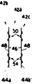
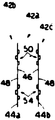
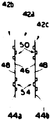
제3도는 제2도 그리드의 하부 오른쪽 코너의 확대된 부분 상부 평면도.3 is an enlarged partial top plan view of the lower right corner of the FIG. 2 grid.
제4도, 제5도, 제6도 및 제7도는 그리드의 주어진 셀의 벽 내에 각 세트의 다수 딤플과 딤플 세트의 배열을 예시하는 제3도의 선 4-4, 5-5, 6-6 및 7-7을 취한 단면도.4, 5, 6, and 7 are lines 4-4, 5-5, 6-6 of FIG. 3, illustrating the arrangement of multiple sets of dimples and dimples within each wall of a given cell of the grid. And cross-section taken 7-7.
제8도는 지지 그리드 내에 딤플세트 배열에 의해서 제공된 구속을 나타내는 개선된 지지 그리드의 두개 인접한 셀 내의 두개 연료봉의 개요도.8 is a schematic diagram of two fuel rods in two adjacent cells of an improved support grid showing the constraints provided by the dimple set arrangement in the support grid.
제9a도에서 제9e도는 개선된 지지 그리드내에서 셀의 대항 벽 두 개 위에 딤플 세트내에 다른 가능한 딤플 배열의 개요도.9a to 9e are schematic views of another possible dimple arrangement in a set of dimples on two opposite walls of the cell in an improved support grid.
* 도면의 주요부분에 대한 부호의 설명* Explanation of symbols for main parts of the drawings
10 : 연료 집합체 12 : 하부노즐10
22 : 상부노즐 16 : 그리드22: upper nozzle 16: grid
18 : 연료봉 32 : 제어봉18: fuel rod 32: control rod
40 : 스트랩 42 : 셀40: strap 42: cell
43 : 용접 비이드 44 : 벽43: welding beads 44: wall
50, 54 : 딤플세트 58, 60, 62 : 딤플50, 54: Dimple set 58, 60, 62: Dimple
본 발명은 일반적으로 원자로에 대한 연료집합체에 관한 것이고 특히, 핵연료봉을 지지하기 위한 개선된 배열의 다수 딤플을 가지는 그리드에 관한 것이다.The present invention relates generally to fuel assemblies for nuclear reactors and, more particularly, to grids having an improved arrangement of multiple dimples for supporting nuclear fuel rods.
대개 원자로에서, 원자로 노심은 다수의 연장된 연료집합체로 구성된다. 이 연료집합체의 통상적 디자인은 연료집합체 길이에 따라 축방향으로 일정한 간격을 가지고 연료집합체의 다수의 연장된 제어봉 안내딤블에 부착된 다수의 그리드에 의해서 조직화된 배열로 유지된 다수의 연료봉을 포함한다. 연료집합체의 대항단부위에 상부 및 하부 노즐은 연료봉의 단부 위와 아래에 다소 뻗은 안내 딤블에 고정된다.Usually in a reactor, the reactor core consists of a number of extended fuel assemblies. A typical design of this fuel assembly includes a plurality of fuel rods held in an organized arrangement by a plurality of grids attached to the plurality of extended control rod guide dimples of the fuel assembly at regular intervals axially along the fuel assembly length. At opposite ends of the fuel assembly the upper and lower nozzles are secured to guide tumbles that extend somewhat above and below the ends of the fuel rods.
이 기술에서 잘 알려진 것처럼 그리드는 원자로심내에 연료봉 사이의 공간을 정확하게 유지하고, 연료봉 진동을 막고, 연료봉에 대한 축방향 지지를 제공하고, 어느 정도까지 종방향 운동에 대하여 봉을 마찰력으로 유지하도록 사용된다.As is well known in the art, the grid is used to accurately maintain the space between the fuel rods within the reactor core, to prevent fuel rod vibration, to provide axial support for the fuel rods, and to maintain the rods to friction to longitudinal motion to some extent. do.
그리드의 통상적 디자인은 연료봉과 제어봉 안내딤블을 개별적으로 수용하는 셀을 형성하도록 설계된 달걀-상자 형상을 가지는 다수의 삽입된 스트랩을 포함한다. 그리드를 따라 주어진 축방향 위치에서 연료봉을 지지하고 수용하는 각 그리드의 셀은 통상적으로 비교적 탄성 스프링 및/또는 삽입된 스트랩의 금속내에 형성된 비교적 다단한 돌출(딤플)을 통상적으로 사용한다. 각 그리드 셀의 스프링과 딤플은 셀을 통해 뻗는 각 연료봉을 마찰력으로 맞물리거나 또는 접촉한다. 또한 일제히 주변에 부착된 외부 스트랩은 그리드에 대해 강도를 제공하는 그리드 스트랩을 둘러싼다.Typical designs of the grid include a plurality of inserted straps having an egg-box shape designed to form cells that individually house fuel rods and control rod guides. The cells of each grid that support and receive fuel rods at a given axial position along the grid typically use relatively high protrusions (dimples) formed in the metal of the relatively elastic springs and / or inserted straps. The springs and dimples of each grid cell engage or frictionally engage each fuel rod extending through the cell. In addition, the outer straps attached all around together surround the grid straps providing strength to the grid.
종래 기술의 대표적인 것은 미합중국 특허 제28,079; 3,679,547; 4,090,918 4,111,348; 4,124,444; 4,25,435; 4,137,125; 4,325,786; 4,364,902; 4,411,862; 4,474,730 호에 예시되고 서술된 그리드이다.Representative of the prior art is US Pat. No. 28,079; 3,679,547; 4,090,918 4,111,348; 4,124,444; 4,25,435; 4,137,125; 4,325,786; 4,364,902; 4,411,862; The grid illustrated and described in 4,474,730.
지르칼로이 종류 물질로 제조된 그리드에 있어서, 그리드 스프링은 원자로 노심내에 연료집합체의 설치후에 방사선 조사 및 온도 효과로 인하여 스프링의 디자인 예비하중을 유지할 수 없다. 어떤 경우에 있어서, 연료봉의 구부림을 제어하기 위해서 필요로 하는 스프링 비율 및 스프링 힘을 얻는 것을 어렵다.In grids made of zircaloy type materials, the grid springs cannot maintain the design preload of the springs due to radiation and temperature effects after the fuel assembly is installed in the reactor core. In some cases, it is difficult to obtain the spring ratio and spring force required to control the bending of the fuel rod.
본 발명의 주요 목적은 원자로 노심내에 연료봉을 지지하기 위해서 필요한 힘과 동시에 소요시간 동안에 최소의 품위 저하를 제공하게 될 연료집합체 그리드내에 개선된 딤플 배열을 제공하는 것이다.It is a primary object of the present invention to provide an improved dimple arrangement in a fuel assembly grid that will provide the minimum deterioration over time as well as the force required to support the fuel rods in the reactor core.
따라서 본 발명은 공동셀의 매트릭스를 형성하기 위해서 배열된 다수의 삽입된 스트랩으로 구성된 핵 연료봉 지지 그리드에 있으며, 핵 연료봉을 수용하기 위한 각 셀은 인접한 셀과 공유되는 대항하게 배치된 연장 벽의 쌍에 의해서 한정되고, 각 한 셀의 각 상기 벽은 상기 한 셀의 주변 일부를 벽의 한 측에 형성하고 벽의 대항측에 상기 한 셀에 인접하게 배치된 몇 개 셀 중에 하나의 주변 부분을 형성하며, (a) 제1세트 딤플은 각 셀을 한정하는 상기 쌍 각 벽의 상단부에 인접하게 형성되고, (b) 제2세트 딤플은 각 셀을 한정하는 상기 쌍 각벽의 하단부에 인접하게 형성되고, 각 상기 제1과 제2세트 딤플은 각각의 세트 딤플이 형성되는 벽의 동일한 한측으로부터 외부에 돌출되는 한쌍의 상부 및 하부 딤플과, 상기 딤플이 형성되는 벽의 대항측으로부터 돌출되고 상기 상부 및 하부 딤플 사이에 위치되는 중심 딤플로 구성되고, 상기 제1과 제2세트 딤플은 인접한 상기 셀을 통해 수용될 때 연료봉을 탄력 및 마찰력으로 맞물리기에 적당한 것을 특징으로 한다.The present invention thus resides in a nuclear fuel rod support grid consisting of a plurality of inserted straps arranged to form a matrix of cavity cells, each cell for receiving nuclear fuel rods pairs of opposingly arranged extension walls shared with adjacent cells. And each said wall of each one cell forms a peripheral portion of said one cell on one side of the wall and forms a peripheral portion of one of several cells disposed adjacent said cell on opposite sides of the wall. (A) the first set of dimples is formed adjacent to an upper end of the bilateral wall defining each cell, and (b) the second set of dimples is formed adjacent to a lower end of the bilateral wall defining each cell; Each of the first and second set dimples may include a pair of upper and lower dimples projecting outward from the same side of the wall on which each set dimple is formed, and from opposite sides of the wall on which the dimples are formed. And a central dimple projecting and positioned between the upper and lower dimples, wherein the first and second set dimples are adapted to engage the fuel rods with elastic and frictional forces when received through the adjacent cells.
위에서 한정한 것처럼 본 발명에 따른 딤플세트 배열은 그리드 셀 벽내에서 모멘트를 최소화할 것이다. 본 발명을 실시하는 여러가지 특정한 배열은 연료봉이 측 변위와 회전에 대해서 제한하는 반경식 셀을 형성하기 위해서 가능할 수 있다. 양호하게, 개선된 그리드의 스트랩은 용접 비이드의 형성에 의해서 스트랩의 각 교차점에서 결합된다.As defined above, the dimple set arrangement according to the invention will minimize the moment within the grid cell walls. Various specific arrangements for practicing the present invention may be possible to form a radial cell in which the fuel rod is limited to side displacement and rotation. Preferably, the straps of the improved grid are joined at each intersection of the straps by the formation of weld beads.
다음 서술에 있어서 동일한 참조 기호는 몇 개의 도면을 통해 동일하거나 또는 대응하는 부품;타내고, "앞", "뒤", "왼쪽", "오른쪽", "위쪽", "아래쪽" 등과 같은 용어는 제한된 용어로서 해석되지 않고 편리하게 사용된다.In the following description, the same reference signs refer to the same or corresponding parts throughout the several views; such terms as "front", "back", "left", "right", "top", "bottom", etc. It is not construed as a limited term and is used conveniently.
도면에 있어서, 특히 제1도에서, 종방향으로 단축된 형태로 표시되고 기호(10)으로 일반적으로 나타내는 연료집합체의 정단면도가 예시된다. 연료집합체(10)는 기본적으로 원자로(도시되지 않음)의 노심 영역내에 하부 노심판(도시되지 않음)에 대하여 집합체를 지지하기 위한 하부노즐(또는 하단부 구조물)(12)과, 하부노즐(12)로부터 위쪽으로 돌출되는 다수의 종방향으로 뻗은 안내딤블(또는 안내관)(14)을 포함한다. 집합체(10)는, 또한, 지금부터 상세히 서술된 본 발명의 개선된 구조를 가지는 다수의 횡방향 그리드(16)를 포함한다.In the drawings, in particular in FIG. 1, a cross-sectional front view of the fuel assembly, shown in a longitudinally shortened form and generally represented by the
그리드(16)는 안내딤블(14)과 그리드(16)에 의해서 횡방향으로 일정한 간격으로 유지되는 연장된 연료봉(18)의 조직화된 배열을 따라서 축방향으로 일정한 간격을 가진다. 역시, 집합체(10)는 집합체의 중심내에 위치된 계기관(20)과 안내딤블(14)의 상단부에 부착된 상부노즐(또는 상단부 구조물)(22)을 가진다. 위와 같이 부품이 배치되는 연료집합체(10)는 집합체 부품 손상없이 통상적으로 조종되는 것이 가능할 수 있는 완전한 장치를 형성한다.The
위에서 언급한 것처럼, 연료집합체 길이를 따라 일정한 간격을 가지는 집합체(10)내에 배열된 연료봉(18)은 본 발명의 그리드(16)에 의해서 서로 관련되어 유지된다.As mentioned above, the
각 연료봉(18)은 핵 연료 펠릿(24)과 봉을 밀봉하기 위해서 상부 및 하단부 플러그(26, 28)에 의해서 폐쇄된 봉의 대향단부를 포함한다. 통상적으로, 플리넘 스프링(30)은 봉(18)내에 팽팽하고 스택되게 펠릿을 유지하기 위해서 상단부 플러그(26)와 펠릿(24) 사이에 배치된다.Each
핵 분열 물질로 구성되는 연료 펠릿(24)은 원자로의 반응력을 발생시킬 수 있다. 물, 또는 붕소를 섞은 물과 같은 액체 감속재/냉각재는 유용한 작업을 제공하기 위하여 노심내에서 발생되는 열을 추출하도록 노심의 연료집합체를 통하여 위쪽으로 펌프된다.
분열 과정을 제어하기 위해서 다수의 제어봉(32)은 연료집합체(10)의 기정된 위치에서 위치된 안내딤블(14)내에서 서로 이동할 수 있다. 특히, 상부노즐(22)은 내부의 나선형 원통부재(36)를 가지는 봉 클러스터 제어 메커니즘(34)과 다수의 방사상으로 뻗은 플루우크 아암(38)을 포함한다. 각 아암(38)은 제어 메커니즘(34)이 안내딤블(14)내에 제어봉(32)을 수직적으로 움직일 수 있고 그것에 의해서 연료집합체(10)의 핵 분열 과정을 제어하도록 제어봉(32)에 상호 연결된다.In order to control the splitting process, the plurality of
[개선된 연료봉 지지 그리드 구조][Enhanced Fuel Rod Support Grid Structure]
원자로심내에 연료봉(18) 사이에 공간을 정확하게 유지하고 연료봉의 측방향과 종방향 운동을 저지하고 봉의 유효한 실제수명 동안에 구부러질 가능성을 최소화하기 위해서, 개개의 연료봉 원주에 대해 힘을 가하도록 본 발명에 따라 설계된 그리드(16)는 봉의 종방향 축에 대하여 내부에 방사상으로 돌출된다.The present invention is designed to exert a force on the individual fuel rod circumferences to precisely maintain the space between the
제2도에서 7도를 참조하면, 각 그리드(16)는 42로표시된 공동셀 매트릭스를 형성하도록 만들어진 달걀상자 형상을 가지는 다수의 삽입된 내부 스트랩(40), 하나의 연료봉(18)을 개별적으로 수용하는 다수의 공동셀과 하나의 제어봉 안내딤블(14)을 수용하는 소수의 공동셀을 포함한다. 내부 그리드 스트랩(40)의 각 교차점에서, 스트랩은 용접 비이드(43)의 형성에 의해서 결합된다. 하나의 연료봉(18)을 수용하기 위한 각 셀(42)은 인접한 셀과 공유되는 두쌍의 대항하는 연장된 벽(44)에 의해서 한정된다.Referring to FIGS. 2 to 7, each
한 셀(42)을 한정하는 두쌍의 대항하는 연장된 벽(44) 중에서 각 벽(44)은 한 셀(42)의 주변 일부를 형성하는 한측(46)을 가지고 한 셀에 인접하게 배치된 몇개 셀(42)중에서 한 셀 주변 일부를 형성하는 대항측(48)을 역시 가진다.Of the two pairs of opposing
제3도에서 7도 내에 상세히 예시된 것처럼, 각 지지 그리드(16)에 의해서 연결된 본 발명은 그리드(16)의 각 셀(42)을 한정하는 두쌍의 대항하는 연장된 벽 중에서 각 벽(44)의 상단부(52)에서 형성되고 일반적으로 50으로 표시되는 제1세트의 딤플을 포함한다. 각 지지 그리드(16)는 각 그리드 셀(42)을 한정하는 두 쌍의 대항하는 연장된 벽(44) 중에서 하단부(56)에서 형성되고, 일반적으로 54로 표시되는 제2세트의 딤플을 포함한다.As illustrated in detail in FIG. 3 to FIG. 7, the present invention connected by each
특히, 제1및 제2세트 딤플(50,54) 각각의 셀 벽(44)의 동일한 하나 측(46)으로부터 외부에 돌출된 한쌍의 상부 및 ; 딤플(58,60)과 상부 및 하부 딤플(58,60)에 인접하고 사이에 위치되고 벽(44)의 대항측(48)으로부터 반대 방향으로 외부에 돌출된 중심 딤플(62)로 구성된다.In particular, a pair of tops projecting outward from the same one
각 셀(42)을 한정하는 두쌍의 대항하는 연장된 벽(44) 중에서 벽(44) 위에 제1세트 딤플(50)은 일반적으로 동일평면에서 형성된다. 유사하게, 각 그리드 셀(42)을 한정하는 벽(44)위에 제2세트 딤플(54)은 일반적으로 동일 평면에서 형성된다.Of the two pairs of opposing elongated
디플의 제1및 제2세트(50,54)내에서 딤플(58,60,62)은 각 셀(42)을 통해 수용될 때 연료봉(18)을 탄력 및 마찰력으로 맞물리기에 적당하다.
특히, 딤플(58,60,62)은 통상적으로 다이 펀칭과 변형 기술에 의한 적당한 방법으로 내부 스트랩(40)의 지르칼로이와 같은 금속 물질로부터 제조된다. 딤플은 U자 형상을 가진다.In particular, the
왜냐하면, 딤플은 엇갈림 방식으로 셀 벽(44)으로부터 외부에 돌출되고, 또한 딤플은 높은 스프링 비율에 도달할 수 있고 비록 딤플이 형성되는 곳으로부터 스트랩(40)이 비교적 유연성을 가질지라도 연료봉에 대하여 제어력을 제공할 수 있는 비교적 강한 돌출을 제공하기 때문이다. 또한 강도는 일제히 주변에 부착된 일련의 외부 스트랩(64)이 내부 스트랩(40)을 둘러싸고 연결되는 것에 의해서 그리드(91)에 대해 제공된다.Because the dimples project outwardly from the
제8도는 지지 그리드(16)내에서 두개 인접한 셀(42)을 통해 배치되는 두개 연료봉(18)을 나타내었다. 셀(42)을 한정하는 벽(44)위에 딤플세트(50,54)의 배열이 그리드(16)의 상부에서 두개 연료봉 서로에 대하여 구부러짐을 저지하게 작용하는 힘을 제공하는 방법을 나타낸다.8 shows two
첫째, 개개의 연료봉(18)의; 은 제지 모멘트를 제공하는 각 딤플세트에서 그리드 딤플 힘에 의해 제지된다.First, of
둘째, 제8도의 연료봉(18) 사이의 벽(44) 위에 딤플세트(50)와 같이 직접적 압축하에 특정한 딤플세트는 셀벽을 통과하는 하중 통로에 대한 밀접한 근접 때문에 매우 단단하다. 이 단단함은 다른 연료봉에 대하여 연료봉(18)의 측 운동을 제한한다.Second, certain dimple sets under direct compression, such as a set of
결국, 단지 3분의 1의 작은 억제모멘트 기여는 연료봉(18)에 작용하는대항하는 벽위에 딤플의 대항세트의 상호작용에 의해서 각 딤플 세트 입면에서 제공된다.As a result, only one third of the suppression moment contribution is provided at each dimple set elevation by the interaction of an opposite set of dimples on an opposing wall acting on the
제9a도에서 9e도는 지지 그리드(16) 내에서 한 셀(42a)을 한정하는 4개 대항 벽(44)중에서 두 개 벽(44) 위에 딤플 세트(50,54)내에 5개 다른 배열의 딤플(58,60,62)을 간략하게 예시된다. 4개 대항 벽(44)중에서 다른 두개는 역시 이 배열의 어떤 것을 포함할 수 있다.9a to 9e show five different arrangements of dimples in the set of
제9a도에서, 한셀(42a)을 한정하는 한쌍의 벽(44)중에서 한 벽(44a)위에 제1및 제2세트 딤플(50,54) 각 내에 상부 및 하부 딤플(58,60)과, 다른 벽(44b)위에 제1및 제2세트 딤플(50,54) 각 내에 중심 딤플(62)은 인접한 셀(42)(42b, 42c)내에 각각의 하나 및 다른 벽(44a,44b)의 대항 측(48)으로부터 외부에 돌출된다.In FIG. 9A, the upper and
한편, 한셀(42a)을 한정하는 한쌍의 벽(44)중에서 후자 벽(44b)위에 제1및 제2세트 딤플(50,54) 각 내에 상부 및 하부 딤플(58,60)과, 전자의 벽(44a)위에 제1및 제2세트 딤플(50,54) 각내에 중심 딤플(62)은 한셀(42a)내에 각각의 한벽 및 다른벽(44a,44b)의 한측(46)으로부터 내부에 돌출된다.On the other hand, of the pair of
제9b도에서, 한셀(42a)을 한정하는 한쌍의 벽(44)중에서 양벽(44a,44b)위에 제1및 제2세트(50,54) 딤플 각 내에 상부 및 하부 딤플(58,60)은 인접한 셀(42b,42c)내에 각 벽(44a,44b)의 대항측(48)으로부터 외부에 돌출된다.In FIG. 9B, the upper and
한편, 한셀(42a)을 한정하는 한쌍의 벽(44)중에서 양벽(44a,44b)위에 제1및 제2세트(50,54) 딤플 각내에 중심 딤플(62)은 한셀(42a)내에 각 벽(44a,44b)의 한측(46)으로부터 내부에 돌출된다.On the other hand, in the pair of
제9c도에서, 한셀(42a)을 한정하는 한쌍의 벽(44)중에서 양벽(44a,44b)위에 제1및 제2세트(50,54) 딤플 각 내에 상부 및 하부 딤플(58,60)은 한셀(42a)내에 각 벽(44a,44b)의 한측으로부터 내부에 돌출된다.In FIG. 9C, the upper and
한편, 한셀(42a)을 한정하는 한쌍의 벽(44)중에서 양벽(44a,44b)위에 제1및 제2세트(50,54) 딤플 각내에 중심 딤플(62)은 인접한 셀(42b,42c)내에 각 벽(44)의 대항 측(48)으로부터 외부에 돌출된다.On the other hand, in the pair of
제9d도에서, 한셀(42a)을 한정하는 한쌍의 벽(44)중에서, 한벽(44a)위에 제1세트 딤플(50)내에 상부 및 하부 딤플(58,60)과 제2세트 딤플(54)내에 중심 딤플(62)과, 다른 벽(44b)위에 제1세트 딤플(50)내에 중심 딤플(62)과 제2세트 딤플(54)내에 상부 및 하부 딤플(58,60)은 인접한 셀(42b,42c)내에 각각의 하나 및 다른 벽(44a,44b)의 대항측으로부터 외부에 돌출된다.In FIG. 9D, of the pair of
한편, 한셀(42a)을 한정하는 한쌍의 벽(44)중에서 한벽(44a)위에 제1세트 딤플(50)내에 중심 딤플(62)과, 제2세트 딤플(54)내에 상부 및 하부 딤플(58,60)과, 다른벽(44b) 위에 제1세트 딤플(50)내에 상부 및 하부 딤플(58,60)과 제2세트 딤플(54)내에 중심 딤플(62)은 한셀(42a)내에 각각의 한벽 및 다른 벽(44a,44b)의 한측(46)으로부터 내부에 돌출된다.On the other hand, in the pair of
제9e도에서, 한셀(42a)을 한정하는 한쌍의 벽(44)중에서, 한벽(44a)위에 제1세트 딤플(50)내에 상부 및 하부 딤플(58,60)과 제2세트 딤플(54)내에 중심 딤플(62)과, 다른 벽(44)(44b)위에 제1세트 딤플(50)내에 상부 및 하부 딤플(58,60)과 제2세트 딤플(54)내에 중심 딤플(62)은 인접한 셀(42b,42c)내에 각각의 한벽 다른 벽(44a,44b)의 대항 측(48)으로부터 외부에 돌출된다.In FIG. 9E, of the pair of
한편, 한셀(42a)을 한정하는 한쌍의 벽(44)중에서, 한벽(44a)위에 제1세트 딤플(50)내에 중심 딤플(62)과 제2세트 딤플(54)내에 상부 및 하부 딤플(58,60)과, 다른 벽(44b)위에 제1세트 딤플(50)내에 중심 딤플(62)과 제2세트 딤플(54)내에 상부 및 하부 딤플(58,60)은 한셀(42a)내에 각각의 한벽 및 다른 벽(44a,44b)의 한측(46)으로부터 내부에 돌출된다.On the other hand, of the pair of
Claims (8)
Applications Claiming Priority (2)
| Application Number | Priority Date | Filing Date | Title |
|---|---|---|---|
| US729,387 | 1985-05-01 | ||
| US06/729,387 US4659541A (en) | 1985-05-01 | 1985-05-01 | Nuclear fuel rod support grid with improved multiple dimple arrangement |
Publications (2)
| Publication Number | Publication Date |
|---|---|
| KR860009436A KR860009436A (en) | 1986-12-23 |
| KR940003800B1 true KR940003800B1 (en) | 1994-05-03 |
Family
ID=24930800
Family Applications (1)
| Application Number | Title | Priority Date | Filing Date |
|---|---|---|---|
| KR1019860003190A KR940003800B1 (en) | 1985-05-01 | 1986-04-25 | Nuclear fuel rod support grid |
Country Status (7)
| Country | Link |
|---|---|
| US (1) | US4659541A (en) |
| EP (1) | EP0200046B1 (en) |
| JP (1) | JPS61253493A (en) |
| KR (1) | KR940003800B1 (en) |
| CN (1) | CN86102919A (en) |
| DE (1) | DE3668718D1 (en) |
| ES (1) | ES297131Y (en) |
Families Citing this family (15)
| Publication number | Priority date | Publication date | Assignee | Title |
|---|---|---|---|---|
| US4781884A (en) * | 1987-03-02 | 1988-11-01 | Combustion Engineering, Inc. | Debris catching strainer grid |
| US5444748A (en) * | 1994-04-04 | 1995-08-22 | Westinghouse Electric Corporation | Grid structure for supporting fuel rods in a nuclear reactor |
| US5488644A (en) * | 1994-07-13 | 1996-01-30 | General Electric Company | Spring assemblies for adjoining nuclear fuel rod containing ferrules and a spacer formed of the spring assemblies and ferrules |
| US5519747A (en) * | 1994-10-04 | 1996-05-21 | General Electric Company | Apparatus and methods for fabricating spacers for a nuclear fuel rod bundle |
| US5546437A (en) * | 1995-01-11 | 1996-08-13 | General Electric Company | Spacer for nuclear fuel rods |
| US5566217A (en) * | 1995-01-30 | 1996-10-15 | General Electric Company | Reduced height spacer for nuclear fuel rods |
| US5675621A (en) * | 1995-08-17 | 1997-10-07 | General Electric Company | Reduced height flat spring spacer for nuclear fuel rods |
| US6606369B1 (en) | 2002-03-06 | 2003-08-12 | Westinghouse Electric Company Llc | Nuclear reactor with improved grid |
| US6819733B2 (en) | 2002-05-15 | 2004-11-16 | Westinghouse Electric Company Llc | Fuel assembly and associated grid for nuclear reactor |
| US7028765B2 (en) * | 2003-11-25 | 2006-04-18 | Trico Non-Ferrous Metal Products, Inc. | Heat exchanger tube support |
| DE10358830B3 (en) * | 2003-12-16 | 2005-08-18 | Framatome Anp Gmbh | Fuel element for a pressurized water nuclear reactor and constructed with such fuel core of a pressurized water reactor |
| US7889829B2 (en) * | 2004-09-02 | 2011-02-15 | Westinghouse Electric Company Llc | Nuclear fuel assembly protective grid |
| KR101163998B1 (en) | 2010-09-15 | 2012-07-18 | 한국수력원자력 주식회사 | Dual-cooled fuel rod's spacer grids with upper and lower cross-wavy-shape dimple |
| CN106531231B (en) * | 2016-11-30 | 2018-05-22 | 中广核研究院有限公司 | Fuel assembly and its clamping device |
| CN113222288B (en) * | 2021-06-02 | 2022-05-17 | 山东建筑大学 | Classified evolution and prediction method of village and town community space development map |
Family Cites Families (21)
| Publication number | Priority date | Publication date | Assignee | Title |
|---|---|---|---|---|
| US28079A (en) * | 1860-05-01 | Hominy-mill | ||
| US25393A (en) * | 1859-09-13 | David decker | ||
| FR1480965A (en) * | 1965-05-25 | 1967-08-09 | ||
| US3679547A (en) * | 1968-12-16 | 1972-07-25 | Atomic Power Dev Ass Inc | Elastic support grid for nuclear fuel elements |
| DE2027968A1 (en) * | 1970-06-06 | 1971-12-16 | Babcock & Wilcox Ag | Tube bundle space grillage - allowing lateral deflection of spacer - strips during tube insertion |
| US4124444A (en) * | 1971-01-11 | 1978-11-07 | The Babcock & Wilcox Company | Nuclear fuel rod supporting arrangement |
| US3932216A (en) * | 1971-12-13 | 1976-01-13 | The Babcock & Wilcox Company | Industrial technique |
| US3920515A (en) * | 1972-09-26 | 1975-11-18 | Westinghouse Electric Corp | Fuel assembly for a nuclear reactor |
| US3933584A (en) * | 1973-04-23 | 1976-01-20 | Nuclear Fuel Services, Inc. | Grid for nuclear fuel assembly |
| US4165256A (en) * | 1975-03-03 | 1979-08-21 | The Babcock & Wilcox Company | Fuel element grid plate with corrugation and bosses |
| JPS5236283A (en) * | 1975-03-12 | 1977-03-19 | Genshi Nenryo Kogyo | Nuclear fuel assembly supporting spacer structure |
| US4137125A (en) * | 1976-11-12 | 1979-01-30 | Westinghouse Electric Corp. | Method of welding nuclear reactor fuel assemblies |
| US4125435A (en) * | 1977-02-25 | 1978-11-14 | The Babcock & Wilcox Company | Grid lattice with sliding strap |
| US4111348A (en) * | 1977-03-09 | 1978-09-05 | Westinghouse Electric Corp. | Grid braze application mold |
| FR2397042A1 (en) * | 1977-07-07 | 1979-02-02 | Commissariat Energie Atomique | SPACING GRID FOR A BUNDLE OF COMBUSTIBLE PENCILS IN A NUCLEAR REACTOR ASSEMBLY |
| FR2465296A1 (en) * | 1979-09-06 | 1981-03-20 | Commissariat Energie Atomique | DEVICE FOR FIXING A SPRING ON A SPACING GRID OF COMBUSTIBLE ELEMENTS OF NUCLEAR REACTORS |
| US4325786A (en) * | 1979-11-29 | 1982-04-20 | Combustion Engineering, Inc. | Spacer grid for reducing bowing in a nuclear fuel assembly |
| FR2474229B1 (en) * | 1980-01-22 | 1986-08-22 | Commissariat Energie Atomique | SPACER GRILLE FOR FUEL ASSEMBLY OF NUCLEAR REACTOR |
| GB2109665B (en) * | 1981-11-18 | 1985-07-24 | Standard Telephones Cables Ltd | Composite animal feed additives |
| KR860000966B1 (en) * | 1981-11-30 | 1986-07-23 | 엘돈 에이취. 루터 | Anti-bow grid for nuclear fuel assembly |
| US4474730A (en) * | 1982-08-05 | 1984-10-02 | Westinghouse Electric Corp. | Nuclear fuel spacer grid |
-
1985
- 1985-05-01 US US06/729,387 patent/US4659541A/en not_active Expired - Fee Related
-
1986
- 1986-04-10 EP EP86104922A patent/EP0200046B1/en not_active Expired - Lifetime
- 1986-04-10 DE DE8686104922T patent/DE3668718D1/en not_active Expired - Fee Related
- 1986-04-25 KR KR1019860003190A patent/KR940003800B1/en active IP Right Grant
- 1986-04-29 ES ES1986297131U patent/ES297131Y/en not_active Expired
- 1986-04-30 CN CN198686102919A patent/CN86102919A/en active Pending
- 1986-04-30 JP JP61098433A patent/JPS61253493A/en active Granted
Also Published As
| Publication number | Publication date |
|---|---|
| ES297131U (en) | 1989-03-16 |
| DE3668718D1 (en) | 1990-03-08 |
| US4659541A (en) | 1987-04-21 |
| KR860009436A (en) | 1986-12-23 |
| EP0200046B1 (en) | 1990-01-31 |
| CN86102919A (en) | 1986-11-05 |
| JPS61253493A (en) | 1986-11-11 |
| JPH0457238B2 (en) | 1992-09-10 |
| ES297131Y (en) | 1989-10-01 |
| EP0200046A1 (en) | 1986-11-05 |
Similar Documents
| Publication | Publication Date | Title |
|---|---|---|
| US4895698A (en) | Nuclear fuel rod grip with modified diagonal spring structures | |
| KR940003800B1 (en) | Nuclear fuel rod support grid | |
| US4957697A (en) | Nuclear fuel rod support grid with generally S-shaped spring structures | |
| US4885127A (en) | Nuclear fuel rod support grid with attachable spring and dimple support spacers | |
| US4923669A (en) | Nuclear fuel rod grid spring and dimple structures having chamfered edges for reduced pressure drop | |
| US4508679A (en) | Nuclear fuel assembly spacer | |
| US4061536A (en) | Fuel assembly for nuclear reactors | |
| US4585616A (en) | Nuclear fuel spacer grid with improved outer straps | |
| US5434898A (en) | Nuclear fuel assembly | |
| KR0121455B1 (en) | Nuclear fuel rod grid spring and dimple structures | |
| US4544522A (en) | Nuclear fuel assembly spacer | |
| US4474730A (en) | Nuclear fuel spacer grid | |
| US4056441A (en) | Bracing device for a bundle of parallel pins in a nuclear reactor assembly | |
| US4714585A (en) | Interlocking egg-crate type grid assembly | |
| US4357298A (en) | Nuclear fuel assembly space arrangement | |
| US4125435A (en) | Grid lattice with sliding strap | |
| US4585615A (en) | Nuclear fuel spacer grid with improved grid straps | |
| US3719560A (en) | Fuel assembly for a nuclear reactor using zirconium alloy clad fuel rods | |
| US3137638A (en) | Neutronic reactor fuel elements | |
| US5247551A (en) | Spacer sleeve for nuclear fuel assembly | |
| US4314884A (en) | Nuclear fuel assembly | |
| US4587704A (en) | Method of mounting a continuous loop spring on a nuclear fuel spacer | |
| JPH0573194B2 (en) | ||
| US4571324A (en) | Nuclear fuel assembly spacer | |
| US3890196A (en) | Nuclear reactor fuel element assembly spacer grid and method of making |
Legal Events
| Date | Code | Title | Description |
|---|---|---|---|
| A201 | Request for examination | ||
| G160 | Decision to publish patent application | ||
| E701 | Decision to grant or registration of patent right | ||
| NORF | Unpaid initial registration fee |