KR930010470B1 - Method and apparatus for measuring the level of a fluent material in a container - Google Patents
Method and apparatus for measuring the level of a fluent material in a container Download PDFInfo
- Publication number
- KR930010470B1 KR930010470B1 KR1019850002790A KR850002790A KR930010470B1 KR 930010470 B1 KR930010470 B1 KR 930010470B1 KR 1019850002790 A KR1019850002790 A KR 1019850002790A KR 850002790 A KR850002790 A KR 850002790A KR 930010470 B1 KR930010470 B1 KR 930010470B1
- Authority
- KR
- South Korea
- Prior art keywords
- waveguide
- signal
- mode
- level
- reflector
- Prior art date
Links
Images


Classifications
-
- B—PERFORMING OPERATIONS; TRANSPORTING
- B04—CENTRIFUGAL APPARATUS OR MACHINES FOR CARRYING-OUT PHYSICAL OR CHEMICAL PROCESSES
- B04B—CENTRIFUGES
- B04B3/00—Centrifuges with rotary bowls in which solid particles or bodies become separated by centrifugal force and simultaneous sifting or filtering
-
- G—PHYSICS
- G01—MEASURING; TESTING
- G01F—MEASURING VOLUME, VOLUME FLOW, MASS FLOW OR LIQUID LEVEL; METERING BY VOLUME
- G01F23/00—Indicating or measuring liquid level or level of fluent solid material, e.g. indicating in terms of volume or indicating by means of an alarm
- G01F23/22—Indicating or measuring liquid level or level of fluent solid material, e.g. indicating in terms of volume or indicating by means of an alarm by measuring physical variables, other than linear dimensions, pressure or weight, dependent on the level to be measured, e.g. by difference of heat transfer of steam or water
- G01F23/28—Indicating or measuring liquid level or level of fluent solid material, e.g. indicating in terms of volume or indicating by means of an alarm by measuring physical variables, other than linear dimensions, pressure or weight, dependent on the level to be measured, e.g. by difference of heat transfer of steam or water by measuring the variations of parameters of electromagnetic or acoustic waves applied directly to the liquid or fluent solid material
- G01F23/284—Electromagnetic waves
-
- G—PHYSICS
- G01—MEASURING; TESTING
- G01S—RADIO DIRECTION-FINDING; RADIO NAVIGATION; DETERMINING DISTANCE OR VELOCITY BY USE OF RADIO WAVES; LOCATING OR PRESENCE-DETECTING BY USE OF THE REFLECTION OR RERADIATION OF RADIO WAVES; ANALOGOUS ARRANGEMENTS USING OTHER WAVES
- G01S13/00—Systems using the reflection or reradiation of radio waves, e.g. radar systems; Analogous systems using reflection or reradiation of waves whose nature or wavelength is irrelevant or unspecified
- G01S13/02—Systems using reflection of radio waves, e.g. primary radar systems; Analogous systems
- G01S13/06—Systems determining position data of a target
- G01S13/08—Systems for measuring distance only
Landscapes
- Physics & Mathematics (AREA)
- Electromagnetism (AREA)
- Radar, Positioning & Navigation (AREA)
- Remote Sensing (AREA)
- General Physics & Mathematics (AREA)
- Engineering & Computer Science (AREA)
- Fluid Mechanics (AREA)
- Thermal Sciences (AREA)
- Computer Networks & Wireless Communication (AREA)
- Measurement Of Levels Of Liquids Or Fluent Solid Materials (AREA)
- Level Indicators Using A Float (AREA)
- Measurement Of Radiation (AREA)
- Length-Measuring Devices Using Wave Or Particle Radiation (AREA)
Abstract
내용 없음.No content.
Description
제1도는 본 발명의 주요응용법을 제공하는 하나의 오일 탱크의 수직 단면도.1 is a vertical cross-sectional view of one oil tank providing the main application of the present invention.
제2도는 본 발명에 따른 모우드발진기(mode generator)와 제1도의 탱크속으로 연장된 도파관(waveguide)으로 사용된 파이프의 상부전체의 수직단면을 도시한 단면도.FIG. 2 is a cross-sectional view showing a vertical section of the entire upper part of a pipe used as a mode generator and a waveguide extending into the tank of FIG. 1 according to the present invention. FIG.
제3도는 제2도의 장치의 부품을 포함하는 모우드필터(mode filter)의 평면도.3 is a plan view of a mode filter comprising components of the apparatus of FIG.
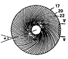
제4도는 제2도 장치의 부품을 포함하는 반사경(reflecton)의 저면도.4 is a bottom view of a reflector that includes components of the FIG. 2 device.
제5도는 제4도의 Ⅴ-Ⅴ선 단면도.5 is a cross-sectional view taken along the line VV of FIG.
* 도면의 주요부분에 대한 부호의 설명* Explanation of symbols for main parts of the drawings
1 : 탱크 5 : 발판1: tank 5: scaffolding
7 : 파이프(도파돤) 9 : 구멍7: pipe (dopa) 9: hole
10 : 액표면 11 : 발진기10 liquid surface 11: oscillator
12 : 도파관 13 : 동축도관(케이블)12
14 : 하우징 15 : 방사관14
16 : 반사경 18 : 도체16: reflector 18: conductor
22 : 리이드22: lead
본 발명의 송신기로부터 관상 도파관을 통하여 공급되는 초단파 신호를 사용하여 용기 내에 저장된 유체의 레벨을 측정하는 방법에 관한 것이다. 여기서, 상기의 관상 도파관은 용기의 하부로 수직 연장되고, 도파관 속의 재료의 표면은 주변 포위재료의 레벨을 따르도록 유체와 연결된다. 그리고 상기의 신호는 진도파관의 표면에서 반사되고, 수신기로 유도되어 전자적 유니트에서 신호처리 후 용기 내 재료의 레벨을 결정하기 위하여 사용된다.A method of measuring the level of fluid stored in a vessel using microwave signals supplied through a tubular waveguide from a transmitter of the present invention. Here, the tubular waveguide extends vertically to the bottom of the vessel, and the surface of the material in the waveguide is connected with the fluid so as to follow the level of the surrounding envelope material. The signal is then reflected off the surface of the waveguide and guided to the receiver and used to determine the level of material in the vessel after signal processing in the electronic unit.
또한 본 발명의 상기 방법을 실시하는 장치에도 관계된다. 미합중국 특허 제4,044,355호에서 기술된 바와 같이 탱크(tank) 혹은 시스테른(citstern)과 유사한 용기에 채워진 액체 또는 유사-액체(liquid-lke) 재료의 레빌을 측정하는데 레이다가 사용될 수 있다. 공기 또는 기타 가스 속에서의 레이다 전파의 속도는 극히 안정되어 있기 때문에 매우 정확한 값이 없어지고 레이터 안테나는 극히 영구적인 재료로 제작될 수 있어서 온도, 화학적 부식 및 기계적 용력 등이 극히 극한 상황인 환경에도 이러한 레벨측정기가 사용될 수 있다. 또한 레이다 안테나는 탱크의 상부 구멍을 통하여 장착될 수 있기 때문에 이것의 설치는 간단하고 보수 및 즉시 고체를 실시하기 쉽게 된다.It also relates to an apparatus for implementing the above method of the present invention. Radars may be used to measure the level of a liquid or liquid-lke material filled in a tank or container similar to citstern as described in US Pat. No. 4,044,355. Because the speed of radar propagation in air or other gases is extremely stable, very accurate values are lost and the radar antenna can be made of extremely permanent materials, even in environments with extreme temperatures, chemical corrosion and mechanical forces. Such a level meter can be used. In addition, since the radar antenna can be mounted through the top hole of the tank, its installation is simple, easy to repair and to perform solid immediately.
종래에는 탱크 속의 지주(struts), 사다리, 파이프 등의 위치 사이에 일정한 공간이 있어야만 레이다 빔을 설치할 수 있다는 것이 레이다 레벨측정을 제한하는 주용 요인이었다. 만약 직경이 D인 원형 레이다 안테나가 사용된다면, 사용할 수 있는 레이다 빔의 폭은 약 λ/D 레디안이지만, 레이다 빔의 영역확산을 고려하면 약 2λ/D 레디안의 꼭지각을 갖는 원추공간이 있어야 한다. 여기서, λ는 레이다 반송파의 파장을 표시한다. 예로서 3cm일 수 있다. 여러 실제적 문제를 고려하여 안테나 직경은 일정한 범위 내로 잡혀져야 한다. 그리고 반송파의 파장은 극히 높은 반송파 주파수에서 레이다 송신기와 다른 요소들이 고가로 되고 제한적임을 감안하여 실제에서 하향 조정되어야 한다. 그래서 레이다 빔이 독단적으로 좁을 수 없고 적어도 많은 응융에서 이것이 바람직스럽지 못하다. 예를 들면 가변 트림과 리스트(varying trim and list)를 가지는 탱크에 장치가 사용되었을 때와 같은 경우이다. 실제의 경우, 5-15°의 각기 대표적 공간으로 채택될 수 있다. 이것은 많은 탱크들이 자유공간진파를 가진 레이타 레벨측정기 설치를 허용하지 않는다는 것을 뜻한다. 이것은 소위 부유지붐을 가진 탱크(tank with floating roofs), 즉 지붕이 내용물의 위에 직접 부유하는 탱크 또는 시스테른(cisterns)에서도 마찬가지다.Conventionally, the main factor limiting the radar level measurement is that the radar beam can be installed only when there is a certain space between the positions of struts, ladders, pipes, etc. in the tank. If a circular radar antenna of diameter D is used, the width of the available radar beam is about λ / D radians, but considering the area spread of the radar beam, there should be a cone space with a vertex angle of about 2λ / D radians. Is the wavelength of the radar carrier. For example, it may be 3 cm. Taking into account a number of practical problems, the antenna diameter must be taken within a certain range. And the wavelength of the carrier should be adjusted downward in practice considering that radar transmitters and other elements are expensive and limited at extremely high carrier frequencies. So the radar beam cannot be arbitrarily narrow and at least in many agglomerations this is undesirable. This is the case, for example, when the device is used in a tank with a variable trim and list. In practice, they can be adopted as representative spaces of 5-15 ° respectively. This means that many tanks do not allow the installation of a radar level meter with free space vibrations. The same is true for so-called tanks with floating roofs, ie tanks or cisterns in which the roof floats directly on the contents.
상기 언급한 제한을 피하기 위한 방법은 탱크 하부로 연장된 도파관으로 레이다 전파를 안내하는 것이다. 이런 방법을 다른 레벨측정이 시도된 적이 있지만(미합중국 특허 제4,359,908호 참조) 채용될 레이다 주파수 범위에 적당하기 위하여 표준 도파관은 비교적 작은 직경을 갖는다는 사실 때문에 실시에 있어서 많은 제약이 따랐다. 언급된 도파관에는 원-모드(one-mode) 전달만 허용하는 형상의 금속제 각형 또는 원통 파이프들이 있다. 원형 도파관에 있어 이것은 파장 λ가 파이프의 내경에 1.3-1.7배 사이에 있어야 함을 뜻하고, 그래서 상용적인 레이다 주파수에 대하여 파이프 내경이 단지 2-3cm 정도임을 뜻한다.A way to avoid the aforementioned limitation is to guide radar propagation into a waveguide extending under the tank. Although other level measurements have been attempted with this method (see US Pat. No. 4,359,908), many limitations have been made in practice due to the fact that standard waveguides have a relatively small diameter to be suitable for the radar frequency range to be employed. The waveguides mentioned are metal square or cylindrical pipes of a shape that allows only one-mode transmission. For circular waveguides, this means that the wavelength λ must be between 1.3 and 1.7 times the inner diameter of the pipe, so that the pipe inner diameter is only 2-3 cm for commercial radar frequencies.
이러한 도파관은 하기의 문제를 나타낸다. 만약 탱크에 왁스가 풍부한 원유를 넣는다면 상기 파이프는 막히게 된다.This waveguide presents the following problem. If you put wax-rich crude oil in the tank, the pipe will clog.
레이다 전파의 전달은 외측과 내측 사이의 액체의 자유 흐름을 보장하는데 필요한 관상 도파관벽의 구멍에 의하여 심각하게 영향을 받는다.The transmission of radar propagation is severely affected by the holes in the tubular waveguide walls required to ensure free flow of liquid between the outside and the inside.
파이프 내의 부식은 통상 탱크 높이와 같은 상단에서 하단까지의 전달에 있어 허용할 수 없는 댐핑(damping) 현상의 원인이 된다. 그러므로 파이프를 고가의 금속으로 만들거나 혹은 파이프의 내측에 귀금속으로 도금하는 것이 필요하게 된다.Corrosion in the pipe usually causes unacceptable damping in the transfer from top to bottom, such as tank height. Therefore, it is necessary to make the pipe of expensive metal or to plate the inside of the pipe with precious metal.
전파속도는 파이프 치수와 레이다 주파수에 크게 영향을 받는다. 그러므로 양호한 정확도는 이들 치수가 일정하거나 또는 정확하게 알려짐을 크게 요구된다.Propagation speed is greatly affected by pipe dimensions and radar frequency. Therefore, good accuracy is highly required that these dimensions are known to be constant or accurate.
본 발명에서는 이러한 문제들이 매우 큰 치수의 도파관을 사용하여 해결될 수 있다는 사실로부터 출발한다. 이 도파관 속으로 레이다 복사선이 유도되고 모든 불필요한 도파관 모우드는 억제된다. 실제 경우의 대다수에서, 도파관은 탱크 내에 존재하는 파이프로 되어 있음을 가정할 수 있다. 이것은 실용적 구조가 경우에 따라 파이프 치수를 실제적으로 변화시킴을 관용할 수 있어야 한다는 것을 뜻한다. 또한 녹(rust) 및 오일도포의 적당량이 허용되는 것이 필요하다.The present invention starts from the fact that these problems can be solved using very large waveguides. Radar radiation is induced into this waveguide and all unnecessary waveguide mode is suppressed. In the majority of practical cases, it can be assumed that the waveguide is a pipe present in the tank. This means that a practical construction should be able to tolerate actual changes in pipe dimensions in some cases. It is also necessary to allow an appropriate amount of rust and oil coating.
실제 경우에 대한 계산예가 과치수(over-dimensioned)의 관상 도파관을 채용함의 중요함을 설명할 수 있다.Calculation examples for the actual case may illustrate the importance of employing an over-dimensioned tubular waveguide.
만약 도파관을 통하여 거리가 측정된다면 명목상 거리 LS(실제 거리 L보다 크다)는 얻어질 수 있고 계수는 하기 방정식으로 표시될 수 있다.If the distance is measured through the waveguide, the nominal distance L S (greater than the actual distance L) can be obtained and the coefficient can be represented by the following equation.
![]()
![]()
여기서 λ는 3cm로 할 수 있다. 그리고 λC는 도파관 파장한계(차단 파장)이다. 기초 모드에 대하여 상기 한계는 파이프 직경의 1.71배이다. 방정식으로부터, 만약 λC가 λ보다 크다면(즉, 파이프 직경이 파장 λ보다 크다면) 실제 L에 가까운 측정값 LS가 얻어진다. 반대로 만약 도판관이 λC의 75-100%인 λ를 가진 한 모드의 진파를 가진다면 LS는 L보다 극히 크게 된다. 만약 반송 주파수와 파장 λ가 변화되면, 계수 LS/L는 변화될 것이다. 그리고 만약 그 변화가 작다면 L*/L의 비교변화는 λ 또는![]()
![]()

원-모드 전파(one-mode propagation)을 가진 정규 도파관에서는 계수가 대표적으로 2/3이다. 원유와 함께 측정되기 위해서는 최대 오차가 20m 거리에서 2mm인 약 10-4의 측정 정확도가 요구된다. 그리고 동일한 정확도가 파이프 직경과 주파수에서도 요구된다. 이것은 실제에 있어 불가능하다. 대신, 만약 25cm 직경과 3cm 파장을 가진 파이프가 채용된다면 계수는 5/1000으로 낮추어진다. 그러므로 합당하고 적당한 10-4의 정밀도가 얻어진다. 단 직경의 정밀도 및 주파수의 정밀도는 1% 정도이다. 이것은 가능한 것이다.In a normal waveguide with one-mode propagation, the coefficient is typically 2/3. To be measured with crude oil, a measurement accuracy of about 10 -4 with a maximum error of 2 mm at a distance of 20 m is required. And the same accuracy is required for pipe diameter and frequency. This is impossible in practice. Instead, the coefficient is lowered to 5/1000 if a pipe with 25 cm diameter and 3 cm wavelength is employed. Therefore, a reasonable and suitable precision of 10 -4 is obtained. The precision of the stage diameter and the precision of the frequency are about 1%. This is possible.
도파관 내에서의 댐핑(damping)은 벽의 저항손실에 의존하며 이것의 계산은 도파관에 관한 여러 핸드북에서 찾아볼 수 있다. 예를 들면 1951년 McGraw Hill 도파관 핸드북에서 찾아볼 수 있다. 직경이 약 2cm이고 λ=3cm인 구리의 원-모드 도파관(one-mode waveguide)에서 25m 길이 도파관의 전방 및 후방을 통한 댐핑은 약 10dB이다. 만약 스텐레스 강철이 사용된다면 댐핑은 약 10배(100dB)가 커진다. 이것은 정확한 레벨측정에 너무 많다.Damping in the waveguide depends on the resistive loss of the wall and its calculation can be found in several handbooks on waveguides. For example, the 1951 McGraw Hill Waveguide Handbook. In a one-mode waveguide of copper with a diameter of about 2 cm and λ = 3 cm, the damping through the front and rear of the 25 m long waveguide is about 10 dB. If stainless steel is used, the damping is about 10 times larger (100 dB). This is too much for accurate level measurement.
만약 동일 파장의 신호가 25cm 직경의 파이프를 통하여 안내된다면 댐핑은 1/40 이하로 되고 강철 파이프를 사용하더라도 댐핑이 2.5dB에서 유지된다. 실제 댐핑은 파이프 내면에 침착된 오일 때문에 유지된다. 실제 댐핑은 파이프 내면에 침착된 오일 때문에 더 커지게 되겠지만 이상적인 경우에서 낮은 댐핑은 운전시 악화에 대비할 충분한 여유를 제공한다.If a signal of the same wavelength is guided through a 25 cm diameter pipe, the damping is less than 1/40 and the damping is maintained at 2.5 dB even with steel pipes. Actual damping is maintained because of the oil deposited on the inner surface of the pipe. The actual damping will be larger due to the oil deposited on the inner surface of the pipe, but in the ideal case the lower damping provides enough room for deterioration in operation.
공지된 바와 같이 파이프 직경이 증가했을 때 댐핑이 감소하는 이유는 도파관 내의 대량 전달된 전력과 유사하게 벽상의 표면 전류가 감소하기 때문이다. 동일한 이유로, 정규의 직경을 가진 도파관에서 허용될 수 있었던 구멍수보다 많은 수의 충분한 구멍이 매우 큰 파이프벽에서는 허용될 수 있다.As is known, the reason why damping decreases as the pipe diameter increases is that the surface current on the wall decreases, similar to the mass delivered power in the waveguide. For the same reason, a sufficient number of holes may be allowed in very large pipe walls than would have been acceptable in waveguides of normal diameter.
종래의 추론은 베이식 모드(basic mode)의 도파관을 사용하는 것이 받아들여지고 있었다. 즉 상기에서 언급된 핸드북에서 지적된 H11이 그것이다. 그러나 녹슨 벽 및 구멍 등의 영향에 대한 허용치를 개선하기 위하여 H1전파 모드(H1propagation mode)를 사용하는 것이 바람직하다. 이것은 도파관벽에서 충분히 낮은 전류를 나타내고 따라서 손실고 적다, 낮은 손실에 부가하여, H1모드(mode)의 중요 특성은 파이프 벽에서의 모든 전류가 주변 방향으로 흐른다는 것이고 따라서 현존 파이프 조인트로부터의 교란은 심각하지 않게 된다.Conventional reasoning has been accepted to use waveguides in a basic mode. Ie H 11 pointed out in the handbook mentioned above. However, to use an H 1 propagation mode (H 1 propagation mode) is preferred in order to improve the tolerance to the influence of rusty walls, and holes. This represents a sufficiently low current in the waveguide wall and is therefore low and low. In addition to low losses, an important characteristic of the H 1 mode is that all currents in the pipe wall flow in the circumferential direction and thus are disturbed from existing pipe joints. Will not be serious.
본 발명의 사상에 따른 파이프 내에서의 정확한 거리측정을 얻기 위해서는 모든 바람직하지 못한 전파 모드는 억제되는 것이 필요하다. 전자의 경우가 아니라면, 정규 에코(normal echo)는 상이한 거리로부터 오는 다중 에코(plural echoes)로 해석될 것이다. 그 이유는 통상 다른 전파 모드(propagation mode)는 파이프 내에서 다른 속도를 가지기 때문이다. 요구되는 모드를 위한 부가전력(power overweight)에 대한 대표적 요구는 25dB일 수 있고 이것은 파이프 상단부에 있는 측정장치에 따라 큰 요구를 나타낸다.All undesirable propagation modes need to be suppressed in order to obtain an accurate distance measurement in the pipe according to the spirit of the invention. If not the former, normal echoes will be interpreted as multiple echoes coming from different distances. This is because different propagation modes usually have different velocities in the pipe. The typical demand for power overweight for the required mode can be 25 dB, which represents a large demand depending on the measuring device at the top of the pipe.
이 요구는 부분적으로 불필요한 모드에서의 방출 에너지가 충분히 낮아야 하고, 불필요한 모우드에서의 유입 전류에 대한 강도가 충분히 낮아야 한다는 것이다. 이 후자의 요구는 파이프벽의 구멍에 의한 불필요한 모드를 분산시키고 수신기에 전력이 도착함을 피하도록 되어야 한다는 것이다.This requirement is that the emission energy in the partially unnecessary mode must be low enough and the intensity against the inrush current in the unnecessary mode must be low enough. This latter requirement is to disperse unnecessary modes by the holes in the pipe wall and to avoid the arrival of power at the receiver.
본 발명의 목적은 용기 내에 저장된 액체 또는 유체 재료의 레벨을 레이다로 정확히 결정하기 위한 방법과 장치를 구비하는 것이다.It is an object of the present invention to provide a method and apparatus for accurately determining with a radar the level of liquid or fluid material stored in a container.
본 발명에서는 특별히 용기 내부를 통하여 연장된 파이프가 도파관으로 사용되었을 때 발생하는 상기의 문제들을 해결하는 것이 목적이다. 소위 보유지붕을 포함하는 지상의 탱크 혹은 시스테른에 본 발명을 응용하기 위하여 탱크 혹은 시스테른을 확장시키거나 혹은 고가의 시설변경이 필요하게 만들지 않는 레이다 장치를 간단히 설치하는 것이 본 발명의 특별한 목적이다.It is an object of the present invention to solve the above problems which arise when a pipe extending through the interior of the container is used as a waveguide. It is a special object of the present invention to simply install a radar device that does not extend the tank or cysteine or make expensive facility changes necessary for the application of the present invention to a tank or cysteine on the ground comprising a holding roof. .
본 발명의 이 목적은 하기의 특허청구의 범위에서 기술한 바에 특징이 있는 방법과 장치에 의하여 성취된다.This object of the present invention is achieved by a method and apparatus which are characterized by what is stated in the following claims.
본 발명은 이후(실시예를 도시하는) 첨부된 도면을 참조하여 상세히 설명될 것이다.The invention will now be described in detail with reference to the accompanying drawings (showing embodiments).
제1도에서 도시한 본 발명의 실시예는 시스테른(1)에서 레벨 측정을 수행하기 위한 것이다. 시스테른(1)은 지면(2) 위의 기초 위에 건설될 수 있다. 이 속에 많은 양의 오일 또는 다른 유체 재료(3)들이 저장될 수 있고 저장되어 있는 동안에는 오일 또는 유체재료(3)는 부유지붕(4)에 의하여 보호된다. 이러한 시스테른은 매우 클 수 있고 그 직경이 100m에 달할 수도 있다. 그리고 높이의 매 밀리미터는 막대한 부피 및 경제적 가치를 나타내고 있기 때문에 가능한 대로 정확한 탱크 내용물의 양이 결정되기 위하여 재료의 높이가 정확히 측정되어야 한다.The embodiment of the invention shown in FIG. 1 is for carrying out level measurements in cysteine 1. The cysteine 1 may be built on a foundation above the
시스테른의 상단에 발판(5)이 있고 여기로 사다리(6)가 연결되어 있고 이곳에 레벨측정용으로 구비된 파이프(7)의 상단이 고착되어 있다. 부유지붕(4)에 있는 개구부(8)를 통하여 파이프(7)가 시스테른의 바닥까지 수직하방으로 연장되고 거기서 고정된다. 파이프의 전길이에 걸쳐 충분히 크고 간격이 좁은 구멍(9)이 천공되어 파이프의 내부가 외부와 통하게 하고 파이프 내의 액표면(10)은 주변 액체 레벨(즉, 제2도의 지붕(4)의 하측)에 따라 흐르도록 한다.At the top of the cysteine there is a scaffold (5) to which the ladder (6) is connected, to which the top of the pipe (7) provided for level measurement is fixed. Through the
현존 탱크에서 이와 유사한 파이프는 기계적 측정장치에 속하는 플롯(float) 하우징으로 사용되고 있고 직경은 보통 20-30mm의 치수이다. 이런 저장시설에 레이타 측정 시스템을 시설하는데 있어 시설이 현존 시스테른 시설을 활용하여 플롯 측정(float measuring)용으로 구비된 대형 파이프를 계속 사용한다면 치수의 값이 너무 큼을 알 수 있다. 기존을 대신하여 제안된 자유 안테나 방사선에 기초한 레이타 측정장치가 오인시스테른의 크기를 수정하면 상당한 비용이 들고 실행하기가 어렵다. 특히 시스테른이 부유지붕을 가지고 있다면 실제적으로 선택될 수 있다.Similar pipes in existing tanks are used as float housings belonging to mechanical measuring devices, and diameters are usually 20-30 mm. In the installation of the Layta measurement system in such a storage facility, it can be seen that if the facility continues to use large pipes for float measuring using existing cysteine facilities, the value of the dimensions is too large. Instead of the existing, the proposed ray antenna measuring device based on the free antenna radiation is a significant cost and difficult to implement if modified the size of the insinstein. Especially if cysteine has a floating roof, it can be practically selected.
해결방법으로 측정시스템을 구비하는데 본 발명을 응용하면 시스테른 파이프(7)를 도파관으로 사용하고 모우드발진기(11)에 의하여 마이크로파 신호를 이곳에 공급함으로써 상기의 기술한 성능을 유지할 수 있는 장치가 시설될 수 있다. 모우드발진기(11)는 신호 전파의 오직 한 주요 모드만 발생시키고 파이프에 공급하도록 되어 있다.As a solution, a measuring system is provided, and the present invention is applied to a device which can maintain the above-described performance by using a
기술된 실시예에서, 모드발진기는 원통형 도파관(12)을 포함하고 이 도파관(12)은 전파송신기(도시하지 않았음)에 동축 도체(13)로 결합되었고 전술의 전파송신기는 전자 유니트 속에 포함되었으며 전자 유니트는 발판(5) 위의 하우징(14)에 안정하게 장착된다. 도파관(12)은 공급된 신호의 파장에 관계된 직경을 가져야 한다. 그래서 오직 모우드H11및 E1이 송신될 수 있고 대칭성의 도움으로 오직 후자의 모드만 신호 내에서 발견될 수 있다. 도파관은 하방향의 초기 방사관(15) 속으로 연결된다. 방사관(15)은 나팔형 안테나로 형성되고, 예로서 60'로베(lode)폭 및 E1특성의 필드 이미지(field image)를 가진 안테나 빔(beam)을 창출한다.In the described embodiment, the mode oscillator comprises a
실시예에서의 모드발진기는 복반사형식이며 방사방향에서 번갈아 배치된 두 반사기(16)(17)를 포함한다. 언급된 전자는 평판 또는 포물형일 수 있고 플라스틱 같은 절연성 피막으로 되어 있고 그 일측-통상 상측-이 방사상으로 연장된 도체(18)의 시스템을 가지며 제3도에서와 같이 구비된다. 이것은 납으로 인쇄 된 패턴(pattern)으로 제조되어도 좋다. 도체 사이의 상호거리는 연속 금속 표면에서와 꼭같이, 주요부에서 나팔형(15)으로부터 방사된 E? 모드가 반사되도록 극히 작아야 한다.The mode oscillator in the embodiment includes two
실시예에서 시스테른 파이프(7)의 상부 돌출부를 구성하는 금속 파이프(19)에 의하여 지지되는 제2반사경(17)은 확산방향으로 반사경(16)으로부터 상방향으로 전파되는 레이더 빔이 제2반사에서 평행변이 되고 파이프(19)에서 수직하방으로 향하도록 포물형 또는 유사한 형상이어야 한다. 또한 반사경(17)은 플라스틱판(20)을 포함할 수 있으며 이것은 나판(15)의 외방향으로 상측부분에서 금속으로 되어 있다. 그러므로 판(20)의 이 부분의 전부가 금속 필름(21)에 의하여 피복된다(제5도의 단면도 참조). 나팔의 직경에 해당하는 중앙 부분은 제외하고 플라스틱(20)의 하측에 하부 반사경(16)상의 방사상 리더(lead)(18)와 가까울 수 있는 스파이럴형 리드(22)로 된 인쇄된 도체 패턴이 있다.In the embodiment, the second reflecting
약 0.25λ의 실체 부도체로 된 판 두께를 가진 리더 패턴은 스파이럴에 수직한 E-벡터를 가지는 전시기파가 스파이럴에 평행한 E-벡터를 가지는 전자기파가 스파이럴에 평행한 E-벡터를 가진 파와 비교하여 180° 지연 반사되는 특징을 가진다. 리이더의 스파이럴 현상은 스파이럴상의 모든 점의 긱각에 접선이 동일점을 통한 스파이럴 중심으로부터 반경에 각 α=45°를 형성한다. 그러므로 최종 결과는 하향반사에 의한 E1모우드는 H1모드에 전달된다. 즉 말하자면 전기장이 주변 방향으로 일어나는 것이다. 동시에 다른 바람직하지 않은 방사모우드는 반사되어 버린다. 반사경(17)은 제2도에서와 같은 초기 반사경(15)과 결합될 수 있다.A leader pattern with a plate thickness of about 0.25λ of solid insulator is shown in comparison with a wave with an E-vector in which the exhibiting wave with an E-vector perpendicular to the spiral has an E-vector parallel to the spiral. 180 ° delayed reflection. Rider's spiral phenomenon forms an angle α = 45 ° in radius from the spiral center through the same point, tangent to the giga-angle of all points on the spiral. Therefore, the end result is that the E 1 mode due to downward reflection is transferred to H 1 mode. In other words, the electric field occurs in the peripheral direction. At the same time, other undesirable radiation modes are reflected off.
하부전달상태로 모우드발진기에 의하여 발생된 H1모드는 저부 반사경(16)을 통과하여 갈 것이고 H1의 장(field)이 상기 언급된 방향을 가졌기 때문에 그들을 지지한 쉘과 장(field)에 수직으로 연장된 리드(18)를 신호가 통과할 때 심한 영향을 받지 않는다. 그러므로 마이크로파 신호는 시스테른 파이프(7)를 통하여 하부로 계속 전달되고 신호가 액표면에 닿으면 표면에서 반사되어 안테나(15) 및 동축케이블(13)로 되돌아간다. 에코 신호는 전자적 유니트(14)에 있는 수신기에 케이블에 의하여 유도된다. 여기서, 종래의 방법으로 송신신호와 수신신호를 믹싱(mixing)하여 전파의 이행시간을 기초로 한 재료 레벨의 결정, 즉 표면(10)까지의 거리가 결정되는 것이다.The H 1 mode generated by the mode oscillator in the lower transfer state will pass through the
에코 신호가 파이프(7)를 통하여 상부 이동을 할 동안 구멍(9) 때문에 전력의 일부가 주요 H1모우드가 아닌 다른 모우드의 전파로 바뀔 것이고 이것이 부분적으로 저부 반사경(16)으로 귀환될 것이다. 그러나 이 위에 구성된 방사형 격자(18)는 이들 거짓 에코가 계속 전파되어 안테나(15)의 내부에 도착하는 것을 막을 것이다.While the echo signal travels upward through the
본 발명은 여기서 도시하고 기술한 실시예에만 제한되는 것이 아니다. 선택적인 실시예에서는 반사경(17)이 상기에서 기술된 바와 같이 스파이럴 패턴형상의 골(corrugation)이 진금속 표면을 포함할 수도 있다. 다른 실시예에서, 모드발진기가 반사경(16) 및 (17) 대신 양측에 제4도에 스파이럴 패턴과 같은 스파이럴 패턴을 포함할 수 있다. 여기서 상기로부터 온 E1모드 신호가 H1로 변환되고 주요 모우드로 되게 한다. 판으로부터 방사빔을 평형하게 하기 위하여 파이프(7)와 같은 동일한 직경을 가진 렌즈가 사용될 수도 있다.The invention is not limited to the embodiments shown and described herein. In alternative embodiments, the
직경 0.2-05m의 현존 파이프를 도파관으로 사용할 수 있는 대형 탱크 또는 시스테른에 본 발명이 적용될 때, 기술된 또는 수정된 구조를 따르는 측정시스템이 선택된다.When the present invention is applied to large tanks or cysteines that can use existing pipes with a diameter of 0.2-05 m as waveguides, a measurement system following the described or modified structure is selected.
작은 파이프에서는 모드발진기로서 종래의 H1-H11변화기, 예들 들면 Marie 변환기, 코니컬 다이아메터 아답터(conical diameter adapter)와 결합하여 사용하는 것도 가능하다. 그러나 모우드 억제가 요구되기 때문에 이런 조합은 많은 실제의 겨우 매우 길어지며(수m), 이것이 감안되어야 한다.In small pipes it is also possible to use a mode oscillator in combination with a conventional H 1 -H 11 transducer, for example a Marie transducer, a conical diameter adapter. However, because mode suppression is required, this combination is only very long (a few meters) in many realities, and this must be taken into account.
특정한 개선방안이 1982년 12월 마이크로 웨이브 저어널에서 "도파관 기술의 상태"로 공지된 비원추형 깔대기를 상요하여 얻어질 수도 있다. 특정 경우에는 깔대기가 주요 진파 모드로 H1과 조합하는 실제적 해결을 제공할 수 있다. 단, 상기 깔대기는 파이프 내에 매달릴 수 있다. 그때 길이는 결정이 적고 H1모우드의 특별한 특성을 통한 파이프와 깔대기 사이의 대칭 형상에 대한 요구가 적당하게 된다.Specific improvements may be obtained by utilizing a non-conical funnel known as “State of Waveguide Technology” in the December 1982 Microwave Journal. In certain cases, the funnel can provide a practical solution in combination with H 1 as the main wave mode. However, the funnel can be suspended in the pipe. The length is then small and the demand for a symmetrical shape between the pipe and the funnel through the special characteristics of the H 1 mode is adequate.
Claims (10)
Applications Claiming Priority (2)
| Application Number | Priority Date | Filing Date | Title |
|---|---|---|---|
| SE8402247-4 | 1984-04-25 | ||
| SE8402247A SE441306B (en) | 1984-04-25 | 1984-04-25 | SET AND DEVICE FOR SEATING NIVAN IN A CONTAINER CONTAINING FLUID MATERIAL |
Publications (2)
| Publication Number | Publication Date |
|---|---|
| KR850007299A KR850007299A (en) | 1985-12-02 |
| KR930010470B1 true KR930010470B1 (en) | 1993-10-25 |
Family
ID=20355663
Family Applications (1)
| Application Number | Title | Priority Date | Filing Date |
|---|---|---|---|
| KR1019850002790A KR930010470B1 (en) | 1984-04-25 | 1985-04-25 | Method and apparatus for measuring the level of a fluent material in a container |
Country Status (17)
| Country | Link |
|---|---|
| US (1) | US4641139B1 (en) |
| EP (1) | EP0162821B1 (en) |
| JP (1) | JPS6128825A (en) |
| KR (1) | KR930010470B1 (en) |
| AU (1) | AU578279B2 (en) |
| BR (1) | BR8501945A (en) |
| DE (1) | DE3562053D1 (en) |
| DK (1) | DK160374C (en) |
| ES (1) | ES8607536A1 (en) |
| FI (1) | FI73836C (en) |
| HR (1) | HRP921001A2 (en) |
| IN (1) | IN164742B (en) |
| MX (1) | MX158252A (en) |
| NO (1) | NO159962B (en) |
| SE (1) | SE441306B (en) |
| SI (1) | SI8510699A8 (en) |
| YU (1) | YU46369B (en) |
Families Citing this family (40)
| Publication number | Priority date | Publication date | Assignee | Title |
|---|---|---|---|---|
| SE461179B (en) * | 1989-02-08 | 1990-01-15 | Saab Marine Electronics | DEVICE FOR Saturation of the level of a fluid present in a container |
| SE466519B (en) * | 1989-04-10 | 1992-02-24 | Saab Marine Electronics | DEVICE FOR Saturation of the level of a fluid present in a container |
| FR2650080B1 (en) * | 1989-07-20 | 1991-11-08 | Materiel Auxil Signalisat Cont | DETECTOR FOR THE PRESENCE OF A COMPOSITE GUIDE OF ELASTIC WAVES |
| WO1991019171A1 (en) * | 1990-06-05 | 1991-12-12 | Australian Coal Industry Research Laboratories Limited | Fluid level detector system and apparatus |
| US5474198A (en) * | 1992-07-29 | 1995-12-12 | Saab-Scania Ab | Stillpipe sealing device |
| DE4233324C2 (en) * | 1992-10-05 | 1996-02-01 | Krohne Messtechnik Kg | Process for measuring the level of a liquid in a container according to the radar principle |
| US5406842A (en) * | 1993-10-07 | 1995-04-18 | Motorola, Inc. | Method and apparatus for material level measurement using stepped frequency microwave signals |
| JP2655306B2 (en) * | 1993-10-19 | 1997-09-17 | 株式会社ワイヤーデバイス | Liquid level indicator |
| US5440310A (en) * | 1994-02-14 | 1995-08-08 | Motorola, Inc. | Bandwidth synthesized radar level measurement method and apparatus |
| DE4404745C2 (en) * | 1994-02-15 | 1997-03-06 | Grieshaber Vega Kg | Level measuring device |
| DE4407823C2 (en) * | 1994-03-09 | 1997-12-11 | Grieshaber Vega Kg | Level measuring device |
| US5495218A (en) * | 1994-04-20 | 1996-02-27 | Thermo Instrument Controls Inc. | Microwave waveguide seal assembly |
| US5703289A (en) * | 1995-02-01 | 1997-12-30 | Magnetrol International, Inc. | Microwave transmitter housing |
| US5614831A (en) * | 1995-02-13 | 1997-03-25 | Saab Marine Electronics Ab | Method and apparatus for level gauging using radar in floating roof tanks |
| SE9702235L (en) | 1997-06-11 | 1998-06-22 | Saab Marine Electronics | Horn Antenna |
| EP0887658B1 (en) * | 1997-06-27 | 2004-08-25 | EADS Deutschland GmbH | Radar level gauge |
| DE19810601A1 (en) * | 1998-03-12 | 1999-09-16 | Daimler Benz Aerospace Ag | Arrangement for level measurement |
| EP0947812A1 (en) * | 1998-03-28 | 1999-10-06 | Endress + Hauser GmbH + Co. | Microwave operated level gauge |
| DE10010713B4 (en) * | 2000-03-04 | 2008-08-28 | Endress + Hauser Gmbh + Co. Kg | Level measuring device for transmitting and receiving broadband high-frequency signals |
| DE10040943A1 (en) * | 2000-08-21 | 2002-03-07 | Endress Hauser Gmbh Co | Device for determining the level of a product in a container |
| DE10109453A1 (en) * | 2001-02-27 | 2002-09-26 | Endress & Hauser Gmbh & Co Kg | Device for determining and / or monitoring the level of a product in a container |
| SE0102881D0 (en) * | 2001-08-30 | 2001-08-30 | Saab Marine Electronics | radar Level Meter |
| SE0103816D0 (en) * | 2001-11-16 | 2001-11-16 | Saab Marine Electronics | Slot antenna |
| EP1422503B1 (en) * | 2002-11-20 | 2016-04-27 | Rosemount Tank Radar AB | Apparatus and method for radar-based level gauging |
| JP4695394B2 (en) * | 2002-11-20 | 2011-06-08 | ローズマウント タンク レーダー アクチボラゲット | Liquid level measurement apparatus and measurement method using radar |
| US6759977B1 (en) * | 2002-12-20 | 2004-07-06 | Saab Marine Electronics Ab | Method and apparatus for radar-based level gauging |
| US6795015B2 (en) | 2003-01-29 | 2004-09-21 | Saab Rosemount Tank Radar Ab | Bottom reflector for a radar-based level gauge |
| US7113125B2 (en) * | 2004-12-16 | 2006-09-26 | International Business Machines Corporation | Method for measuring material level in a container using RFID tags |
| DE102005056042B4 (en) | 2005-11-24 | 2015-11-05 | Vega Grieshaber Kg | Metallised plastic antenna funnel for a level radar |
| DE102006013923A1 (en) * | 2006-03-25 | 2007-09-27 | Festo Ag & Co. | Microwave position measuring device for e.g. fluid technical linear actuator, has microwave antenna arrangement formed in mode, with which electrical field of microwaves at cross section inner circumference of waveguide is zero |
| US20080100501A1 (en) * | 2006-10-26 | 2008-05-01 | Olov Edvardsson | Antenna for a radar level gauge |
| US8350752B2 (en) * | 2010-07-09 | 2013-01-08 | Rosemount Tank Radar Ab | Radar level gauge system with bottom reflector and bottom reflector |
| US8842038B2 (en) * | 2010-12-30 | 2014-09-23 | Rosemount Tank Radar Ab | High frequency mode generator for radar level gauge |
| DE102011106568B4 (en) * | 2011-06-28 | 2013-09-19 | Krohne Messtechnik Gmbh | Float to indicate a level |
| EP2796840B1 (en) * | 2013-04-24 | 2018-06-06 | VEGA Grieshaber KG | Mode converter for fill level radar |
| US9325077B2 (en) * | 2013-11-12 | 2016-04-26 | Rosemount Tank Radar Ab | Radar level gauge system and reflector arrangement |
| DE102016105419B4 (en) * | 2016-03-23 | 2017-11-02 | Endress + Hauser Gmbh + Co. Kg | Method for determining a pipe inside diameter of a still pipe by a level gauge |
| US10725160B2 (en) * | 2017-04-07 | 2020-07-28 | Rosemount Tank Radar Ab | Non-invasive radar level gauge |
| US10775211B2 (en) | 2017-05-03 | 2020-09-15 | Quest Automated Services, LLC | Real-time vessel monitoring system |
| EP3693711B1 (en) * | 2019-02-11 | 2021-06-02 | VEGA Grieshaber KG | Radar measurement device with plane convex lens |
Family Cites Families (6)
| Publication number | Priority date | Publication date | Assignee | Title |
|---|---|---|---|---|
| US3572119A (en) * | 1969-08-07 | 1971-03-23 | Bendix Corp | Fluid quantity indicating device |
| US3995212A (en) * | 1975-04-14 | 1976-11-30 | Sperry Rand Corporation | Apparatus and method for sensing a liquid with a single wire transmission line |
| US4359902A (en) * | 1980-07-31 | 1982-11-23 | Lawless James C | Liquid level gauge |
| FR2496274A1 (en) * | 1980-12-12 | 1982-06-18 | Trt Telecom Radio Electr | FREQUENCY-MODIFIED MAIN-WAVE RADAR DISTANCE DISTANCE MEASURING METHOD, APPARATUS FOR IMPLEMENTING THE METHOD, AND APPLICATION TO THE ACCURATE DETERMINATION OF THE LIQUID LEVEL IN A RESERVOIR |
| US4489601A (en) * | 1983-07-18 | 1984-12-25 | Sperry Corporation | Apparatus and method of measuring the level of a liquid |
| US4566321A (en) * | 1985-01-18 | 1986-01-28 | Transamerica Delaval Inc. | Microwave tank-contents level measuring assembly with lens-obturated wall-opening |
-
1984
- 1984-04-25 SE SE8402247A patent/SE441306B/en not_active IP Right Cessation
-
1985
- 1985-04-18 EP EP85850132A patent/EP0162821B1/en not_active Expired
- 1985-04-18 DE DE8585850132T patent/DE3562053D1/en not_active Expired
- 1985-04-19 FI FI851556A patent/FI73836C/en not_active IP Right Cessation
- 1985-04-19 AU AU41428/85A patent/AU578279B2/en not_active Expired
- 1985-04-20 IN IN300/MAS/85A patent/IN164742B/en unknown
- 1985-04-22 NO NO851600A patent/NO159962B/en unknown
- 1985-04-22 US US06725621 patent/US4641139B1/en not_active Expired - Lifetime
- 1985-04-24 MX MX205072A patent/MX158252A/en unknown
- 1985-04-24 DK DK182385A patent/DK160374C/en not_active IP Right Cessation
- 1985-04-24 ES ES542528A patent/ES8607536A1/en not_active Expired
- 1985-04-24 BR BR8501945A patent/BR8501945A/en not_active IP Right Cessation
- 1985-04-25 KR KR1019850002790A patent/KR930010470B1/en not_active IP Right Cessation
- 1985-04-25 JP JP8986885A patent/JPS6128825A/en active Granted
- 1985-04-25 SI SI8510699A patent/SI8510699A8/en unknown
- 1985-04-25 YU YU69985A patent/YU46369B/en unknown
-
1992
- 1992-10-02 HR HRP921001AA patent/HRP921001A2/en not_active Application Discontinuation
Also Published As
| Publication number | Publication date |
|---|---|
| FI73836C (en) | 1987-11-09 |
| SI8510699A8 (en) | 1996-08-31 |
| MX158252A (en) | 1989-01-17 |
| AU4142885A (en) | 1985-10-31 |
| HRP921001A2 (en) | 1994-04-30 |
| BR8501945A (en) | 1985-12-24 |
| JPS6128825A (en) | 1986-02-08 |
| SE441306B (en) | 1985-09-23 |
| DK182385A (en) | 1985-10-26 |
| SE8402247D0 (en) | 1984-04-25 |
| AU578279B2 (en) | 1988-10-20 |
| NO851600L (en) | 1985-10-28 |
| ES8607536A1 (en) | 1986-05-16 |
| IN164742B (en) | 1989-05-20 |
| DK160374B (en) | 1991-03-04 |
| DK160374C (en) | 1991-08-12 |
| YU46369B (en) | 1993-10-20 |
| EP0162821B1 (en) | 1988-03-30 |
| DE3562053D1 (en) | 1988-05-05 |
| US4641139B1 (en) | 1998-04-14 |
| FI851556A0 (en) | 1985-04-19 |
| KR850007299A (en) | 1985-12-02 |
| EP0162821A1 (en) | 1985-11-27 |
| FI73836B (en) | 1987-07-31 |
| US4641139A (en) | 1987-02-03 |
| YU69985A (en) | 1988-08-31 |
| FI851556L (en) | 1985-10-26 |
| DK182385D0 (en) | 1985-04-24 |
| NO159962B (en) | 1988-11-14 |
| ES542528A0 (en) | 1986-05-16 |
| JPH0423726B2 (en) | 1992-04-23 |
Similar Documents
| Publication | Publication Date | Title |
|---|---|---|
| KR930010470B1 (en) | Method and apparatus for measuring the level of a fluent material in a container | |
| US8040274B2 (en) | Apparatus for determining and/or monitoring the level of a medium | |
| US8842038B2 (en) | High frequency mode generator for radar level gauge | |
| US7345622B2 (en) | Two-mode radar level gauge system | |
| US6927734B2 (en) | Dielectric rod antenna | |
| US20030019291A1 (en) | Electromagnetic method of liquid level monitoring | |
| US6859166B2 (en) | Antenna device for radar-based level gauging | |
| JP2012513026A (en) | Filling level determination system and method | |
| EP3301412B1 (en) | Guided wave radar level gauge system with dual transmission line probes for dielectric constant compensation | |
| CA2314027A1 (en) | Waveguide for a microwave fill-level measuring device | |
| WO2002050954A2 (en) | A microwave horn antenna for level measurement systems | |
| CA2290266A1 (en) | Liquid level meter | |
| CA2331230A1 (en) | Arrangement for filling level measurement | |
| CA2152063A1 (en) | Level meter | |
| Barlow | Surface waves | |
| EP3857183B1 (en) | System and method for determining level and density distribution | |
| RU2655746C1 (en) | Method of level measurement and radio range station with frequency modulation | |
| CN85103379A (en) | The method and apparatus of fluid substance level in the measuring vessel | |
| WO2004051198A1 (en) | Antenna device for radar-based level gauging | |
| JP2000028550A (en) | Density measuring device for ultra-low temperature fluid | |
| CN108981832A (en) | A kind of wastewater flow measuring circuit and device | |
| JPH10142029A (en) | Level gauge | |
| Edvardsson et al. | Radar level gauge with H 01-mode wave transducer | |
| JPH04168325A (en) | Liquid level meter | |
| Sovlukov et al. | Microwave sensors for technological processes with sedimentable substances |
Legal Events
| Date | Code | Title | Description |
|---|---|---|---|
| A201 | Request for examination | ||
| E902 | Notification of reason for refusal | ||
| G160 | Decision to publish patent application | ||
| E701 | Decision to grant or registration of patent right | ||
| GRNT | Written decision to grant | ||
| J204 | Request for invalidation trial [patent] | ||
| J202 | Request for trial for correction [limitation] | ||
| J301 | Trial decision |
Free format text: TRIAL DECISION FOR INVALIDATION REQUESTED 19990610 Effective date: 20010830 |
|
| J2X1 | Appeal (before the patent court) |
Free format text: INVALIDATION |
|
| J2X2 | Appeal (before the supreme court) |
Free format text: APPEAL BEFORE THE SUPREME COURT FOR INVALIDATION |
|
| J302 | Written judgement (patent court) |
Free format text: JUDGMENT (PATENT COURT) FOR INVALIDATION REQUESTED 20011005 Effective date: 20021213 |
|
| J121 | Written withdrawal of request for trial | ||
| J301 | Trial decision |
Free format text: TRIAL DECISION FOR INVALIDATION REQUESTED 20040207 Effective date: 20040623 |
|
| FPAY | Annual fee payment |
Payment date: 20041012 Year of fee payment: 12 |
|
| EXPY | Expiration of term |