KR930009882B1 - Lcd projector driving device for high brightness - Google Patents
Lcd projector driving device for high brightness Download PDFInfo
- Publication number
- KR930009882B1 KR930009882B1 KR1019870012246A KR870012246A KR930009882B1 KR 930009882 B1 KR930009882 B1 KR 930009882B1 KR 1019870012246 A KR1019870012246 A KR 1019870012246A KR 870012246 A KR870012246 A KR 870012246A KR 930009882 B1 KR930009882 B1 KR 930009882B1
- Authority
- KR
- South Korea
- Prior art keywords
- output
- signal
- optical system
- converter
- image
- Prior art date
Links
Images

Classifications
-
- H—ELECTRICITY
- H04—ELECTRIC COMMUNICATION TECHNIQUE
- H04N—PICTORIAL COMMUNICATION, e.g. TELEVISION
- H04N13/00—Stereoscopic video systems; Multi-view video systems; Details thereof
-
- H—ELECTRICITY
- H04—ELECTRIC COMMUNICATION TECHNIQUE
- H04N—PICTORIAL COMMUNICATION, e.g. TELEVISION
- H04N13/00—Stereoscopic video systems; Multi-view video systems; Details thereof
- H04N13/30—Image reproducers
- H04N13/398—Synchronisation thereof; Control thereof
-
- H—ELECTRICITY
- H04—ELECTRIC COMMUNICATION TECHNIQUE
- H04N—PICTORIAL COMMUNICATION, e.g. TELEVISION
- H04N13/00—Stereoscopic video systems; Multi-view video systems; Details thereof
- H04N13/30—Image reproducers
- H04N13/332—Displays for viewing with the aid of special glasses or head-mounted displays [HMD]
- H04N13/337—Displays for viewing with the aid of special glasses or head-mounted displays [HMD] using polarisation multiplexing
-
- H—ELECTRICITY
- H04—ELECTRIC COMMUNICATION TECHNIQUE
- H04N—PICTORIAL COMMUNICATION, e.g. TELEVISION
- H04N13/00—Stereoscopic video systems; Multi-view video systems; Details thereof
- H04N13/30—Image reproducers
- H04N13/332—Displays for viewing with the aid of special glasses or head-mounted displays [HMD]
- H04N13/341—Displays for viewing with the aid of special glasses or head-mounted displays [HMD] using temporal multiplexing
-
- H—ELECTRICITY
- H04—ELECTRIC COMMUNICATION TECHNIQUE
- H04N—PICTORIAL COMMUNICATION, e.g. TELEVISION
- H04N13/00—Stereoscopic video systems; Multi-view video systems; Details thereof
- H04N13/10—Processing, recording or transmission of stereoscopic or multi-view image signals
- H04N13/106—Processing image signals
- H04N13/161—Encoding, multiplexing or demultiplexing different image signal components
-
- H—ELECTRICITY
- H04—ELECTRIC COMMUNICATION TECHNIQUE
- H04N—PICTORIAL COMMUNICATION, e.g. TELEVISION
- H04N13/00—Stereoscopic video systems; Multi-view video systems; Details thereof
- H04N13/30—Image reproducers
- H04N13/363—Image reproducers using image projection screens
Abstract
Description
제 1 도는 종래 입체 티브이의 시스템 구성도.1 is a system configuration diagram of a conventional three-dimensional TV.
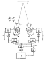
제 2 도는 본 발명의 입체용 프로젝터의 시스템 구성도.2 is a system configuration diagram of a three-dimensional projector of the present invention.
* 도면의 주요부분에 대한 부호의 설명* Explanation of symbols for main parts of the drawings
4 : 좌측 광학계 5 : 우측 광학계4: left optical system 5: right optical system
7 : 좌측렌즈 8 : 우측렌즈7: Left lens 8: Right lens
9 : S편광기 10 : P편광기9: S polarizer 10: P polarizer
11 : 좌측 엘씨디 판넬 12 : 우측 엘씨디 판넬11: Left LCD panel 12: Right LCD panel
13, 14 : 편광기 15, 16 : 콘덴서 렌즈13, 14:
17, 18 : 광원 19, 20 : 반사경17, 18:
23, 26 : 엘씨디 구동부 24, 27 : D/A 컨버터23, 26:
25, 28 : 씨씨디(CCD) 29 : NOT 게이트25, 28: CCD 29: NOT gate
30 : 디멀티 플렉서 31 : A/D 컨버터30: Demultiplexer 31: A / D Converter
32 : 좌우신호 판독기32: left and right signal reader
본 발명은 엘씨디(LCD) 프로젝터의 입체 티브이 시스템에 관한 것으로 특히, 편광(polarizer) 안경에 의해 어둡게 느끼기 쉬운 입체 영상을 선명한 화상으로 볼수 있으며 여러사람이 동시에 시청하기에 적당한 고휘도 입체용 프로젝터 구동장치에 관한 것이다.The present invention relates to a three-dimensional TV system of the LCD (LCD) projector, and in particular, it is possible to see a stereoscopic image that is easy to feel dark by polarizer glasses as a clear image and high brightness three-dimensional projector driver suitable for simultaneous viewing by several people It is about.
종래 입체 티브이 시스템은 제 1 도에 도시된 바와같이, 입체영상을 저장하는 신호원(Signal Source), 폐쇄조절기(Shutting Controller), 좌, 우 액정창 및 브라운관(CRT)등으로 구성된 것으로, 종래 시스템에서는 입체 영상의 원리에 따라 좌, 우측에서 촬영한 영상을 각각 좌우측 눈으로만 볼 수 있도록 함으로 입체적인 영상을 느낄수 있는 것이었다.As shown in FIG. 1, the conventional stereoscopic TV system includes a signal source for storing a stereoscopic image, a closing controller, a left and right liquid crystal window, and a CRT. According to the principle of stereoscopic images, the images taken from left and right can be seen only by the left and right eyes, respectively, so that the stereoscopic images can be felt.
즉, 좌측 카메라에서 촬영한 영상신호가 브라운관(CRT)에 디스플레이될 때 신호원을 받은 콘트롤러는 우측 액정창을 닫아 줌으로써 좌측 눈만으로 왼쪽 영상신호를 볼수 있게하고 이러한 시스템 동작으로 오른쪽 영상신호는 오른쪽 눈으로 볼수 있게 한다.That is, when the video signal taken by the left camera is displayed on the CRT, the controller that receives the signal source can close the right LCD window so that the left video signal can be seen by the left eye only. To see.
그러나, 종래 입체 티브이는 브라운관(CRT)의 밝기가 주사되는 광원에 의존하기 때문에 화면의 밝기가 대체로 어두웠고 시청자가 입체 티브이에 연결되어 동기 작동되는 편광창 안경을 써야할 뿐 아니라 편광창 안경을 쓴 사람만이 입체영상을 볼수 있는 제한성이 있어 효율적으로 사용할 수 없었다.However, the conventional stereoscopic TV is generally dark because the brightness of the CRT depends on the light source to be scanned, and the viewer must wear polarized window glasses that are synchronized to the stereo TV and operate with the polarized window glasses. Only because there is a limitation to see the three-dimensional images could not be used efficiently.
따라서, 본 발명은 종래 입체 티브이의 시스템에서 광원을 접속할 수 있는 좌, 우 광학계를 각각 브라운관(CRT)앞에 설치하여 좌, 우 영상신호의 절환에 따라 빛의 광도를 높혀주도록 구성한 고휘도 입체용 엘씨디 프로젝터 구동장치를 창안한 것으로, 이를 첨부한 도면을 참조하여 상세히 설명하면 다음과 같다.Accordingly, the present invention provides a high brightness three-dimensional LCD projector configured to increase the brightness of light according to the switching of the left and right image signals by installing the left and right optical systems in front of the CRT, respectively, which can be connected to the light source in the conventional stereoscopic TV system. Invented a driving device, which will be described in detail with reference to the accompanying drawings.
제 2 도는 본 발명의 입체용 프로젝터의 시스템 구성도로서 이에 도시한 바와같이, 좌측 및 우측영상신호를 교대로 출력하는 신호원(2)과, 이 신호원(2)의 영상출력이 좌측영상 신호인지 또는 우측영상 신호인지를 판별하는 좌우신호 판독기(32)와, 이 좌우신호 판독기(32)의 출력을 반전시키는 NOT 게이트(29)와, 상기 신호원(2)의 출력을 디지탈 변환한 A/D컨버터(31)의 출력을 상기 좌우신호 판독기(32)의 제어에 따라 역다중화하는 디멀티플렉서(30)와, 상기 좌우 신호 판독기(32) 및 NOT 게이트(29)의 출력에 따라 상기 디멀티 플렉터(30)의 출력을 아날로그 변환함과 아울러 지연출력하는 좌, 우측 광학계 구동부(33)(34)와, 이 좌, 우측 광학계 구동부(33)(34)의 출력에 따라 스크린(16)에 S, P로 편광된 좌, 우 영상신호를 각기 디스플레이하는 좌, 우측 광학계(4)(5)으로 구성한 것으로, 도면의 미설명 부호 21, 22는 편광 안경이다.2 is a system configuration diagram of a three-dimensional projector of the present invention, as shown therein, a
상기 좌측 광학계(4)는 좌측렌즈(7), S편광기(9), 좌측엘씨디판넬(11), 편광기(13), 콘덴서렌즈(15), 광원(17) 및 반사경(19)으로 구성하고 우측광학계(5)는 우측렌즈(8), P편광기(10), 우측 엘씨디판넬(12), 편광기(14), 콘덴서 렌즈(16), 광원(18) 및 반사경(20)으로 구성한다.The left optical system 4 includes a left lens 7, an S polarizer 9, a
상기 좌측 광학계 구동부(33)는 디멀티 플렉서(30)의 일측 출력을 라이트 인에이블 단자(WE)에 좌우신호 판독기(32)의 출력이 접속됨과 아울러 리드 인에이블 단자(RE)에 NOT게이트(29)의 출력이 접속된 씨씨디(CCD)(25)의 입력에 접속하고 이 씨씨디(CCD)(25)의 출력 및 상기 멀티플렉서(30)의 출력을 D/A 컨버터(24)를 통해 엘씨디 구동부(23)에 접속하여 상기 엘씨디 구동부(23)의 출력을 좌측 광학계(4)의 좌측 엘씨디 판넬(11)에 접속하여 구성한다.The left
상기 우측 광학계 구동부(34)는 디멀티플렉서(30)의 타측출력을 라이트 인에이블 단자(WE)에 NOT게이트(29)의 출력이 접속됨과 아울러 리드 인에이블 단자(RE)에 좌우신호 판독기(32)의 출력이 접속된 씨씨디(28)의 입력에 접속하고 이 씨씨디(28)의 출력과 상기 디멀티플렉서(30)의 출력을 D/A 컨버터(27)를 통해 엘씨디 구동부(26)에 접속하여 상기 엘씨디 구동부(26)를 우측광학계(5)의 우측 엘씨디 판넬(12)에 접속하여 구성한다.The right
상기 씨씨디(25)(28)는 SPS(serial-Parallel-Serial)구조로서 라이트 인에이블신호(WE)에 좌, 우측 영상신호를 각기 기록한다.The
이러한 본 발명은 좌, 우측 광학계 구동부(33)(34)에 의해 좌, 우측 엘씨디 판넬(11)(12)에 형성되는 좌, 우측 영상이 S편광기(9)와 편광기(13) 및 P편광기(10)와 편광기(14)에 의해 좌, 우측 렌즈(7)(8)에서 집광된후 스크린(6)위에 각기 S, P편광된 상태로 결상되며, 이 영상은 편광안경(21)(22)에 의해 시청자의 좌측 및 우측눈에 각각의 화상이 입사되어 입체영상을 느끼게 된다.In the present invention, the left and right images formed on the left and
이와같이 구성한 본 발명의 작용 및 효과를 상세히 설명하면 다음과 같다.Referring to the operation and effects of the present invention configured as described above in detail.
본 발명은 좌측 영상의 주사동작을 예를 들어 설명한다.The present invention will be described by taking the scanning operation of the left image as an example.
신호원(2)에서 일정시각에 좌측영상신호가 출력되면 A/D컨버터(31)는 디지탈로 변환하여 디멀티플렉서(30)에 출력하게 되고 좌우신호 판독기(32)는 상기 신호원(2)에서 출력되는 좌, 우측 영상신호를 판독하여 제어 신호를 출력하는데 좌측영상일때 상기 좌우신호 판독기(32)는 "1"인 제어신호를 디멀티플렉서(30) 및 좌, 우측 광학계 구동부(33)(34)에 출력하게 된다.When the left image signal is output from the
이때, 좌우신호 판독기(32)의 고전위 제어신호가 입력된 디멀티플렉서(30)가 A/D컨버터(31)의 좌측영상출력을 좌측광학계 구동부(33)에 출력시키면 D/A컨버터(24)에 입력됨과 아울러 상기 좌우신호 판독기(32)의 고전위 제어신호에 라이트 인에이블된 SPS구조의 씨씨디(25)에 입력되어 좌측영상신호가 기록되어진다.At this time, when the
이에 따라, 좌측광학계 구동부(33)는 D/A컨버터(24)가 디지탈인 좌측영상신호를 아날로그 변환함에 따라 엘씨디 구동부(23)는 좌측광학계(4)의 좌측 엘씨디 판넬(11)을 구동하게 된다.Accordingly, the left
이때, 좌측광학계(4)는 광원(17)이 반사경(19)에서 반사된 후 콘덴서렌즈(15)를 통해 편광기(13)에 입사되고 상기 편광기(13)에서 편광됨 빛은 좌측광학계 구동부(33)에 의해 구동된 좌측 엘씨디 판넬(11)에 주사되어 S편광기(9)에서 S편광된후 좌측렌즈(7)에 집광됨에 따라 스크린(6)에 좌측영상을 주사하게 된다.At this time, the left optical system 4 is incident on the
한편, 우측광학계 구동부(34)는 좌우신호용 판독기(32)의 고전위 제어신호가 입력된 SPS구조의 씨씨디(28)가 리드 인에이블되어 좌측 영상신호가 출력되기 직전에 기록된 우측영상신호를 출력함에 따라 D/A 컨버터(27)를 통해 아날로그 변환되고 이 아날로그 변환된 신호에 의해 엘씨디 구동부(26)는 우측광학계(5)의 우측엘씨디 판넬(12)을 구동하게 된다.On the other hand, the right
이때, 우측광학계(5)는 좌측광학계(4)의 동작과 동일하게 광원(18)이 반사경(20)에 반사된 후 콘덴서렌즈(16), 편광기(14), 우측 엘씨디 판넬(12), P편광기(10) 및 우측렌즈(8)를 순차적으로 통해 주사됨에 따라 스크린(6)에 우측영상을 주사하게 된다.At this time, the right
즉, 신호원(2)에서는 한필드(field)마다 좌, 우 하나의 영상신호가 출력되는데 고휘도를 얻기 위해 좌측영상이 출력되어 스크린(6)에 주사되는 시간에 우측영상(좌측영상신호가 출력되기 직전의 영상 신호)가 상기 스크린(6)에 동시에 주사됨으로 영상주사 동작의 불연속성에 의한 어색함을 제거하여 플리커(flicker) 현상을 방지할 수 있다.That is, in the
이에 따라, 좌우신호 판독기(32)의 제어신호에 의해 좌, 우측 광학계 구동부(33)(34)가 제어되어 좌측광학계(4)는 현재의 좌측영상을, 우측광학계(5)는 현재 좌측영상 직전의 우측영상을 스크린(6)에 주사함으로 전체의 입체 영상이 광원(17)(18)의 토탈 와트(Total Watt)로 밝게 디스플레이 되어진다.Accordingly, the left and right optical
그리고, 신호원(2)이 우측영상을 출력하면 좌우신호 판독기(32)가 저전위 제어신호를 출력하여 디멀티플렉서(30)가 우측영상을 우측광학계 구동부(34)에 출력함에 따라 상기 좌우신호 판독기(32)의 출력이 NOT게이트(29)를 통해 반전되어 입력된 씨씨디(28)에 기록됨과 아울러 D/A컨버터(27)에 입력되고 상기 NOT게이트(29)의 출력이 입력된 좌측광학계 구동부(33)의 씨씨디(25)는 리드인에이블되어 기록된 좌측영상을 D/A컨버터(24)에 출력하게 된다.When the
상기와 같이 신호원(2)의 출력영상에 따라 좌우영상을 기록하고 처리하는 동작을 번갈아 수행하여 스크린(6)에 주사하고 이 영상은 편광안경(21)(22)에 의해 시청자의 좌측 및 우측눈에 입사되어 입체 영상을 느끼게 된다.As described above, the operation of recording and processing the left and right images in accordance with the output image of the
상기에서 상세히 설명한 바와같이 본 발명 고휘도 입체용 엘씨디 프로젝터 구동장치는 좌, 우측 영상신호가 별개의 광원체에 의해 스크린에 각기 주사될뿐 아니라 현재의 좌측영상과 현좌측 영상직전에 디스플레이 되었던 신호를 우측영상으로 스크린에 주사함으로 여러명의 시청자가 편광안경으로 동시에 시청할수 있고 두개의 광원에 의해 밝은 화상을 볼수있는 효과가 있다.As described in detail above, the high-brightness stereoscopic LCD projector driving device of the present invention not only scans the left and right video signals to the screen by separate light sources, but also displays the signals displayed immediately before the current left and left images. By scanning the image on the screen, multiple viewers can watch simultaneously with polarized glasses and the bright image can be seen by two light sources.
Claims (2)
Priority Applications (4)
| Application Number | Priority Date | Filing Date | Title |
|---|---|---|---|
| KR1019870012246A KR930009882B1 (en) | 1987-10-31 | 1987-10-31 | Lcd projector driving device for high brightness |
| US07/263,639 US4954890A (en) | 1987-10-31 | 1988-10-27 | Driving method for 3-D high luminance LCD projector |
| DE3837049A DE3837049A1 (en) | 1987-10-31 | 1988-10-31 | METHOD AND ARRANGEMENT FOR PRODUCING / VIEWING THREE-DIMENSIONAL IMAGES |
| JP63275956A JPH0340592A (en) | 1987-10-31 | 1988-10-31 | Lcd projector driving method for high brightness solid |
Applications Claiming Priority (1)
| Application Number | Priority Date | Filing Date | Title |
|---|---|---|---|
| KR1019870012246A KR930009882B1 (en) | 1987-10-31 | 1987-10-31 | Lcd projector driving device for high brightness |
Publications (2)
| Publication Number | Publication Date |
|---|---|
| KR890007596A KR890007596A (en) | 1989-06-20 |
| KR930009882B1 true KR930009882B1 (en) | 1993-10-12 |
Family
ID=19265696
Family Applications (1)
| Application Number | Title | Priority Date | Filing Date |
|---|---|---|---|
| KR1019870012246A KR930009882B1 (en) | 1987-10-31 | 1987-10-31 | Lcd projector driving device for high brightness |
Country Status (4)
| Country | Link |
|---|---|
| US (1) | US4954890A (en) |
| JP (1) | JPH0340592A (en) |
| KR (1) | KR930009882B1 (en) |
| DE (1) | DE3837049A1 (en) |
Families Citing this family (20)
| Publication number | Priority date | Publication date | Assignee | Title |
|---|---|---|---|---|
| US5502481A (en) * | 1992-11-16 | 1996-03-26 | Reveo, Inc. | Desktop-based projection display system for stereoscopic viewing of displayed imagery over a wide field of view |
| JPH05103349A (en) * | 1991-10-04 | 1993-04-23 | Sony Corp | Visual device |
| US5239372A (en) * | 1991-12-31 | 1993-08-24 | Stereographics Corporation | Stereoscopic video projection system |
| US5347433A (en) * | 1992-06-11 | 1994-09-13 | Sedlmayr Steven R | Collimated beam of light and systems and methods for implementation thereof |
| US5347644A (en) * | 1992-06-11 | 1994-09-13 | Sedlmayr Steven R | Three-dimensional image display device and systems and methods for implementation thereof |
| US5564810A (en) * | 1992-12-31 | 1996-10-15 | Honeywell Inc. | Full color stereoscopic display with color multiplexing |
| US5751341A (en) * | 1993-01-05 | 1998-05-12 | Vista Medical Technologies, Inc. | Stereoscopic endoscope system |
| DE69429933T2 (en) * | 1993-11-09 | 2002-08-29 | Canon Kk | Signal processing device for stereoscopic display device |
| US5523886A (en) * | 1994-01-04 | 1996-06-04 | Sega Of America, Inc. | Stereoscopic/monoscopic video display system |
| US5497270A (en) * | 1994-07-13 | 1996-03-05 | Kaiser Aerospace & Electronics Corporation | Apparatus and method for increasing resolution and expanding the displayed field of view |
| US5933185A (en) * | 1995-05-31 | 1999-08-03 | Sony Corporation | Special effect apparatus |
| US5552821A (en) * | 1995-06-05 | 1996-09-03 | Blonder; Isaac S. | Method of and system for stereoscopic television |
| US6608652B1 (en) * | 1995-10-14 | 2003-08-19 | Semiconductor Energy Laboratory Co., Ltd. | Image display system and method |
| US6570629B1 (en) * | 1995-10-14 | 2003-05-27 | Semiconductor Energy Laboratory Co., Ltd. | Display unit including first and second active matrix regions that is provided completely outside each other |
| US6816158B1 (en) | 1998-10-30 | 2004-11-09 | Lemelson Jerome H | Three-dimensional display system |
| NO308925B1 (en) * | 1999-03-15 | 2000-11-13 | Dimension Technologies As | Method and apparatus for stereo projection of images |
| DE10352492B4 (en) * | 2003-11-07 | 2008-04-03 | Hopp, Armin, Dr.-Ing. | Control for stereo projection |
| US7670004B2 (en) * | 2006-10-18 | 2010-03-02 | Real D | Dual ZScreen® projection |
| US8599247B2 (en) * | 2008-01-30 | 2013-12-03 | Samsung Electronics Co., Ltd. | Stereoscopic image system employing an electronic controller which controls the polarization plane rotator in synchronization with an output image of the display device |
| UA77414U (en) * | 2012-08-17 | 2013-02-11 | Александр Григорьевич Беренок | Method for automatic correction of videoprojections by means of inverse transformation |
Family Cites Families (9)
| Publication number | Priority date | Publication date | Assignee | Title |
|---|---|---|---|---|
| US2883906A (en) * | 1952-02-04 | 1959-04-28 | Rehorn Miles Parker | Stereoscopic system and apparatus |
| JPS57138285A (en) * | 1981-02-19 | 1982-08-26 | Matsushita Electric Ind Co Ltd | Three-dimensional television device |
| US4562463A (en) * | 1981-05-15 | 1985-12-31 | Stereographics Corp. | Stereoscopic television system with field storage for sequential display of right and left images |
| GB8321727D0 (en) * | 1983-08-12 | 1983-09-14 | Brightad Ltd | Producing stereoscopic images |
| JPS6113894A (en) * | 1984-06-29 | 1986-01-22 | Sony Corp | Picture projecter |
| US4654699A (en) * | 1985-07-31 | 1987-03-31 | Antonio Medina | Three dimensional video image display system |
| US4647966A (en) * | 1985-11-22 | 1987-03-03 | The United States Of America As Represented By The Secretary Of The Navy | Stereoscopic three dimensional large screen liquid crystal display |
| DE3623576A1 (en) * | 1986-07-12 | 1988-01-21 | Bosch Gmbh Robert | METHOD AND DEVICE FOR ELECTRONIC TRANSMISSION AND / OR RECORDING AND SUBSEQUENT PLAYBACK OF STEREOSCOPIC TELEVISION IMAGES |
| JPS6331295A (en) * | 1986-07-25 | 1988-02-09 | Canon Inc | Stereoscopic picture signal processor |
-
1987
- 1987-10-31 KR KR1019870012246A patent/KR930009882B1/en not_active IP Right Cessation
-
1988
- 1988-10-27 US US07/263,639 patent/US4954890A/en not_active Expired - Lifetime
- 1988-10-31 DE DE3837049A patent/DE3837049A1/en active Granted
- 1988-10-31 JP JP63275956A patent/JPH0340592A/en active Pending
Also Published As
| Publication number | Publication date |
|---|---|
| JPH0340592A (en) | 1991-02-21 |
| DE3837049A1 (en) | 1989-05-11 |
| DE3837049C2 (en) | 1990-07-19 |
| KR890007596A (en) | 1989-06-20 |
| US4954890A (en) | 1990-09-04 |
Similar Documents
| Publication | Publication Date | Title |
|---|---|---|
| KR930009882B1 (en) | Lcd projector driving device for high brightness | |
| US5581399A (en) | Binoculars | |
| CA2056296C (en) | Video display system | |
| TW509817B (en) | Split image stereoscopic system and method | |
| JPH0775137A (en) | Spectacles for stereoscopic image | |
| JPH06245209A (en) | Camera integrated display device | |
| US6510002B1 (en) | Apparatus for three-dimensional display | |
| JPH09168171A (en) | Display device and its display system | |
| ATE449509T1 (en) | VIDEO SURVEILLANCE SYSTEM FOR A CINEMA FILM CAMERA | |
| JPH08331603A (en) | Shutter system for three-dimensional image | |
| JP2003248195A (en) | Method and system for projecting image | |
| KR20110105830A (en) | Single-sensor juxtaposing type stereo-picture shooting method | |
| JP2003029334A (en) | Liquid crystal projector | |
| JP2957883B2 (en) | 3D effect glasses | |
| KR0141970B1 (en) | Apparatus for transforming image signal | |
| CN111866480B (en) | Light-combined reflector invisible prompter projector system and video data processing method | |
| JPH05103350A (en) | Liquid crystal three-dimensional projector | |
| KR20020022519A (en) | Head Set of Head Mounted Display | |
| KR950006039B1 (en) | Video camera having image projection display function | |
| KR100388392B1 (en) | Head Set of Head Mounted Display | |
| JP2000236561A (en) | Stereoscopic video image display device | |
| JPH02122790A (en) | Stereoscopic video display device | |
| JP2749798B2 (en) | Projection type stereoscopic video playback device | |
| JP3142316B2 (en) | Video stereoscopic image display | |
| KR920010814B1 (en) | Normal state switching circuit of lcd device |
Legal Events
| Date | Code | Title | Description |
|---|---|---|---|
| A201 | Request for examination | ||
| E902 | Notification of reason for refusal | ||
| G160 | Decision to publish patent application | ||
| E701 | Decision to grant or registration of patent right | ||
| GRNT | Written decision to grant | ||
| FPAY | Annual fee payment |
Payment date: 20070918 Year of fee payment: 15 |
|
| EXPY | Expiration of term |