KR930009875B1 - Color detecting circuit - Google Patents
Color detecting circuit Download PDFInfo
- Publication number
- KR930009875B1 KR930009875B1 KR1019850006017A KR850006017A KR930009875B1 KR 930009875 B1 KR930009875 B1 KR 930009875B1 KR 1019850006017 A KR1019850006017 A KR 1019850006017A KR 850006017 A KR850006017 A KR 850006017A KR 930009875 B1 KR930009875 B1 KR 930009875B1
- Authority
- KR
- South Korea
- Prior art keywords
- color
- output
- level
- specific
- red
- Prior art date
Links
Images


Classifications
-
- H—ELECTRICITY
- H04—ELECTRIC COMMUNICATION TECHNIQUE
- H04N—PICTORIAL COMMUNICATION, e.g. TELEVISION
- H04N9/00—Details of colour television systems
- H04N9/64—Circuits for processing colour signals
Landscapes
- Engineering & Computer Science (AREA)
- Multimedia (AREA)
- Signal Processing (AREA)
- Processing Of Color Television Signals (AREA)
- Testing, Inspecting, Measuring Of Stereoscopic Televisions And Televisions (AREA)
Abstract
내용 없음.No content.
Description
제 1 도는 본 발명에 따른 색검출회로를 텔레비젼 수상기에 적용한 경우의 실시예를 도시한 계통도.1 is a schematic diagram showing an embodiment in which the color detection circuit according to the present invention is applied to a television receiver.
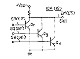
제 2 도는 색검출회로의 실시예를 도시한 계통도.2 is a schematic diagram showing an embodiment of a color detection circuit.
제 3 도는 최소치 연산회로의 실시예를 도시한 접속도.3 is a connection diagram showing an embodiment of a minimum value calculating circuit.
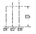
제 4 도는 특정색 검출의 동작설명도.4 is an operation explanatory diagram of specific color detection.
제 5 도는 특정색 검출 출력의 특성도.5 is a characteristic diagram of a specific color detection output.
제 6 도 및 제 7 도는 종래의 기술을 설명하는 계통도.6 and 7 are schematic diagrams illustrating the prior art.
* 도면의 주요부분에 대한 부호의 설명* Explanation of symbols for main parts of the drawings
10 : 색검출회로 10A, 10B : 제 1 및 제 2 색검출수단10:
14 : 감산기 11R 내지 11B : 계수 수단14: subtractor 11R to 11B: counting means
5R 내지 5B : 가산기 VR 내지 VB : 레벨 조정용 볼륨5R to 5B: Adder VR to VB: Volume for adjusting the level
본 발명은 텔레비젼 수상기 등의 화상처리회로의 색 보정시스템에 적용할 수 있는 색 검출회로에 관한 것이다.The present invention relates to a color detection circuit that can be applied to a color correction system of an image processing circuit such as a television receiver.
화상처리에서는 색의 보정이 자주 필요로 하는 경우가 있다.In image processing, color correction is often required.
예를들면 필림의 화상내용을 비디오 신호로 변환하기도 하고, 항공사진을 비디오신호로 변환하기도 하는 경우에, 그들중의 특정의 색을 수정하여 정규의 색으로 하기도 하고, 혹은 특정의 색을 강조한 연후에서 비디오 신호로 변환할 필요가 있다.For example, when converting the picture content of a film into a video signal or converting an aerial photograph into a video signal, after modifying a specific color among them, or after highlighting a specific color, Needs to be converted to a video signal.
또, 텔레비젼 수상기 등에서는 텔레비젼 화상의 특정색을 좋아하는 색으로 보정하고 싶은 경우가 있다.In a television receiver or the like, there is a case where a specific color of a television image is to be corrected to a favorite color.
텔레비젼 수상기를 예를들어 설명하면, 붉은 색을 다른 색보다 강조하고 싶을때는, 제 6 도에 도시한 바와같이 구성하면 된다. 도면에 있어서 단자(1R), (1G), (1B)에 공급된 적 내지 청색의 원색신호를 수상관(CRT)(2)의 대응하는 캐소드(2R 내지 2B)에 공급됨과 동시에, 적신호(SR)의 전송로상에는 색보정회로(3R)가 설치된다.For example, when a television receiver is described, when the red color is to be emphasized more than other colors, it may be configured as shown in FIG. In the drawing, the red to blue primary color signals supplied to the
색 보정회로(3R)는 계수기(4)와 가산기(5)로 구성되고, 계수기(4)의 계수를 적당히 조정함으로서 적신호(SR)가 다른 색신호보다도 레벨이 상승하기 때문에, 화면상에서는 적색성분이 다른 색성분보다도 강조되어서 출력된다.The
적색뿐만 아니라, 다른 색도 동시에 보정하고 싶을때에는 제 7 도에 도시한 바와같이 구성하면 된다.When not only red color but also other colors are desired to be corrected at the same time, the configuration may be performed as shown in FIG.
이 경우에는 3채널의 각각에 색보정회로(3R 내지 3B)를 접속하고, 적당한 색 보정회로를 조정하면 희망하는 색으로 보정할 수가 있다.In this case, if the
그런데, 제 6 도에 도시한 색보정수단에서는 특정의 원색밖에 보정할 수가 없다. 또 제 7 도의 색 보정수단은, 예를들어 살색을 좋아하는 색으로 보정할 수가 있는 반면, 살색과는 전혀 관계가 없는 적 내지 청색의 색성분까지 보정되기 때문에 화면 전체가 살색과 같이 보정되는 결점이 있다.By the way, in the color correction means shown in Fig. 6, only specific primary colors can be corrected. In addition, while the color correction means of FIG. 7 can correct the color to a color like liking, for example, red or blue color components irrelevant to the color are corrected. have.
본 발명은 이와같은 문제점을 해결한 것으로서, 임의의 특정의 색을 보정할 수 있도록 함과 동시에, 기타의 색은 특정의 색에 대해 그 보정량이 적게 되도록 하고, 특정의 색보정에 근거한 다른 색에의 영향을 가능한한 받지 않도록 한 것이다.The present invention has solved such a problem, and it is possible to correct any particular color, while reducing the amount of correction for a specific color, and for other colors based on the specific color correction. As much as possible to avoid the impact of.
그것 때문에, 본 발명에서는 제 1 도에 도시한 바와 같이 특정의 색을 검출할 수 있는 색검출회로(10)를 화상처리의 색 보정시스템에 설치한 것으로서, 이것은, 제 2 도에 도시한 바와같이 제1의 색검출수단(10A)과, 제2의 색 검출수단(10B)을 가지고 있고, 제1의 색 검출수단(10A)으로 백색성분을 중심으로 하는 제1의 색 검출출력(EW)을 얻고, 제2의 색검출수단(10B)으로 검출해야할 특정의 색을 포함하는 색성분을 중심으로 하는 제2의 색 검출출력(ES)을 얻고, 그들의 감산출력(EO)을 특정색 검출출력으로서 사용한다(제 5 도 참조).For this reason, in the present invention, as shown in Fig. 1, a
이 특정색 검출출력(EO)으로 특정의 채널을 제어하다.The specific color detection output EO controls a specific channel.
특정색 검출출력(EO)은 특정의 색일때 최대의 레벨로되고, 특정의 색으로부터 벗어남에 따라 그 레벨이 저하하는 것과 같은 출력으로 되기 때문에, 특정의 색신호가 공급되었을때만 그 색이 강조되기도 하고, 역으로 완화되고, 기타의 색신호가 공급되었을 때에는 그 색신호의 보정량이 적기 때문에, 기타의 색에 대한 영향은 아주 적다.The specific color detection output (EO) is at the maximum level for a specific color, and the output is such that the level decreases as the color shifts away from the specific color. Therefore, the color is emphasized only when a specific color signal is supplied. When the other color signal is supplied, the amount of correction of the color signal is small. Therefore, the influence on the other color is very small.
또, 특정의 색은 살색 등의 중간색도 검출할 수가 있다.In addition, the specific color can also detect intermediate colors such as flesh color.
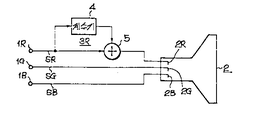
제 1 도는 본 발명에 따른 색 검출회로(10)의 한 실시예를 도시한 것으로서, 이 예는 제 7 도에 도시한 텔레비젼 수상기에 있어서의 살색의 보정계에 적용한 경우이다.FIG. 1 shows an embodiment of the
제 1 도에 있어서 단자(1R 내지 1B)에 공급된 적 내지 청신호(SR 내지 SB)(그 진폭레벨(ER 내지 EB)은 CRT(2)의 대응하는 캐소드(2R 내지 2B)에 공급됨과 동시에, 이들 적 내지 청신호(SR 내지 SB)는 색검출회로(10)에 공급되고, 그 특정색 검출출력(EO)은 보정레벨 조정용의 수단, 본 실시예에서는 볼륨(VR 내지 VB)을 통하여 각 채널에 설치된 신호 합성용의 가산기(5R 내지 5B)에 공급된다.In FIG. 1, the red to blue signals SR to SB (the amplitude levels ER to EB) supplied to the
색 검출회로(10)는 제 2 도에 도시한 바와 같이, 제1 및 제2의 색검출수단(10A),(10B)과 감산기(14)로 구성되고, 제1의 색검출수단(10A)는 본 예에서는 최소연산회로가 사용된다. 제2의 색검출수단(10B)은 각각의 채널에 설치된 계수수단(11R 내지 11B)와 최소치 연산회로(12)로 구성된다.The
최소치 연산회로(10A), (12)는 제 3 도에 도시된 바와같이 에미터 및 콜렉터 공통의 PNP형의 트랜지스터(Qr 내지 Qb)를 가지고 있고, 각각의 베이스에 적 내지 청신호(SR 내지 SB)가 공급되고, 그 공통 에미터부터 출력단자 OUT가 도출된다.The
트랜지스터(Qr 내지 Qb)는 적 내지 청신호(SR 내지 SB)중 최소 레벨의 신호가 공급된 트랜지스터만은 온으로 하기 때문에, 출력단자 OUT에서 적 내지 청신호(SR 내지 SB)중 최소 레벨의 신호가 출력하게 된다.Since the transistors Qr to Qb turn on only the transistors to which the minimum level of the red to blue signals SR to SB are supplied, the signal of the minimum level of the red to blue signals SR to SB is output at the output terminal OUT. Done.
계수 수단(11R 내지 11B)의 각 계수 K1 내지 K3는 최종적으로 검출하려는 특정의 색에 따라서 정해지는 정규수단이며, 검출하려는 특정의 색이 입력되었을때, 정규화된 적 내지 청신호(SR' 내지 SB')의 각 레벨(ER' 내지 EB')이 동등하게 되도록 선택되고 또한, 간단하게 하기 위하여 최소치가 1로 되도록 정규화된다. 살색을 검출하려고 하는 경우에는 살색일때의 각 레벨(ER 내지 EB)의 비율을 KR 내지 KB로 한다면,The coefficients K1 to K3 of the counting means 11R to 11B are regular means determined in accordance with the specific color to be finally detected, and when the specific color to be detected is input, normalized red to blue signals SR 'to SB' Each level (ER 'through EB') is selected to be equal and normalized so that the minimum value is 1 for simplicity. When trying to detect flesh color, if the ratio of each level (ER to EB) at the time of flesh color is KR to KB,
![]()
![]()
로 된다. 여기서It becomes here

이다. 살색인 경우, 황색살을 기준으로 하면to be. In the case of flesh color,

정도이기 때문에, 계수수단(11R 내지 11B)의 각 계수 K1~K3는 다음과 같이 설정된다.Because of the accuracy, the coefficients K 1 to K 3 of the counting means 11R to 11B are set as follows.

그런데, 입력단자(1R 내지 1B)에 공급되는 적 내지 청신호(SR 내지 SB)의 레벨(ER 내지 EB)로서 제 4a 도 내지 4d 도에 도시한 것을 입력된 것으로 한다면, 최소치 연산회로(10A, 12)로부터 다음과 같은 제1 및 제2의 색검출 출력(EW, EW)이 얻어진다.By the way, if the ones shown in Figs. 4A to 4D are input as the levels ER to EB of the red to blue signals SR to SB supplied to the
제 4a 도는 살색일때의 레벨관계(ER : EG : EB=1 : 0.85 : 0.7)를 도시하며, 제 4b 도는 백색일 때의 레벨관계(ER : EG : EB=1 : 1 : 1)를 도시하고, 제 4c 도는 다른 임의의 색일때의 레벨관계(본 예에서는, ER=EB〉EG)를 도시하며, 제 4d 도는 청색만이 입력하였을 때의 레벨관계(ER=EG=0, EB=1.0)를 도시하고 있다.FIG. 4a shows the level relationship (ER: EG: EB = 1: 0.85: 0.7) when flesh is present, and FIG. 4b shows the level relationship (ER: EG: EB = 1: 1: 1) when white. Fig. 4c shows a level relationship (ER = EB > EG) in the case of any other color, while figure 4d shows a level relationship (ER = EG = 0 and EB = 1.0) when only blue is input. It is shown.
제1의 색검출수단(10A)에 있어서는 각각의 채널에, 제2의 색 검출수단(10B)에 있어서와 같은 계수 수단(11R 내지 11B)이 설치되어 있지 않기 때문에, 각 채널의 계수는 모두 1이다. 따라서, 제 4a 도 내지 제 4d 도에 도시된 신호(SR 내지 SB)가 입력되었을때 제 4e 도 내지 제 4h 도에 파선으로 도시된 것과 같이, 입력신호 레벨(ER 내지 EB)그 자체중의 최소 레벨을 가지는 신호가 출력된다. 동 제 4a 도의 경우에는 청신호(SB)가 출력되고, 이것이 제1의 색 검출출력(EW)으로서 사용된다.In the first color detecting means 10A, since the same counting means 11R to 11B as in the second color detecting means 10B are not provided in each channel, the coefficients of each channel are all one. to be. Therefore, when the signals SR to SB shown in FIGS. 4A to 4D are inputted, as shown by the broken lines in FIGS. 4E to 4H, the minimum among the input signal levels ER to EB itself. A signal having a level is output. In the case of FIG. 4A, the blue signal SB is output, which is used as the first color detection output EW.
제 4b 도에서는 동일 레벨로 입력하기 때문에, 어느 하나의 신호(예를들면 적신호 SR)가 출력된다. 이와같이, 제 4c 도의 경우에는 녹색신호(SG)가 출력되고, 제 4d 도에서는 제1의 색검출출력(EW)은 영으로 된다.In FIG. 4B, since the signal is input at the same level, any one signal (for example, red signal SR) is output. Thus, in the case of FIG. 4C, the green signal SG is output, and in FIG. 4D, the first color detection output EW is zero.
그리고, 제 4e 도 내지 4h 도부터 명백히 도시된 것과 같이, 제1의 색검출수단(10A)으로부터의 백색일때 최대의 레벨로, 백색으로부터 벗어나는 색성분을 가진 신호가 입력되었을 때에는 그 출력레벨이 저하되고, 포화도 100%의 단색 또는 2색으로 이루어진 중간색이 입력되었을 때에는, 그 출력레벨이 영으로 되는 출력이 얻어진다. 따라서, 제1의 색검출 출력(EW)은 제 5 도 곡선(LW)에 표시된 것과 같은 삼각파형의 출력곡선으로 된다. a점, b점은 포화도 100%의 단색 또는 2색으로 이루어진 중간색을 나타낸다.4E to 4H, the output level is lowered when a signal having a color component deviating from the white is input at the maximum level when it is white from the first color detection means 10A. When a single color or a middle color composed of two colors of 100% saturation is input, an output in which the output level is zero is obtained. Therefore, the first color detection output EW becomes a triangular waveform output curve as shown in FIG. 5 curve LW. A point and b point represent the intermediate color which consists of a single color or two colors of 100% of saturation.
이것에 대하여, 제2의 색검출수단(10B)에 있어서는 계수수단(11R 내지 11B)이 설치되어 있기 때문에, 제 4a 도 내지 4d 도에 도시된 레벨관계를 가지는 신호(SR 내지 SB)가 입력되었을지라도, 각각에서 얻어지는 정규화 후의 신호(SR' 내지 SB')의 레벨(ER' 내지 EB')은 제 4i 도 내지 4l 도와 같이 된다. 살색인 때는 정규화에 의하여 각 레벨(ER' 내지 EB')은 동등하게 되고(제 4i 도), 백색일때는 제 4j 도로 되고, 제 4c 도, 4d 도의 색입력 때는 제 4k 도, 4l 도와 같이 된다.On the other hand, since the counting means 11R to 11B are provided in the second color detection means 10B, the signals SR to SB having the level relationship shown in Figs. 4A to 4D are inputted. However, the levels ER 'through EB' of the normalized signals SR 'through SB' obtained at each become as shown in Figs. 4I through 4L. Normally, each level (ER 'through EB') becomes equal when the skin is colored (FIG. 4i), and when the color is white, it becomes the 4j degree. .
여기서, 살색일때의 정규화된 레벨(ER' 내지 EB')의 최소치와, 백색일때의 레벨(ER')은 동등하게 되고, 더우기 그 레벨은 제 4f 도에 도시된 출력레벨(EW)과 동등하게 된다. 또 입력색성분이 살색에서 벗어남에 따라서 그 출력 레벨이 저하하고, 포화도 100%의 단색 또는 2색일때는 영으로 되기 때문에, 제2의 색 검출출력(ES)은 제 5 도 곡선(LS)과 같은 사다리꼴 파형의 출력곡선으로 된다.Here, the minimum value of the normalized levels (ER 'to EB') in flesh color, and the level (ER ') in white color are equal, and the level is equal to the output level (EW) shown in FIG. 4F. do. In addition, as the input color component is out of the skin color, its output level decreases and becomes zero when it is monochromatic or two-color with 100% saturation. Therefore, the second color detection output ES is equal to the fifth degree curve LS. The output curve of the trapezoidal waveform becomes.
그리고, 감산기(14)에 있어서, 제2의 색 검출출력(ES)으로부터 제1의 색 검출출력(EW)이 감산되기 때문에, 감산출력(EO)은 제 5 도의 곡선(LO)으로 도시된 바와같이 삼각파형의 출력곡선으로 된다. 즉 살색일때 최대이고, 살색으로부터 백색으로 벗어남에 따라서 그 레벨이 감소하고, 백색에서 영으로되고, 또 살색부터 백색이외의 방향으로 벗어나는 경우에는 똑같이 감소하고, b점에서 영으로 된다.In the
이와 같이, 감산출력(EO)은 살색입력때만 최대의 레벨로 되기 때문에 색검출회로(10)에 의하여 특정의 색이 검출할 수 있게 되고, 감산 출력(EO)은 특정색 검출출력으로서 이용된다.In this way, since the subtracted output EO is at the maximum level only at the skin color input, the specific color can be detected by the
따라서, 지금 살색으로서 다소 적색이 낀 살색으로 보정하고 싶을 때에는, G, B 채널용의 보정 볼륨(VG, VB)을 최소치로 조정하고, 가산기(5G), (5B)에 가해지는 특정색 검출출력(EO)을 영으로 하고, 채널보정용의 볼륨(VR)를 조정하여 레벨조정된 특정색 검출출력(EO)를 가산기(5R)에 가하면, 송상(送像)측의 살색보다 약간 적색이 낀 살색으로 보정된다.Therefore, when it is desired to correct the skin color slightly red as the flesh color, the specific volume detection output applied to the
이때, 살색을 나타내는 신호 이외의 적, 녹, 청 신호가 공급될 때에도, 제 5b 도에 도시된 특정색검출출력(EO)이 얻어지고, R채널에 그 특정색 검출출력(EO)이 가산되지만, 이때의 EO자체 레벨이 작고, 또 볼륨(VR)에 의해서 그 레벨이 다시 조정되기 때문에, R채널에 특정색 검출출력(EO)이 가산되어도 살색 이외의 색이 두드러지게 적색을 띄는 경우가 없다. 또, 백색일때는 EO=0으로 되기 때문에, 이때는 R채널의 보정량도 영으로 되고, 백색 밸런스를 파괴시키지 않는다.At this time, even when red, green, and blue signals other than the color signal are supplied, the specific color detection output EO shown in FIG. 5B is obtained, and the specific color detection output EO is added to the R channel. At this time, since the EO itself level is small and the level is adjusted again by the volume VR, a color other than flesh color does not become noticeably red even when a specific color detection output EO is added to the R channel. . When EO is white, the correction amount of the R channel is also zero at this time, and the white balance is not destroyed.
살색을 기타 좋아하는 살색으로 보정할 경우에는, 그 좋아하는 색에 따라서 볼륨(VR 내지 VB)의 레벨을 조정하면 되고, 또 살색 이외의 특정의 색을 조정하고 싶을 때에는 계수수단(11R 내지 B)의 계수를 변경하면 된다.When the flesh color is corrected to other favorite flesh color, the level of the volumes VR to VB may be adjusted according to the favorite color, and when counting specific colors other than the flesh color, the counting means 11R to B are used. Just change the coefficient of.
따라서, 본 발명을 텔레비젼 수상기 이외의 화상처리의 색보정계, 예를들면 필림화상을 비디오 신호로 변환하는 변환계에 설치되는 색보정계에 적용하는 경우에도, 수정 또는 강조하여야 할 특정색을 검출하여야 할 계수수단(11R 내지 11B)의 계수를 설정하면, 수정하여야할 특정의 색을 나타내는 색신호가 입력하였을 때 최대의 레벨로 되는 것과 같은 특정색검출출력(EO)이 얻어지기 때문에, 볼륨(VR 내지 VB)을 조정함으로서 특정의 색을 수정 또는 강조할 수가 있다.Therefore, even when the present invention is applied to a color correction system for image processing other than a television receiver, for example, a color correction system installed in a conversion system for converting a film image into a video signal, a specific color to be corrected or emphasized should be detected. By setting the coefficients of the counting means 11R to 11B, since the specific color detection output EO such that the color signal representing the specific color to be corrected is attained to the maximum level is obtained, the volumes VR to VB are obtained. ) To adjust or emphasize a particular color.
이상 설명한 바와같이, 본 발명에 의하여, 특정의 색일때 최대의 레벨로 되고, 특정의 색으로부터 벗어남에 따라 그 레벨이 저하하는듯 특정색검출출력(EO)이 얻어지기 때문에, 특정의 색신호가 공급되었을때만이 그 색이 강조되기도 하고, 역으로 완화되고, 기타의 색신호가 공급되었을때에는 그 색신호의 보정량이 적게 되기 때문에, 기타의 색에 의한 영향은 아주 적다.As described above, according to the present invention, the specific color detection output EO is obtained as the maximum level is obtained when a specific color is obtained and the level is lowered as the level is lowered as a deviation from the specific color. When the color is emphasized only, the color is emphasized and reversed, and when the other color signal is supplied, the correction amount of the color signal is small, so the influence of the other color is very small.
그 때문에, 종래와 같이 특정의 원색밖에 보정할 수 없고, 예를들면 살색을 좋아하는 살색으로 보정하면, 살색과는 전혀 관계가 없는 적 내지 청색의 색성분까지 보정되어 버리는 결점을 없앨 수 있는 특징을 가지고 있다.Therefore, only a specific primary color can be corrected as in the prior art. For example, if a color is preferred to a flesh color, the defect can be eliminated from red to blue color components that have nothing to do with flesh color. Have.
Claims (1)
Applications Claiming Priority (2)
| Application Number | Priority Date | Filing Date | Title |
|---|---|---|---|
| JP59173599A JPS6152093A (en) | 1984-08-21 | 1984-08-21 | Color detecting circuit |
| JP173599 | 1984-08-21 |
Publications (2)
| Publication Number | Publication Date |
|---|---|
| KR860002205A KR860002205A (en) | 1986-03-26 |
| KR930009875B1 true KR930009875B1 (en) | 1993-10-12 |
Family
ID=15963586
Family Applications (1)
| Application Number | Title | Priority Date | Filing Date |
|---|---|---|---|
| KR1019850006017A KR930009875B1 (en) | 1984-08-21 | 1985-08-21 | Color detecting circuit |
Country Status (2)
| Country | Link |
|---|---|
| JP (1) | JPS6152093A (en) |
| KR (1) | KR930009875B1 (en) |
Families Citing this family (2)
| Publication number | Priority date | Publication date | Assignee | Title |
|---|---|---|---|---|
| US5091258A (en) * | 1990-08-20 | 1992-02-25 | Monsanto Company | Laminate for a safety glazing |
| JP2546071Y2 (en) * | 1991-04-15 | 1997-08-27 | 株式会社大林組 | Bridge girder damping device |
-
1984
- 1984-08-21 JP JP59173599A patent/JPS6152093A/en active Granted
-
1985
- 1985-08-21 KR KR1019850006017A patent/KR930009875B1/en not_active IP Right Cessation
Also Published As
| Publication number | Publication date |
|---|---|
| JPH0570987B2 (en) | 1993-10-06 |
| JPS6152093A (en) | 1986-03-14 |
| KR860002205A (en) | 1986-03-26 |
Similar Documents
| Publication | Publication Date | Title |
|---|---|---|
| EP0172754B1 (en) | Color correction circuit | |
| US4240103A (en) | Method for the additive and multiplicative spurious signal compensation | |
| US4035835A (en) | System for automatic correction of the color balance between the primary signals of a color signal source | |
| US4480266A (en) | Method and apparatus for preventing generation of false color signals in color television cameras | |
| KR920006173B1 (en) | Apparatus for correcting errors in color signal transitions | |
| KR970007799B1 (en) | Luminance signal forming circuit | |
| US4167750A (en) | Color-difference signal modifying apparatus | |
| US4157566A (en) | Single tube color television camera with color correction | |
| US4458263A (en) | Video signal processing circuit for a color television receiver | |
| KR930009875B1 (en) | Color detecting circuit | |
| US5150206A (en) | Video display system using an improved color signal technique | |
| US4489344A (en) | Signal processing unit | |
| CA1162298A (en) | Color temperature control circuit | |
| US3281528A (en) | Colour television system including means for separately deriving the luminance component | |
| KR930009877B1 (en) | Dinamic color compensation circuit | |
| US2823254A (en) | Color television receiver | |
| US5889565A (en) | Method and apparatus for improving the color rendition of color television receivers | |
| US4346400A (en) | Matrix circuits | |
| US3246078A (en) | Colour television receivers | |
| GB1062959A (en) | Improvements in or relating to circuit arrangements for use in colour television receivers | |
| JPS5648790A (en) | Color television camera | |
| US3961362A (en) | Dynamic hue control networks | |
| JPS5819089A (en) | Luminance signal correcting system for color television camera | |
| JPS633592A (en) | Video camera | |
| Onishi et al. | New IC family for a single-tube color video camera |
Legal Events
| Date | Code | Title | Description |
|---|---|---|---|
| A201 | Request for examination | ||
| E902 | Notification of reason for refusal | ||
| G160 | Decision to publish patent application | ||
| E701 | Decision to grant or registration of patent right | ||
| GRNT | Written decision to grant | ||
| FPAY | Annual fee payment |
Payment date: 20040914 Year of fee payment: 12 |
|
| EXPY | Expiration of term |