KR930005958B1 - Control device for an internal combustion engine - Google Patents
Control device for an internal combustion engine Download PDFInfo
- Publication number
- KR930005958B1 KR930005958B1 KR1019890010729A KR890010729A KR930005958B1 KR 930005958 B1 KR930005958 B1 KR 930005958B1 KR 1019890010729 A KR1019890010729 A KR 1019890010729A KR 890010729 A KR890010729 A KR 890010729A KR 930005958 B1 KR930005958 B1 KR 930005958B1
- Authority
- KR
- South Korea
- Prior art keywords
- parameter
- internal combustion
- combustion engine
- value
- engine
- Prior art date
Links
Images


Classifications
-
- F—MECHANICAL ENGINEERING; LIGHTING; HEATING; WEAPONS; BLASTING
- F02—COMBUSTION ENGINES; HOT-GAS OR COMBUSTION-PRODUCT ENGINE PLANTS
- F02D—CONTROLLING COMBUSTION ENGINES
- F02D41/00—Electrical control of supply of combustible mixture or its constituents
- F02D41/30—Controlling fuel injection
- F02D41/32—Controlling fuel injection of the low pressure type
- F02D41/36—Controlling fuel injection of the low pressure type with means for controlling distribution
-
- F—MECHANICAL ENGINEERING; LIGHTING; HEATING; WEAPONS; BLASTING
- F02—COMBUSTION ENGINES; HOT-GAS OR COMBUSTION-PRODUCT ENGINE PLANTS
- F02D—CONTROLLING COMBUSTION ENGINES
- F02D35/00—Controlling engines, dependent on conditions exterior or interior to engines, not otherwise provided for
- F02D35/02—Controlling engines, dependent on conditions exterior or interior to engines, not otherwise provided for on interior conditions
- F02D35/023—Controlling engines, dependent on conditions exterior or interior to engines, not otherwise provided for on interior conditions by determining the cylinder pressure
-
- F—MECHANICAL ENGINEERING; LIGHTING; HEATING; WEAPONS; BLASTING
- F02—COMBUSTION ENGINES; HOT-GAS OR COMBUSTION-PRODUCT ENGINE PLANTS
- F02D—CONTROLLING COMBUSTION ENGINES
- F02D35/00—Controlling engines, dependent on conditions exterior or interior to engines, not otherwise provided for
- F02D35/0007—Controlling engines, dependent on conditions exterior or interior to engines, not otherwise provided for using electrical feedback
-
- F—MECHANICAL ENGINEERING; LIGHTING; HEATING; WEAPONS; BLASTING
- F02—COMBUSTION ENGINES; HOT-GAS OR COMBUSTION-PRODUCT ENGINE PLANTS
- F02D—CONTROLLING COMBUSTION ENGINES
- F02D41/00—Electrical control of supply of combustible mixture or its constituents
- F02D41/02—Circuit arrangements for generating control signals
- F02D41/04—Introducing corrections for particular operating conditions
- F02D41/10—Introducing corrections for particular operating conditions for acceleration
-
- F—MECHANICAL ENGINEERING; LIGHTING; HEATING; WEAPONS; BLASTING
- F02—COMBUSTION ENGINES; HOT-GAS OR COMBUSTION-PRODUCT ENGINE PLANTS
- F02D—CONTROLLING COMBUSTION ENGINES
- F02D41/00—Electrical control of supply of combustible mixture or its constituents
- F02D41/30—Controlling fuel injection
- F02D41/32—Controlling fuel injection of the low pressure type
Abstract
내용 없음.No content.
Description
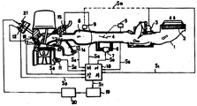
제1도는 이 발명의 한 실시예인 제어장치의 전체구성을 타나내는 개요도.1 is a schematic diagram showing an overall configuration of a control device according to one embodiment of the present invention.
제2도는 제1도의 요부구성을 나타내는 블록도.2 is a block diagram showing the main components of FIG.
제3도는 제1도의 연소압(燃燒壓)센서(13)에 의하여 측정한 연소압 파형의 일례를 나타내는 도면.3 is a diagram showing an example of a combustion pressure waveform measured by the combustion pressure sensor 13 of FIG.
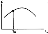
제4도는 연소압에 관계되는 파라미터의 과도시의 변화모양을 나타내는 도면.FIG. 4 is a diagram showing a change pattern of over-drawing of parameters related to combustion pressure. FIG.
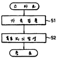
제5도 및 제6도는 이 발명을 제어하기 위한 플로챠트.5 and 6 are flowcharts for controlling this invention.
제7도 및 제8도는 연소압에 관계되는 파라미터와 연료분사밸브 구동펄스폭 및 점화시기의 관계를 나타내는 도면.7 and 8 are diagrams showing a relationship between a parameter related to combustion pressure, a fuel injection valve driving pulse width, and an ignition timing;
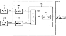
제9도는 이 발명에 의한 제어장치의 기능편성을 표시한 블럭도.9 is a block diagram showing the functional combination of a control device according to the present invention.
* 도면의 주요부분에 대한 부호의 설명* Explanation of symbols for main parts of the drawings
3 : 에어플로미터 7 : 바이패스 밸브3: air flow meter 7: bypass valve
9 : 흡기관압력센서 12 : 크랑크각센서9 Intake pipe pressure sensor 12 Crank angle sensor
14 : 배기센서 15 : 연료분사밸브14 exhaust sensor 15 fuel injection valve
16 : 점화플러그 17 : 연소압센서16
18 : 제어장치18: controller
이 발명은 내연기관의 연료공급량 점화시기 혹은 흡입공기량을 기관의 과도운전 상태에서 제어하는 제어장치에 관한 것이다. 기관의 흡입공기량 도는 흡기관 압력과 회전수의 관계를 바탕으로 하여 적정한 연료공급량이나 점화시기를 연산하여 연료분사밸브와 점화장치를 제어하는 장치가 종래로 부터 사용되고 있다.This invention relates to the control apparatus which controls the fuel supply amount ignition timing or the intake air amount of an internal combustion engine in the over-driving state of an engine. Background Art An apparatus for controlling a fuel injection valve and an ignition device by calculating an appropriate fuel supply amount or an ignition timing based on the relationship between the intake air amount of the engine and the intake pipe pressure and rotation speed has been conventionally used.
또, 기관의 연소압력을 검출하고 이것을 미리 정해진 값으로 조정하여 더욱 정밀도 높은 제어를 행할 수 있는 것을 목적으로하는 제어장치가 일본국 특개소 62-85148에 제안되어 있다.Moreover, a control apparatus for the purpose of detecting the combustion pressure of an engine and adjusting it to a predetermined value to perform more precise control is proposed by Unexamined-Japanese-Patent No. 62-85148.
이러한 제어장치는 각 기통에 설치된 통내압(연소압)센서의 출력에 의하여 연소상태를 검출하고, 이 상태가 미리 정해진 패턴에 적합하도록 연소분사시기나 EGR밸브등을 제어하는 것이다.Such a control apparatus detects a combustion state by the output of the cylinder pressure (combustion pressure) sensor provided in each cylinder, and controls a combustion injection timing, an EGR valve, etc. so that this state may conform to a predetermined pattern.
이와같은 종래장치에서는 연소압을 제어하는 파라미터로서 연료분사시기나, EGR율을 사용하고 있지만, 이와같은 파라미터로 연소압을 제어할수 있는 범위는 지극히 좁으며 특히 운전상태가 급변하는 자동차용 기관에 있어서는 연소상태의 변동폭이 크기때문에 상기 조작파라미터에 의하여 항상 최적한 연소상태를 얻을 수 없었던 것이다.In the conventional apparatus, the fuel injection timing and the EGR rate are used as the parameters for controlling the combustion pressure. However, the range in which the combustion pressure can be controlled using these parameters is extremely narrow, and especially in an engine for a vehicle in which the driving condition changes rapidly. Since the fluctuation range of the combustion state was large, the optimum combustion state could not always be obtained by the operation parameter.
이 발명은 이러한 문제점을 해결하기 위하여 발명된 것으로서 기관의 과도상태에 있어서도 충분한 제어성이 있는 동시에 연소상태의 변화범위도 최적이 되도록 제어 하여 스므스한 가감속(加減速) 성능을 얻을수 있는것을 목적으로 한다.The present invention has been invented to solve these problems, and aims to obtain smooth acceleration and deceleration performance by controlling the engine to have an optimal control over the transient state of the engine and at the same time the change in the combustion state. do.
이 발명에 의한 내연기관의 제어장치에 있어서는 기관의 연료공급량(인젝터가 설치된 기관의 경우에 연료분사 밸브의 구동펄스폭에 대응하는), 점화시기 및 흡기량 중 적어도 하나를 변수로서 선택한다. 기관의 기통내의 연소압으로 부터 연산되고 기관의 출력을 표시하는 파라미터의 설계치를 예를들어 기관의 스로틀 밸브 개도의 변화율로 부터 판정되는 그 목표치와 비교한다. 변수는 파라미터의 실제치와 목표치간의 차가 감소되도록 제어된다.In the control apparatus of the internal combustion engine according to the present invention, at least one of the fuel supply amount (corresponding to the drive pulse width of the fuel injection valve in the case of the engine injector installed), the ignition timing, and the intake air amount are selected as variables. The design value of the parameter calculated from the combustion pressure in the engine cylinder and indicating the engine output is compared with the target value determined, for example, from the rate of change of the engine throttle valve opening. The variable is controlled such that the difference between the actual value and the target value of the parameter is reduced.
이와같이 연소사이클마다 연소압의 증감도를 목표치로 제어함으로써 기관의 과도운전상태에 있어서도 스므스한 가감속이 가능하게 된다.By controlling the increase and decrease of the combustion pressure for each combustion cycle in this manner, a smooth acceleration and deceleration is possible even in an excessive driving state of the engine.
이 발명을 한 실시예인 도면에 의하여 상세하게 설명한다.This invention is demonstrated in detail by drawing which is an Example.
제1도에 있어서, 1은 흡입공기를 안내하는 흡기과, 2는 흡기관(1)의 공기 취입구에 설치된 에어클리너, 3은 에어클리너(2)를 통하여 흡입되는 흡입공기량을 계측하는 에어플로미터, 4는 엑셀페달의 조작에 의하여 회전되고, 흡기관(1)을 통하여 흡입되는 흡입공기량을 조정하는 스로틀밸브, 5는 스로틀밸브(4)의 회전위치 즉 밸브개도(開度)을 검출하는 개도센서, 6은 스로틀밸브(4)를 바이패스시켜 흡입공기를 공급시키는 바이패스통로, 7은 바이패스통로(6)에 설치되고 바이패스 공기량을 조정하는 바이패스밸브, 8은 흡기매니폴드, 9는 흡기매니폴드(8)에 설치되고 흡기관내의 압력을 검출하는 압력센서이다.In FIG. 1, 1 is an intake air for guiding intake air, 2 is an air cleaner installed at an air inlet of the
또한, 10은 기관본체, 11은 기관본체(10)를 구성시키는 실린더 블록에 부착되고 기관을 냉각시키는 냉각수의 온도를 검출하는 수온센서, 12는 기관의 회전위치를 나타내는 크랭크각을 검출하는 크랭크각센서로서, 예컨데 크랭크각의 기준위치(4기통기관에서는 180도, 6기통기관에서는 120도)마다 기준위치 펄스를 단위각도(예컨데 1도)마다 단위각펄스를 각각 발생시키는 것이며 기준위치펄스후의 단위각펄스를 계수함으로써 크랭크각을 검출할수 있음과 동시에 단위각펄스의 주파수 또는 주기를 계측함으로써 기관의 회전속도를 검출할 수 있다.In addition, 10 is the engine body, 11 is a water temperature sensor attached to the cylinder block constituting the engine body 10 and detects the temperature of the cooling water for cooling the engine, 12 is a crank angle for detecting the crank angle indicating the rotational position of the engine As a sensor, for example, a reference position pulse is generated for each reference position of the crank angle (180 degrees for 4 cylinder engines and 120 degrees for 6 cylinder engines), and a unit angle pulse is generated for each unit angle (for example, 1 degree). The crank angle can be detected by counting the angular pulses, and the rotational speed of the engine can be detected by measuring the frequency or period of the unit angle pulses.
또 13은 기관의 연소가스를 배출시키기위한 배기매니폴드, 14는 배기통로에 설치되고 배기가스의 성분농도 예컨데 산소농도를 검출하는 배기센서, 15는 기관내에 연료를 공급하는 연료분사밸브, 16은 연료에 착화시키는 점화플러그, 17은 실린더내압력 즉 연소압을 검출하는 연소압센서, 18은 각종센서의 신호에 의하여 제어신호를 발생시키는 제어장치, 19는 제어장치(18)의 출력인 점화시기 신호를 증폭시키는 파워 유니트, 20은 파워유니트(19)에 의하여 구동되고 고전압을 발생시키는 점화 코일 21은 점화코일(20)에 의한 고전압을 각기통에 설치된 점화플러그(16)에 분배시키는 디스트리뷰터이다.13 is an exhaust manifold for exhausting the combustion gas of the engine, 14 is an exhaust sensor installed in the exhaust passage for detecting the component concentration of the exhaust gas, for example oxygen concentration, 15 is a fuel injection valve for supplying fuel to the engine, An ignition plug for ignition of fuel, 17 is a combustion pressure sensor for detecting in-cylinder pressure, that is, combustion pressure, 18 is a control device for generating a control signal according to signals of various sensors, and 19 is an ignition timing which is an output of the
제1도의 엔진동작은 제어장치(18)에 의하여 제어되며 이 제어장치는 각종센서 신호에 응답하여 필요한 제어신호를 출력한다. 구체적으로 설명하면 제어장치(18)에 입력되는 신호는 흡기량 Qa를 표시하는 에어플로미터(3)의 출력신호 또는 교호로 흡기압 Pb를 표시하는 압력센서(9)의 신호 Sla, 스로틀밸브(4)의 개도α를 표시하는 스로틀개도센서(5)의 출력신호 S5기관의 냉각수 온도를 표시하는 수온센서(11)의 출력신호 S2, 기관의 크랭크각 θc와 rpm N을 표시하는 크랭크각 센서(12)의 출력신호 S3,기관의 실린더 내압 Pc을 표시하는 연소압 센서(17)의 출력신호 S8, 배기가스의 성분농도를 표시하는 배기가스 센서(14)의 출력신호 S4를 포함한다. 입력되는 이들 센서에 기준하여 제어장치(18)는 파워유니트(19), 연료분사밸브(15) 및 바이패스밸브(7)에 각각 제어신호 S6, S7, S9를 출력한다.The engine operation in FIG. 1 is controlled by the
점화시기의 제어와 연료분사의 제어는 점화시기신호 S7와 연료분사 제어신호 S6에 의하여 실행되며, 파워유니트(19)는 제어장치(18)로 부터 출력된 점화시기 신호 S7를 증폭하여 점화시기 신호 S7에 동기하는 고전압을 점화코일(20)에 공급한다. 한편 연료분사밸브(15)는 연료분사 제어신호 S6에 응답하여 구동된다. 상기 센서신호에 기준하여 실행되는 점화시기 및 연료분사의 제어동작은 종래로 잘알려져 있으므로 더 상세한 설명은 불필요하다고 생각한다. 한편으로 이 발명에 의하여 실행되는 제어신호 S9에 의한 바이패스밸브(7)의 제어에 대하여는 후술한다.Control of the ignition timing and control of fuel injection are performed by the ignition timing signal S 7 and the fuel injection control signal S 6 , and the power unit 19 amplifies the ignition timing signal S 7 output from the
그리고 제어장치(18)는 제2도에 표시한것과같이 각종센서로 부터의 아날로그 신(S1,S2,S4,S5,S8)를 디지탈 신호로 변화시키는 A/D 변환기(181)와, 크랭크각센서(12)로 부터의 출력신호(S3)를 입력시키는 입력인터페이스(182)와, 이들의 입력신호에 의하여 연산처리하는 CPU(183)와, 미리 정해진 프로그램 및 데이터를 기억시킨 ROM(184)고, 데이터를 기억하는 RAM(185) 및 CPU(183)의 출력신호(S6,S7,S9)를 연료분사 밸브(15), 파워유니트(19), 바이패스밸브(7)에 공급시키는 출력인터페이스(186)등으로 구성되어 있다.The
다음에 이와같이 구성된 장치의 동작에 관하여 설명한다.Next, the operation of the apparatus configured as described above will be described.
여기에서, 에어플로미터(3)의 출력(S1) 혹은 압력센서(9)의 출력(Sla)과, 수온센서(11)의 출력(S2)과, 크랭크각센서(12)의 출력(S3)과, 배기센서(14)의 출력(S4)과, 개도센서(5)의 출력(S5)등을 바탕으로하여 연료분사밸브(15) 및 점화코일(20)의 동작을 제어하는 기본적인 연료분사제어 및 점화시기 제어에 관하여는 종래로 부터 공지이므로 상세한 설명은 생략하고 이 발명의 동작에 관하여만 설명하기로 한다.Here, the output S 1 of the
제9도를 참조하여 이 발명에 의한 제어장치(18)의 동작과 기능편성을 설명한다. 이 발명에 의하면 제어장치(18)는 기관의 출력 또는 효율에 대응하여 표시되는 파라미터 X(예를 들면 기관의 실린더내 평균유효압 Pi)의 현재의 값을 연산하는 수단(18a)과, 기관의 검지된 과도가속상태에 기준하여 동일한 파라미터 X의 목표치 Xγ를 연산하는 수단(18b)와, 상기 수단(18a)(18b)의 출력에 의하여 조작변수 X(기관의 실린더에 공급된 연료량에 대응하는 연료분사 밸브(15)의 구동펄스폭 Ti 점화플러그(16)의 점화시기 θig, 및 바이패스 밸브(7)를 통한 흡기량 Qa의 3개 변수중 적어도 하나로 구성된다)의 값을 판정하고 조정하는 제어수단(18c)으로 구성된다. 조작변수 y의 조정은 파라미터 X의 실제치가 그 목표치 XT에 근접하도록 실시된다. 이와같이 이 발명에 의하면 기관의 원활한 가속을 보장하는 목표치 XT가 수단(18b)에 의하여 판정되고 수단(18a)에 의하여 연산된 파라미터 X의 실제치가 판정된 목표치 XT에 근접하도록 제어되는 결과 기관의 출력은 기관의 과도상태에 원활하게 그리고 신속하게 조정될 수 있다.With reference to FIG. 9, the operation and functional combination of the
다음은 수단(18a)~(18c)의 동작방법을 상세히 설명한다. 기관의 출력에 대응치로서 수단(18a)에 의하여 연산된 파라미터 X는 기관의 길린더 내 평균유효압 Pi으로 표시하여도 된다. 기관의 실린더내 내부 또는 연소압 Pc(연소압 센서(17)의 출력신호 88로 부터 판정된)과 크랭크각 θc(크랭크각 센서(12)의 출력신호 S4로 부터 판정된)를 기준하여 평균유효압 Pi을 연산하는 방법을 설명하기로 한다.The following describes the operation method of the means 18a to 18c in detail. The parameter X calculated by the means 18a as a corresponding value to the output of the engine may be represented by the mean effective pressure Pi in the engine cylinder. Based on the engine's internal cylinder or combustion pressure Pc (determined from the output signal 8 8 of the combustion pressure sensor 17) and crank angle θc (determined from the output signal S 4 of the crank angle sensor 12). A method of calculating the average effective pressure Pi will be described.
우선, 연소압 Pc와 크랭크각 θc의 관계를 제3도에 의하여 설명하면, 연소압센서(17)의 출력 S은 크랭크 각 상사점(上死点 TDC)부근에서 최대치를 나타낸다. 이 최대치를 Pmax라 하고, 또 연소압력 Pc를 1사이클에 걸쳐 하기에 표시한것과 같이 적분함으로써 도시의 평균유효압력 Pi를 구할 수 있다.First, when the relationship between combustion pressure Pc and crank angle (theta) c is demonstrated with FIG. 3, the output S of the
![]()
![]()
여기에서 V는 기통내용적이며 코넥팅로드(connecting rod)같이 ℓ, 피스톤 스트로크(stroke) γ, 크랭크각 θc에 의하여Where V is the cylindrical content and is defined by l, piston stroke γ and crank angle θc like connecting rods.
![]()
![]()
로 표시되므로,Is displayed as
![]()
![]()
따라서 (1)식에 (3)식을 대입시켜 도시의 평균유효압 Pi을 계산할수 있다.Therefore, by substituting equation (3) into equation (1), the average effective pressure Pi of the city can be calculated.
또, (1)식에 있어서의 Vs는 피스톤의 행정용적인데![]()
![]()
이상과같이 구한 도시의 평균유효압력 Pi는 기관의 발생출력을 직접적으로 검출하는 파라미터로서 잘알려져 있는 것이다.The average effective pressure Pi of the city obtained as described above is well known as a parameter for directly detecting the generated output of the engine.
다음에 상기 도시의 평균유효압력 Pi와 에어플로미터(3)의 출력에 의하여 구한 기관의 흡입공기량 Qa 또는 흡기관압력센서(9)의 출력에 의하여 구한 흡기관압력 Pb와 크랭크각센서(12)에서 구한 회전수 N등으로부터 계산할수 있는 하기 A, B의 파라미터도 기관의 흡입한 스트로크당의 공기량(Aa/N 또는 Pb)에서 인출된 연소에너지를, 즉 효율을 평가하는 파라미터로서 유익한 것이다.Next, the intake pipe pressure Pb and the crank angle sensor 12 obtained by the intake air amount Qa of the engine determined by the average effective pressure Pi and the output of the
A=Pi(Qa/N) ……………………………………………………………(4)A = Pi (Qa / N). … … … … … … … … … … … … … … … … … … … … … … (4)
B=Pi/Pb …………………………………………………………………(5)B = Pi / Pb... … … … … … … … … … … … … … … … … … … … … … … … … (5)
제4도는 기관을 가속시켰을 때의 파라미터의 변화의 모양을 나타내며 도면중 X는 상기 Pmax, Pi 혹은 A,B의 파라미터중 어느 하나를 나타내며 α는 스로틀밸브(4)의 개도를 표시하며 이들의 파라미터의 시간변화를 나타낸다. 이 시간변화는 기관의 크랭크각에 의하여도 표시되지만, 다음의 설명은 시간에 의하여 설명하기로 한다.4 shows the shape of the parameter change when the engine is accelerated, X in the figure represents any one of the parameters of Pmax, Pi or A, B, and α represents the opening degree of the
우선, 도면의 시각 to에 있어서, 스로틀밸브(4)가 열리기 시작해서, 파라미터 X는 t0-t1사이에서 1도 저하한후, t1-t2사이에서 급격하게 증가한다.First, at time to in the figure, the
이 t0-t1사이에 있어서, 파라미터 X의 저하는 기관의 급격한 상태변화에 있어서 자주 발생하는 현상으로써, 연료공급계나 점화시기제어의 지연에 의하여 발생한다는 것으로 알려져 있다.It is known that the decrease of the parameter X occurs frequently between t 0 -t 1 and is caused by a delay in the fuel supply system or the ignition timing control.
이러한 저하가 생기면, X에 대응되어 발생하는 기관의 출력도 저하하므로 가속성능을 저하시킬뿐만 아니라 불쾌한 진동이 생겨 좋지않다.When such a decrease occurs, the output of the engine generated in response to X is also lowered, which not only lowers the acceleration performance but also causes unpleasant vibrations.
이어서, t1-t2사이에서 파라미터 X가 급증하기 때문에 가속되지만, 가속도가 지나치게 커서 충격을 동반하거나, 기관의 지지계를 공진적으로 가진하는 등의 문제가 생긴다.Subsequently, the acceleration is accelerated because the parameter X rapidly increases between t 1 -t 2 , but the acceleration is too large to accompany the impact or to resonate the support system of the engine.
그래서 이 발명에 의하면 제9도에 표시한 제어장치(18)의 수단(18b)은 제4도의 파선곡선과 같이 변화하는 값의 파라미터 X의 목표치 XT를 결정한다. 이 목표치 XT는 완만하게 증가하므로 파라미터 X의 값이 목표치 XT를 따르게 되면 상술한 악영향없이 기관을 가속된다. 이 목표치는 스로틀밸브(4)의 개도 α 또는 흡기량 Qa에 기준하여 결정된다.Therefore, according to this invention, the
도면중의 파선은 상기 문제가 없는 스므스한 가속을 행하기위한 파라미터 X의 목표치를 표시한 것이며 이와같이 파라이터 X를 변화시키기 위한 방법에 관하여 다음에 설명한다. 제5도는 목표의 파라미터 X즉 XT를 발생시키는 루틴이다. 스텝(51)은 가속을 검출하는 것으로서 스로틀밸브(4)에 있어서, 개도 α의 시간 변화나, 흡입공기량 Qa의 시간변화등에 의하여 검출한다.The broken line in the figure indicates the target value of the parameter X for performing smooth acceleration without the above problem, and the method for changing the parameter X in this way will be described next. 5 is a routine for generating a target parameter X, that is, X T. Step 51 detects the acceleration, and detects the acceleration in the
스텝(52)은 상기 대도 α나 흡입공기량 Qa등의 변화에 따라 파라미터 X의 목표치 XT를 발생시키는 것이다.
실제로, 목표치 XT를 발생시키는 방법으로서는, 개도 α나 흡입공기량 Qa의 시간 변화율에 대응하여 미리 정해지며 ROM(184)에 기억되어 있는 데이터 테이블에서 검색하는 방법이나, α, Qa등의 파라미터로 나타내는 함수에 의하여 계산하는 방법등이 있다. 목표치 XT를 나타내는 함수의 일례로서, XT=B sin at와 같이 정현함수에 따라 XT를 증가시키면 가속도가 스므스하게 이루워진다는 것을 실험에 의하여 확인되었다. 이 경우, a,b의 값을 상기 α나 Qa의 변화도에 따라 선택한다는 것은 물론이다. 제9도의 제어장치(18)의 제어수단(18c)은 수단(18a)에 의하여 판정된 파라미터 X의 실제치가 수단(18b)에서 판정된 목표치 XT에 근접하도록 조작변수 y의 값을 판정한다.Actually, as a method of generating the target value XT, a method of retrieving from a data table stored in the
조작변수 y는 연료분사밸브(15)의 구동펄스폭 Ti, 점화플러그(16)의 점화시기 θig 및 바이패스를 통한 흡기량 Qa중 적어도 하나로 구성된다. 파라미터 X의 값은 구동펄스폭 Ti 및 점화시기 θig에 대하여 제7도 및 제8도에 표시한 바와같이 각각 변화한다. 양도에 있어서, 조작변수 Ti 및 θig의 정상치는 접미사 O(예를들면 Ti0및 θig0)를 붙이고 있다.The operation variable y is composed of at least one of the driving pulse width Ti of the fuel injection valve 15, the ignition timing θig of the spark plug 16, and the intake air amount Qa through the bypass. The value of the parameter X changes as shown in FIGS. 7 and 8 with respect to the drive pulse width Ti and the ignition timing θig, respectively. In the transfer, the normal values of the manipulated variables Ti and θig are appended with the suffix O (eg Ti 0 and θig 0 ).
연료분사구동펄스폭 Ti이 정상치 Ti0에서 증감함에 따라 파라미터 X가 증감하며 이때문에 구동펄스폭 Ti이 조작변수 y의 하나로 선택되는 경우에 펄스폭 Ti의 증감분 ΔTi은 차 ΔX=X-XT에 의하여 결정되며 펄스폭 Ti값이 차 ΔX를 감소시키도록 제어조정된다.As the fuel injection driving pulse width Ti increases and decreases from the normal value Ti 0 , the parameter X increases and decreases. Therefore, when the driving pulse width Ti is selected as one of the operating variables y, the increase / decrease ΔTi of the pulse width Ti is determined by the difference ΔX = XX T Is determined and the pulse width Ti value is controlled to reduce the difference ΔX.
마찬가지고 제8도에 표시한 바와같이 파라미터 X의 값은 점화시기 θig가 지연 또는 리드(lead)함에 따라 증감한다. 이때문에 점화시기 신호가 조작변수 y의 하나로서 선택되면 점화시기 θig의 증감분 θΔθig는 Δx의 값에 의하여 결정되므로 점화시기 θig는 파라미터 X의 실제 및 목표 치간의 차 Δx를 감소하도록 제어조정된다. 바이패스 밸브(7)를 통한 흡기량 Qa이 조작변수 y의 하나로 선택되면 동일한차 Δx가 감소되도록 동일하게 제어된다. 즉 파라미터 X의 값이 증가하게되면 흡기량 Qa는 증가하고 파라미터 X의 값이 감소하게 되면 감소된다.Similarly, as shown in FIG. 8, the value of the parameter X increases or decreases as the ignition timing [theta] ig is delayed or read. For this reason, if the ignition timing signal is selected as one of the operation variables y, the increment θΔθig of the ignition timing θig is determined by the value of Δx, so that the ignition timing θig is controlled to reduce the difference Δx between the actual and target values of the parameter X. If the intake air quantity Qa through the bypass valve 7 is selected to be one of the operating variables y, the same difference Δx is controlled to be reduced. That is, when the value of parameter X increases, the intake air quantity Qa increases, and when the value of parameter X decreases, it decreases.
그러나 흡기량 Qa에 대하여 아래사항을 유의하여야 한다.However, the following points should be noted for the intake air volume Qa.
상기 실시예의 경우 흡기량 Qa는 바이패스 밸브(7)에 의하여 제어되나, 이 흡기량 Qa은 스로틀밸브(4)의 개도 α가 작을대만 바이패스밸브(7)에 이하여 효과적으로 제어할 수 있다. 이 때문에 광범위한 흡기량 Qa에 대한 파라미터 X의 제어를 바라는 경우에 있어서는 바이패스 밸브(7)대신에 스로틀밸브(4)자체의 개도 α를 제어하여야 한다. 또한 제7도 및 제8도에 표시한 바와같이 파라미터 X는 조작변수 Ti 및 θig에 대하여 최대치가 있으며 조작변수 값이 최대치에 대응하는 점을 넘으면 감소하기 시작한다. 또 Ti나 θig가 너무 광범위하게 변화하면은 실화 또는 노킹을 발생시키게 된다. 이와같이 Ti 또는 θig의 조정으로 실현되는 파라미터 X의 제어범위는 제한되므로 Ti 및 θig가 조작변수의 하나로 선택되는 경우에는 양쪽변수 Ti 및 θig의 합동제어가 바람직하다. 제어수단(18e)의 상기 동작방법은 제9도의 블럭(18c)에 표시된 바와같이 요약된다. 감산수단(18d)은 파라미터 X의 실제 및 목표치간의 차를 연산하다.In the case of the above embodiment, the intake air amount Qa is controlled by the bypass valve 7, but the intake air amount Qa can be effectively controlled below the bypass valve 7 only when the opening degree α of the
ΔX=XΥ-XΔX = X Υ -X
제어소자(18e)는 상기차 Δx, 조작변수의 증분 Δy 또는 변수 y와 파라미터 x의 변화(제7도 및 제8도에 표시한 관계)와의 관계를 기준하여 상기차 Δx를 제로(0)로 감소시키는 조작변수의 증감분 Δy을 결정한다. 조작변수 y와 파라미터 x간의 관계(제7도 및 제8도에 표시된 것과같은)는 ROM(184)에 기억되며 그로부터 판독된다. 제6도는 제어장치(18)의 수단(18a) 및 (18c)에 의하여 실제의 파라미터 X를 목표치 XT에 일치시키는 제어방법을 표시한다.The control element 18e sets the difference Δx to zero based on the difference between the difference Δx, the increment Δy of the manipulated variable or the variable y and the change in the parameter x (relationships shown in FIGS. 7 and 8). Determine the increment Δy of the manipulated variable to decrease. The relationship between the manipulated variable y and the parameter x (as shown in FIGS. 7 and 8) is stored in the
스텝(61)에 있어서, 연소압 Pc를 판독하고 스텝(62)에 의하여 그때의 크랑크각 θc를 판독한다. 스텝(63)에서는, 이 Pc와 Qc를 사용하여 파라미터 X 즉 Pmax, Pi, A 또는 B의 값을 계산한다.In
또 A 또는 B의 값을 계산할때는 기관의 스트로크당의 공기량 Qa/N나, 흡기관압력 PB를 판독하는 루틴이 필요하지만, 이 도면에서는 생략하였다.Moreover, when calculating the value of A or B, a routine for reading the air amount Qa / N per stroke of the engine and the intake pipe pressure PB is required, but it is omitted in this figure.
또 스텝(64) 및 (65)에서 조작변수y(적어도 Ti, θig 및 Qa중 하나로 구성)의 조정이 제어수단(18c)에 의하여 실행된다. 즉 스텝(64)에서 파라미터 X를 제5도의 처리에서 구한 목표치 XS와 비교하여 동일하면 루틴을 종료하고 동일하지 않으면 스텝(65)에서 연료분사밸브(15)의 구동펄스폭 Ti, 점화플러그(16)의 점화시기 θig 바이패스밸브(7)에 의한 흡입공기량 Qa중 적어도 어느 하나를 X=XT로 되는 방향으로 보정한다. 이상 설명한 바와같이 이 발명의 장치는 연소실내압력을 검출하고 그 값 또는 그것을 처리시킨 값이 과도상태에 있어서의 미리 정한 증감범위에서 변화하도록 연료공급량, 점화시기 혹은 흡입공기량을 조작하도록 하였으므로 충격이나 진동이 적은 스므스한 운전을 할수 있다.Further, in
Claims (4)
Applications Claiming Priority (3)
| Application Number | Priority Date | Filing Date | Title |
|---|---|---|---|
| JP63221914A JPH0270960A (en) | 1988-09-05 | 1988-09-05 | Control device for internal combustion engine |
| JP88-221914 | 1988-09-05 | ||
| JP221,914 | 1988-09-05 |
Publications (2)
| Publication Number | Publication Date |
|---|---|
| KR900005050A KR900005050A (en) | 1990-04-13 |
| KR930005958B1 true KR930005958B1 (en) | 1993-06-30 |
Family
ID=16774138
Family Applications (1)
| Application Number | Title | Priority Date | Filing Date |
|---|---|---|---|
| KR1019890010729A KR930005958B1 (en) | 1988-09-05 | 1989-07-28 | Control device for an internal combustion engine |
Country Status (4)
| Country | Link |
|---|---|
| US (1) | US5027773A (en) |
| JP (1) | JPH0270960A (en) |
| KR (1) | KR930005958B1 (en) |
| DE (1) | DE3929104A1 (en) |
Families Citing this family (18)
| Publication number | Priority date | Publication date | Assignee | Title |
|---|---|---|---|---|
| JPH03290043A (en) * | 1990-04-04 | 1991-12-19 | Mitsubishi Electric Corp | Controller for internal combustion engine |
| US5323748A (en) * | 1991-08-28 | 1994-06-28 | Massachusetts Institute Of Technology | Adaptive dilution control system for increasing engine efficiencies and reducing emissions |
| JP2855923B2 (en) * | 1991-11-06 | 1999-02-10 | 三菱電機株式会社 | Engine control device and engine control method |
| US5233962A (en) * | 1992-04-30 | 1993-08-10 | Chrysler Corporation | Knock strategy including high octane spark advance |
| US5331939A (en) * | 1993-06-01 | 1994-07-26 | General Motors Corporation | Transient fueling compensation |
| US5394849A (en) * | 1993-12-07 | 1995-03-07 | Unisia Jecs Corporation | Method of and an apparatus for controlling the quantity of fuel supplied to an internal combustion engine |
| DE4415994A1 (en) * | 1994-05-06 | 1995-11-09 | Bosch Gmbh Robert | Control system for an internal combustion engine |
| DE4416870C2 (en) * | 1994-05-13 | 1998-01-29 | Kirstein Gmbh Tech Systeme | Method and device for supplying fuel and combustion air to internal combustion engines |
| DE69414552T2 (en) * | 1994-06-06 | 1999-07-15 | Massachusetts Inst Technology | Adaptive dilution control system to increase engine efficiency and reduce emissions |
| NL9500154A (en) * | 1995-01-27 | 1996-09-02 | Deltec Fuel Systems Bv | Method and device for measuring the NO emissions of an internal combustion engine. |
| DE19520605C1 (en) * | 1995-06-06 | 1996-05-23 | Daimler Benz Ag | Set-point control of combustion sequence in Otto-cycle IC engine |
| US5893349A (en) * | 1998-02-23 | 1999-04-13 | Ford Global Technologies, Inc. | Method and system for controlling air/fuel ratio of an internal combustion engine during cold start |
| US6273064B1 (en) | 2000-01-13 | 2001-08-14 | Ford Global Technologies, Inc. | Controller and control method for an internal combustion engine using an engine-mounted accelerometer |
| US6609497B2 (en) | 2001-12-28 | 2003-08-26 | Visteon Global Technologies, Inc. | Method for determining MBT timing in an internal combustion engine |
| US6810854B2 (en) * | 2002-10-22 | 2004-11-02 | General Motors Corporation | Method and apparatus for predicting and controlling manifold pressure |
| WO2010082332A1 (en) * | 2009-01-15 | 2010-07-22 | トヨタ自動車株式会社 | Internal combustion engine control device |
| US11181052B2 (en) * | 2019-09-26 | 2021-11-23 | Setaysha Technical Solutions, Llc | Air-fuel metering for internal combustion reciprocating engines |
| CN113374589B (en) * | 2021-06-09 | 2022-09-20 | 同济大学 | Self-adaptive air intake control method based on fully variable valve and storage medium |
Family Cites Families (10)
| Publication number | Priority date | Publication date | Assignee | Title |
|---|---|---|---|---|
| JPS5341648A (en) * | 1976-09-29 | 1978-04-15 | Hitachi Ltd | Electronic advance apparatus |
| JPS5951675B2 (en) * | 1979-07-31 | 1984-12-15 | 日産自動車株式会社 | Internal combustion engine control device |
| DE2939580A1 (en) * | 1979-09-29 | 1981-04-09 | Robert Bosch Gmbh, 7000 Stuttgart | METHOD FOR REGULATING THE IGNITION TIMING |
| DE3028898A1 (en) * | 1980-07-30 | 1982-03-04 | Robert Bosch Gmbh, 7000 Stuttgart | DEVICE FOR CONTROLLING THE IDLE SPEED OF AN INTERNAL COMBUSTION ENGINE |
| DE3242043A1 (en) * | 1982-11-13 | 1984-05-17 | Vdo Adolf Schindling Ag, 6000 Frankfurt | ELECTRICAL ARRANGEMENT FOR CONTROLLING THE IDLE SPEED OF A COMBUSTION FUEL ENGINE |
| US4625690A (en) * | 1984-08-03 | 1986-12-02 | Nissan Motor Company, Limited | System for controlling an engine and method therefor |
| JPS6285148A (en) * | 1985-10-09 | 1987-04-18 | Fuji Heavy Ind Ltd | Engine control device |
| JPH0625559B2 (en) * | 1986-08-26 | 1994-04-06 | 日産自動車株式会社 | Air-fuel ratio controller for internal combustion engine |
| JPH0637860B2 (en) * | 1986-09-04 | 1994-05-18 | 日産自動車株式会社 | Air-fuel ratio controller for internal combustion engine |
| DE3730513A1 (en) * | 1987-09-11 | 1989-03-23 | Triumph Adler Ag | Circuit arrangement for a device for controlling the idling charge in internal combustion engines |
-
1988
- 1988-09-05 JP JP63221914A patent/JPH0270960A/en active Pending
-
1989
- 1989-07-28 KR KR1019890010729A patent/KR930005958B1/en not_active IP Right Cessation
- 1989-09-01 DE DE3929104A patent/DE3929104A1/en active Granted
- 1989-09-05 US US07/402,580 patent/US5027773A/en not_active Expired - Lifetime
Also Published As
| Publication number | Publication date |
|---|---|
| US5027773A (en) | 1991-07-02 |
| KR900005050A (en) | 1990-04-13 |
| DE3929104C2 (en) | 1992-05-21 |
| DE3929104A1 (en) | 1990-03-15 |
| JPH0270960A (en) | 1990-03-09 |
Similar Documents
| Publication | Publication Date | Title |
|---|---|---|
| KR930005958B1 (en) | Control device for an internal combustion engine | |
| KR920004511B1 (en) | Adaptive air-fuel ratio control device for internal combustion engine | |
| EP1437498B1 (en) | 4−STROKE ENGINE CONTROL DEVICE AND CONTROL METHOD | |
| US5765530A (en) | Method of controlling ignition timing of internal combustion engine and apparatus therefore | |
| US5664544A (en) | Apparatus and method for control of an internal combustion engine | |
| GB2321317A (en) | Controlling opening area of exhaust gas recirculation valve | |
| JP2829891B2 (en) | Fuel injection timing control device for internal combustion engine | |
| JPS6315466B2 (en) | ||
| JPH0481557A (en) | Exhaust reflex controller for internal combustion engine | |
| JPWO2003038262A1 (en) | Apparatus and method for detecting atmospheric pressure of 4-stroke engine | |
| JPS61229955A (en) | Fuel injection device for internal-combustion engine | |
| JPH0423101B2 (en) | ||
| JPH0510168A (en) | Multicylinder type fuel injection two-cycle internal combustion engine | |
| JP2004316545A (en) | Control device by cylinder for compression ignition type internal combustion engine | |
| JPH08312407A (en) | Method for measuring and controlling operational status of engine, and equipment therefor | |
| JP2750797B2 (en) | Engine surge detector and air-fuel ratio controller | |
| EP1460253A1 (en) | Method and arrangement for controlling the intake valve timing of an internal combustion engine | |
| JP3756366B2 (en) | Control device for internal combustion engine | |
| JP3397584B2 (en) | Electric throttle type internal combustion engine | |
| JPH08312426A (en) | Output measuring method and control method of spark ignition type engine | |
| JP2970368B2 (en) | Fuel injection timing measurement method and injection timing control device for diesel engine | |
| JP2742088B2 (en) | Engine intake air amount detection device | |
| JP2927580B2 (en) | Internal combustion engine control device | |
| JPH0726582B2 (en) | Fuel injection timing control device for internal combustion engine | |
| JPH1089126A (en) | Control method for operation of diesel engine |
Legal Events
| Date | Code | Title | Description |
|---|---|---|---|
| A201 | Request for examination | ||
| E902 | Notification of reason for refusal | ||
| E902 | Notification of reason for refusal | ||
| G160 | Decision to publish patent application | ||
| E701 | Decision to grant or registration of patent right | ||
| GRNT | Written decision to grant | ||
| FPAY | Annual fee payment |
Payment date: 20080623 Year of fee payment: 16 |
|
| EXPY | Expiration of term |