KR930002112B1 - Display tube - Google Patents
Display tube Download PDFInfo
- Publication number
- KR930002112B1 KR930002112B1 KR1019850005115A KR850005115A KR930002112B1 KR 930002112 B1 KR930002112 B1 KR 930002112B1 KR 1019850005115 A KR1019850005115 A KR 1019850005115A KR 850005115 A KR850005115 A KR 850005115A KR 930002112 B1 KR930002112 B1 KR 930002112B1
- Authority
- KR
- South Korea
- Prior art keywords
- filter
- layer
- refractive index
- display tube
- display
- Prior art date
Links
Images


Classifications
-
- H—ELECTRICITY
- H01—ELECTRIC ELEMENTS
- H01J—ELECTRIC DISCHARGE TUBES OR DISCHARGE LAMPS
- H01J29/00—Details of cathode-ray tubes or of electron-beam tubes of the types covered by group H01J31/00
- H01J29/02—Electrodes; Screens; Mounting, supporting, spacing or insulating thereof
- H01J29/10—Screens on or from which an image or pattern is formed, picked up, converted or stored
-
- G—PHYSICS
- G02—OPTICS
- G02B—OPTICAL ELEMENTS, SYSTEMS OR APPARATUS
- G02B5/00—Optical elements other than lenses
- G02B5/20—Filters
- G02B5/28—Interference filters
- G02B5/285—Interference filters comprising deposited thin solid films
-
- H—ELECTRICITY
- H01—ELECTRIC ELEMENTS
- H01J—ELECTRIC DISCHARGE TUBES OR DISCHARGE LAMPS
- H01J29/00—Details of cathode-ray tubes or of electron-beam tubes of the types covered by group H01J31/00
- H01J29/02—Electrodes; Screens; Mounting, supporting, spacing or insulating thereof
- H01J29/10—Screens on or from which an image or pattern is formed, picked up, converted or stored
- H01J29/18—Luminescent screens
- H01J29/185—Luminescent screens measures against halo-phenomena
-
- H—ELECTRICITY
- H01—ELECTRIC ELEMENTS
- H01J—ELECTRIC DISCHARGE TUBES OR DISCHARGE LAMPS
- H01J29/00—Details of cathode-ray tubes or of electron-beam tubes of the types covered by group H01J31/00
- H01J29/02—Electrodes; Screens; Mounting, supporting, spacing or insulating thereof
- H01J29/10—Screens on or from which an image or pattern is formed, picked up, converted or stored
- H01J29/18—Luminescent screens
- H01J29/28—Luminescent screens with protective, conductive or reflective layers
-
- H—ELECTRICITY
- H04—ELECTRIC COMMUNICATION TECHNIQUE
- H04N—PICTORIAL COMMUNICATION, e.g. TELEVISION
- H04N5/00—Details of television systems
- H04N5/64—Constructional details of receivers, e.g. cabinets or dust covers
- H04N5/65—Holding-devices for protective discs or for picture masks
Abstract
Description
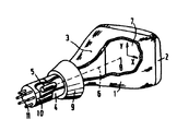
제1도는 투영 텔레비젼 표시관의 부분적 절개 입면도.1 is a partial cutaway elevation of a projection television display.
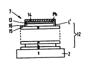
제2도는 표시 스크린, 필터 및 표시 원도우의 일부에 대한 단면도.2 is a cross-sectional view of a portion of a display screen, a filter and a display window.
제3도는 본 발명에 따른 표시관에서 사용되는 바와 같은 필터의 구성을 개략 도시하는 도면.3 is a diagram schematically showing the configuration of a filter as used in a display tube according to the present invention.
제4도는 LaOCl : Tb의 스펙트럼도.4 is a spectral diagram of LaOCl: Tb.
제5도는 본 발명에 따른 표시관에 대하여, 제3도에서 도시된 필터를 통한 광선의 법선에 대한 각 α와 투과 T와의 함수도.FIG. 5 is a function diagram of the angle α and transmission T for the normal of the light beam through the filter shown in FIG. 3, for a display tube according to the invention.
제6도는 제3도에 도시된 필터에 대하여 스펙트럼의 수직 입사 광선(0o)에 대한, 파장 λs와 투과 T와의 함수도.FIG. 6 is a function plot of wavelength λ s and transmission T for the normal incident light ray (0 o ) of the spectrum with respect to the filter shown in FIG.
제7도는 투영 텔레비젼 표시관상에서 측정한 각 α와, 방출광 d∮/dα의 각도 분포도와의 함수도.7 is a function diagram of angle α measured on a projection television display tube and an angle distribution diagram of emitted light d∮ / dα.
제8도는 14층 필터와 20층 필터에 대한 각 α와 투과 T와의 함수도.8 is a function diagram of angle α and transmission T for 14-layer and 20-layer filters.
* 도면의 주요부분에 대한 부호의 설명* Explanation of symbols for main parts of the drawings
1 : 유리봉합체(glas envelope) 2 : 표시 윈도우1: glass envelope 2: display window
5 : 전자총 6 : 전자 빔5: electron gun 6: electron beam
7 : 표시 스크린 9 : 편향 코일7: display screen 9: deflection coil
12 : 다층 간섭 필터(multilayer interference filter)12: multilayer interference filter
14 : 알루미늄막14: aluminum film
본 발명은 표시관에 관한 것으로서, 공동 봉합체(evacuated envelope)내에서 상기 봉합체의 벽내의 표시윈도우(display window)내측에 제공된 발광 물질의 표시 스크린과, 상기 발광 물질 및 표시 윈도우 사이에 설치되어 고 굴절률의 물질 및 저 굴절률의 물질을 교대로 설치하여 다수의 층으로 제조된 다층 간섭 필터(multilayer interference filter)를 구비하고 있는 표시관에 관한 것이다.BACKGROUND OF THE
표시관의 응용분야는 상당히 넓다. 예를들어, 투영 텔레비젼 표시관, 오실로스코프관, X선 증폭관, 데이타 그래픽 표시관 혹은 텔레비젼 표시관등에서 이용되고 있다.The field of application of the display tube is quite wide. For example, it is used in a projection television display tube, an oscilloscope tube, an X-ray amplifier tube, a data graphic display tube, or a television display tube.
이러한 표시관은 이미 공개된 독일 특허출원 제2330898호로 부터 공지되어 있는데, 상기 출원에서는 다층간섭 필터가 발광물질(인)과 표시 윈도우 사이에 사용되고 있다. 고 굴절률의 물질을 갖고 있는 필터층의 경우에 있어서, 각층의 광학 두께는 0.25λ 이하이거나 혹은 0.5λ 내지 0.75λ 사이에 있도록 선택되며, 여기서 λ는 발광 물질에 의해 방출된 광의 파장이다. 광학 두께가 0.25이거나 또는 그것의 기수배인 것은 저굴절률의 물질의 필터층에 사용된다. 관의 표시 스크린의 광 반사 특성은 필터에 따라 변화하는데, 한정된 각도의 애퍼튜어내에서 반사된 광량이 필터가 없는 관에 비해 25% 증가한다. 동시에 형성된 화상의 콘트라스트는 배경 광도(background brightness)가 감소함에 따라 증가한다.Such a display tube is known from the already published German patent application No. 2330898, in which a multi-layer interference filter is used between the phosphor (phosphorus) and the display window. In the case of a filter layer having a high refractive index material, the optical thickness of each layer is selected to be equal to or less than 0.25λ or between 0.5λ and 0.75λ, where λ is the wavelength of light emitted by the luminescent material. Optical thicknesses of 0.25 or even multiples thereof are used for filter layers of low refractive index materials. The light reflection characteristic of the tube's display screen varies with the filter, with a 25% increase in the amount of light reflected within the finite angle aperture compared to the tube without the filter. The contrast of the simultaneously formed image increases as the background brightness decreases.
이와 유사한 표시관이 영국 특허 제1,306,335호에 설명되어 있는데, 여기에서는 소위 통과 대역 간섭 필터(pass-band interference filter)가 발광 물질과 표시 스크린 사이에 사용되고 있다. 이 필터는 0.25λ의 광학 두께층을 가지며 다음과 같은 구성으로 되어 있다. 즉,A similar display tube is described in British Patent No. 1,306,335, where a so-called pass-band interference filter is used between the luminescent material and the display screen. This filter has an optical thickness layer of 0.25 lambda and has the following configuration. In other words,
![]()
![]()
여기서 S는 표시 스크린이고, L은 저 굴절률의 물질층이며, H는 고 굴절률의 물질층이다. 또한 이러한 필터의 구성은 다음과 같이 쓸 수도 있다.Where S is a display screen, L is a low refractive index material layer, and H is a high refractive index material layer. In addition, the configuration of such a filter can be written as follows.
![]()
![]()
파브리-페로(Fabry-Perot) 필터는 서로 반대로 설치되어 저 굴절률(L)6을 갖는 6층으로 형성된다. 광학층 두께의 수정의 선택에 있어서, 상기 필터는 수직에 대해 25o내지 40o이하의 각을 이루는 광선에 대하여 소망의 투과대역을 갖는다. 그러나 수직에 대해 55o내지 90o사이의 각을 포함하는 광선에 대해서는 바람직하지 못한 투과 대역을 갖게된다. 이러한 대역을 통과하는 모든 광은 소멸되거나, 소위 후광(halo)으로 분포할 뿐이며, 이결과, 표시된 화면에 있어서의 콘트라스트를 저해한다. 이에 대해서는 후술하겠다. 더군다나 이 필터에서 사용되는 방정석 층(cryolite layer)은 습기가 차기 쉽고 부드러워, 필터가 쉽게 손상될 수 있다. 이 필터에 사용되는 아연 황화물 층은 관이 약 460o의 온도로 가열되었을 때 쉽게 산화되므로, 이들을 표시관에 사용하기에는 부적당하다.Fabry-Perot filters are installed opposite each other to form six layers having a low refractive index (L) 6 . In the selection of a modification of the optical layer thickness, said filter has a desired transmission band for light rays with respect to an angle of 25 o to 40 o or less with respect to the vertical. However, with respect to the vertical for a light beam including an angle between 55 o to 90 o it will have a transmission band undesirable. All light passing through these bands is either extinguished or distributed only as a so-called halo, as a result of which the contrast on the displayed screen is inhibited. This will be described later. Furthermore, the cryolite layer used in this filter is easy to moisten and soft, which can easily damage the filter. The zinc sulfide layer used in this filter is easily oxidized when the tube is heated to a temperature of about 460 ° , making them unsuitable for use in display tubes.
J.D.Rancourt가 SID의 잡지 25권의 "음극 선관의 표면판에 대한 반 후광 코팅(anti-halo coating)" 논문에서 후광 효과를 억제하는 11층 엣지(edge) 필터와 8층 통과대역 간섭 필터를 발표했다. 상기 내용은 상기 필터들중의 하나를 투영 T.V(상기 책 47면 상단 오른쪽)를 위하여 사용하도록 설명되어 있다. 그러나 투영 T.V를 위한 11층 필터는 상당량의 빛이 넓은 각도로 통과하기 때문에 많은 손실을 가져온다.JDRancourt announces 11-layer edge filters and 8-layer passband interference filters to suppress halo effect in SID's 25 issue of "anti-halo coating of surface plates of cathode ray tubes." did. The above description is made to use one of the filters for the projection T.V (upper right of page 47 of the book). However, the eleven-layer filter for projection T.V introduces a lot of loss because a large amount of light passes through a wide angle.
그러므로 본 발명의 목적은 다층 간섭 필터 표시관을 제공하는데 있는 것으로 있는데, 이 필터는 수직에 대해 25o내지 40o의 각도 애퍼튜어내에 관에서 만들어지는 총 광량이 필터없는 유사관과 비교해서 볼때, 중심 파장이 적어도 40% 내지 50% 더 크게 된다.It is therefore an object of the present invention to provide a multi-layer interference filter indicator which, in comparison with a filterless pseudotube, the total amount of light produced in the tube within an angle aperture of 25 o to 40 o with respect to the vertical. The center wavelength is at least 40% to 50% larger.
본 발명의 다른 목적은 필터의 수직에 대해 약 35o내지 90o사이의 각도를 이루는 광선이 제2투과 대역에서 발생되지 않도록 다층 간섭 필터를 선택하는데에 있다.Another object of the present invention to a light beam that forms an angle of between about 35 o to 90 o to select the multi-layer interference filter from being generated in the second transmission band of the filter with respect to the vertical.
본 발명의 또다른 목적은 이미 공지된 관과 비교해 볼때, 표시된 화상의 색채 향상과 더 나은 콘트라스트가 가능하도록 다층 간섭 필터 표시관을 만드는데 있다.Another object of the present invention is to make a multi-layer interference filter tube in order to enable better color contrast and better contrast of the displayed image as compared to tubes already known.
본 발명의 마지막 목적은 440℃ 내지 460℃에서 소성될 수 있는 다층 간섭 필터 표시관을 만드는데 있다.The last object of the present invention is to make a multilayer interference filter tube which can be fired at 440 ° C to 460 ° C.
본 발명에 의하면, 서두에서 설명됐던 종류의 표시관은 실질적으로 필터가 14층 내지 30층, 더욱 양호하게는 18층 내지 22층으로 구성되는 것을 특징으로 하며, 각기 nd의 광학 두께를 가지고 있다(n)은 층을 이루고 있는 물질의 굴절률이고, (d)는 그 두께이다). 상기 광학 두께 nd는 0.2λf와 0.3λf사 사이의 값을 가지고 있으며, 더 정확히 말해서 0.23λf와 0.27λf사이의 값을 가지고 있다(λf는 P×λ와 동등하고, λ는 발광 물질에 의해 방출된 스펙트럼에서 선택된 중심파장이고, P는 1.18과 1.36 사이의 한 수치이다). 평균 광학두께는 0.25λf이고, λf는 필터의 중심 파장이다. 주파수 스케일상에서 λf(혹은 1/λf)는 수직 입사광선에 대한 반사 대역의 중심파장을 나타낸다. 가장 외부층의 필터는 고 굴절 물질로 제조된다.According to the present invention, the display tube of the type described at the outset is characterized in that the filter substantially consists of 14 to 30 layers, more preferably 18 to 22 layers, each having an optical thickness of nd ( n) is the refractive index of the layered material, and (d) is its thickness). The optical thickness nd has a value between 0.2λ f and 0.3λ f yarns, more precisely, has a value between 0.23λ f and 0.27λ f (λ f is equal to P × λ, and λ is light emission. The central wavelength chosen from the spectrum emitted by the material, and P is a number between 1.18 and 1.36). The average optical thickness is 0.25λ f, f λ is the central wavelength of the filter. Λ f (or 1 / λ f ) on the frequency scale represents the center wavelength of the reflection band for vertical incident light. The outermost filter is made of a high refractive material.
그러므로 필터는 대체로 약 0.25λf와 광학 두께를 가진 층으로 구성된다. 상기 필터의 수직에 대한 대략 35o내지 90o사이의 각을 이루는 광선에 대한 넓은 반사 대역(투과는 없다)을 갖는 특별한 특성을 가지고 있다.Therefore, the filter is generally composed of a layer having about 0.25λ f and an optical thickness. It has a special characteristic with a wide reflection band (no transmission) for light rays that form an angle between approximately 35 ° and 90 ° with respect to the vertical of the filter.
예를들어, 0.75λf와 1.25λf의 필터에서 반사 대역의 넓이는 각각 계수 3 및 5에 의해 감소되며, 원치않는 투과가 큰 각도로 발생한다. 상기 결과에 따라, 상기 필터에 진행 방향에서 발광효율의 이득은, 예를들어 독일 특허출원 제2,330,898호에서 같이, 필터의 수직면과 작은 각도를 만드는 광선에 대한 이득을 나타내는데, 이는 25%로 제한된다. 상기 또한 콘트라스트에 있어서도 작은 이득을 가져온다. 영국 특허출원 제1,306,335호에 따른 파블리-페로 필터는 세개의 1.5λ 층으로 구성되며(각 층은 저 굴절률의 물질로된 6개의 0.25λ 층으로 구성된다), 또한 필터의 수직에 대해 큰 각도를 이루는 광선에 대한 바람직하지 못하게 넓은 투과 대역을 가지고 있다.For example, in the filters of 0.75λ f and 1.25λ f the area of the reflection band is reduced by coefficients 3 and 5, respectively, and unwanted transmission occurs at large angles. As a result of this, the gain of luminous efficiency in the advancing direction of the filter is indicative of a gain for light rays which make a small angle with the vertical plane of the filter, for example in German Patent Application No. 2,330,898, which is limited to 25%. . This also brings about a small gain in contrast. The Fably-Perot filter according to British Patent Application No. 1,306,335 consists of three 1.5λ layers (each layer consisting of six 0.25λ layers of low refractive index material) and also has a large angle to the vertical of the filter. It has an undesirably wide transmission band for the rays that make up.
이미 상기했던 것처럼, 후광 억제(halo suppression)용 필터는 1984년에 간행된 SID의 잡지 25/1권의 상기 논문에서 설명되었다. 필터의 주 목적이 무엇보다도 먼저 진행 방향으로의 발광 효율을 향상시키는 것만은 아니다라고 설명되어 있다. 균일한 흡수력을 가진 필터가 사용된다. 소수의 층 때문에, 상기 필터는 반사가 현저히 감소하는 각도(허용각도)와 같이 다소 임계적이다. 상기 본 발명의 특징은 필터의 엣지(edge)위치가 정확히 한정되고(λf=Pλ에서 P와 λf때문에), 허용 각도는 비교적 작다는 것이다. 이 결과에서와 같이, 필터는 큰 각도에서의 손실에 매우 민감하고, 많은층(14 내지 30층)을 가진 필터가 요구되고 있다.As already mentioned above, a filter for halo suppression is described in the above paper in SID magazine 25/1, published in 1984. It is explained that the main purpose of the filter is not only to first improve the luminous efficiency in the advancing direction. Filters with uniform absorption are used. Because of the few layers, the filter is somewhat critical, such as the angle at which the reflection is significantly reduced (permissible). A feature of the present invention is that the edge position of the filter is exactly defined (because of P and λ f at λ f = Pλ) and the permissible angle is relatively small. As in this result, the filter is very sensitive to loss at large angles, and a filter having many layers (14 to 30 layers) is required.
본 발명에 따라 필터층 두께는 원하는 파장에서 반사가 발광 물질로부터의 광선이 많이 증가하도록 선택되어지는데, 광선의 각도는 필터의 수직면에서 20o내지 35o의 큰 각도를 이룬다. 넓은 반사 대역으로 인해 25o내지 40o보다 큰 각도를 가진 광선은 가능한한 많이 방사되고, 다시 발광 물질에서의 산란(scattering)후에 필터의 수직에 대하여 25o내지 40o의 각 이내의 관으로부터 방사할 기회를 갖게 된다. 이 결과로 진행 방향과 작은 각도에서, 최대 발광 효율이 얻어지며, 인(phosphor)의 중심 파장 λ는 필터를 사용안할때보다 약 40% 더 크다. 더군다나, 넓은 반사 대역은 크게 감소한 후광 효과를 나타냈고, 큰 각도에서 방출된 광선이 더 적다는 것을 입증하였다. 필터층의 광학 두께 nd는 모든 층이 같은 것이 아니라 구체적인것에 관한 보다 상세히 설명한 것처럼 0.2λf와 0.3λf, 오히려 더 0.23λf와 0.27λf사이에서 변한다. 이러한 두께의 변화의 결과로, 필터의 평탄한 응답 곡선을 얻는다. 필터의 응답 곡선이 파장에 종속하기 때문에 인과 채용된 필터의 결합에 의해서 필터상에서 수직에 대하여 25o내지 40o각도 이내로 필터를 통과하여 지나는 광선의 색채점을 향상시키는 것이 가능하다.According to the invention the filter layer thickness is chosen such that the reflection at the desired wavelength increases the light rays from the luminescent material much, the angle of the light rays being from 20 o to 35 o in the vertical plane of the filter. Due to the broad reflection band, light rays with angles greater than 25 o to 40 o are emitted as much as possible, again from a tube within an angle of 25 o to 40 o with respect to the vertical of the filter after scattering in the luminescent material You have a chance to do it. As a result, at a small angle with the direction of travel, the maximum luminous efficiency is obtained, and the center wavelength? Of the phosphor is about 40% larger than without the filter. Furthermore, the broad reflection band showed a significantly reduced halo effect, demonstrating fewer rays emitted at larger angles. The optical thickness nd of the filter is varied as if all layers are described in detail than relates not to the same concrete between 0.2λ f and 0.3λ f, rather 0.23λ f and 0.27λ f. As a result of this change in thickness, a flat response curve of the filter is obtained. Since the response curve of the filter is wavelength dependent, it is possible to improve the color point of the light passing through the filter within an angle of 25 o to 40 o with respect to the vertical on the filter by the combination of the causal filter.
P의 값은 1.18과 1.36 사이에 있는데, 이는 사용되고 있는 층 굴절률과 선택된 파장범위에 의존한다. 이는 특별한 예에 대하여 설명될 것이다. TiO2-SiO2필터에서, P=λf/λ는 1.22와 1.36 사이에 값이 있다.The value of P is between 1.18 and 1.36, depending on the layer refractive index being used and the wavelength range chosen. This will be explained with respect to a particular example. In TiO 2 -SiO 2 filters, P = λ f / λ has a value between 1.22 and 1.36.
본 발명에 의한 표시관의 제1의 양호한 실시예는 발광 물질이 테르븀(terbium) 활성화된 실질적으로 녹색으로 발광하는 인으로 구성됐는데, λ=545nm이고, P는 TiO2-SiO2필터에서 1.22와 1.27 사이에서의 수치이다. 테르븀 활성화된 실질적으로 녹색으로 발광하는 인은 예를들어 이트륨 알루미늄 석류석-테르븀(YAG : Tb), 이트륨 규산염 -테르븀(Y2SiO5: Tb), 란탄 산화브롬-테르븀(LaOBriTb), 란탄옥시크로라이드-테르븀(Laoc1 : Tb), 그리고 인듐 붕산염-테르븀 등이 있다. 모든 이런 Tb-활성화된 녹색인의 중심 파장은 545nm이다.A first preferred embodiment of the display tube according to the invention consists of phosphorus which the luminescent material emits terbium-activated substantially green, with λ = 545 nm, where P is equal to 1.22 in the TiO 2 -SiO 2 filter. This is a number between 1.27. Phosphorus that emits terbium-activated substantially green light is, for example, yttrium aluminum garnet-terbium (YAG: Tb), yttrium silicate-terbium (Y 2 SiO 5 : Tb), lanthanum bromine oxide-terbium (LaOBriTb), lanthanumoxychrome Ride-terbium (Laoc1: Tb), and indium borate-terbium. The central wavelength of all these Tb-activated green phosphorus is 545 nm.
본 발명에 따라서 P값이 1.22 내지 1.27이고 값이 660 내지 690nm인 필터를 선택할 때, 이 필터는 필터의 수직에 대하여 25o내지 35o보다 더 작은 각도를 갖는 광선에 대해 고투과(90%이상)를 얻는다. 필터의 수직에 대한 25o내지 40o보다 더 큰 각도를 갖는 광선에서, 투과는 급속도로 감소하고 반사가 90o이상에서 생긴다. 이 필터는 청색, 녹색, 주황색, 적색의 방출선을 갖는 이러한 Tb-활성화된 인과 함께 특히 잘 작용한다. 필터를 사용함으로써 이득이 녹색에서 일어나고, 더 작은 이득이 청색에서 일어나며, 관에서 방사된 광량의 실질적인 완전 감소가 적색에서 일어나는데, 이득은 색채점들을 선호한다. 이런 모든 것들은 발광 효율과 색채 향상(EBU 표준에 가까운)을 제공하며 콘트라스트에서 이득을 제공한다. 이런 Tb-활성화된 인을 가진 최적 조건의 필터에서, 모든 색채의 발광 효율의 총 이득은 30% 내지 60%이다. 녹색의 이득은 50% 내지 100%이다. CIE색 삼각형에서 X좌표와 Y좌표는 각각 0.26 내지 0.30, 0.60 내지 0.64이다. 필터를 사용치 않았을 때 이들 좌표는 각각 X=0.33 내지 0.36, Y=0.54 내지 0.59이다. 콘트라스트에서의 이득은 약 2이다. 투영 텔레비젼 경우에서처럼 렌즈를 가진 광학 표시에서, 이것은 중요한 잇점, 즉 더 작은 색채 수차(chromatic aberration)를 나타낸다.(적색이 거의없고, 녹색을 청색과 서로 맞대어 비례적으로 더 적어진다)According to the invention, when selecting a filter with a P value of 1.22 to 1.27 and a value of 660 to 690 nm, the filter is highly transmissive (90% or more) for light rays having an angle smaller than 25 o to 35 o with respect to the vertical of the filter. Get In light rays having an angle greater than 25 o to 40 o with respect to the vertical of the filter, transmission rapidly decreases and reflection occurs above 90 o . This filter works especially well with these Tb-activated phosphorus with blue, green, orange and red emission lines. By using a filter, the gain occurs in green, a smaller gain occurs in blue, and a substantial complete reduction in the amount of light emitted from the tube occurs in red, which favors color points. All of these provide luminous efficiency and color enhancement (close to the EBU standard) and gain in contrast. In an optimal filter with such Tb-activated phosphorus, the total gain of luminous efficiency of all colors is from 30% to 60%. The gain of green is 50% to 100%. In the CIE color triangle, the X and Y coordinates are 0.26 to 0.30 and 0.60 to 0.64, respectively. Without a filter, these coordinates are X = 0.33 to 0.36 and Y = 0.54 to 0.59, respectively. The gain in contrast is about two. In optical displays with lenses, as in the projection television case, this represents an important advantage: smaller chromatic aberration (almost no red, proportionally less green against blue).
본 발명에 따른 표시관의 두번째 양호한 실시예는 발광 물질이 λ=490nm인 테르븀-활성화된 청색-발광인과 P가 TiO2-SiO2필터에서 l.22 내지 1.27의 값을 가지고 있는 점을 특징으로 한다. 도핑을 위한 약간의 Tb를 사용함으로써, λ=490nm를 가진 주된 청색 발광인을 얻을 수 있다. 1.22 내지 1.27 사이에서 P를 선택함으로써, λf는 595nm 내지 620nm 사이에 있게되며, 필터의 수직에 대한 25 내지 40o이상의 각도를 이루는 광선의 반사가 비교적 급속도로 증가하는 필터가 얻어진다. 그 다음에 70% 내지 100%의 콘트라스트 이득을 얻을 수 있고, 청색에서의 발광 효율의 이득은 50% 내지 90%이다. 녹색의 스펙트럼선이 다층 필터에 의해 여파되기 때문에 현저한 색채점 향상을 가져온다.A second preferred embodiment of a display tube according to the invention is characterized in that the terbium-activated blue-emitting phosphor having a λ = 490 nm and P has a value of l.22 to 1.27 in the TiO 2 -SiO 2 filter. It is done. By using some Tb for doping, it is possible to obtain the main blue luminescent phosphor with λ = 490 nm. By selecting P between 1.22 and 1.27, [lambda] f is between 595 nm and 620 nm, and a filter is obtained in which the reflection of light rays at an angle of 25 to 40 o or more with respect to the vertical of the filter increases relatively rapidly. A contrast gain of 70% to 100% can then be obtained, and the gain of luminous efficiency in blue is from 50% to 90%. The green spectral lines are filtered out by the multilayer filter, resulting in a significant improvement in color score.
본 발명에 따른 표시관의 세번째 양호한 실시예는 발광물질이 유로퓸-활성화된 이트륨 산화물(Y2O3: Eu)이고, λ=612nm이며, P값은 TiO2와 SiO2필터에서 1.22 내지 1.27 사이에 있다는 것에 특징이 있다. P값을 1.22 내지 1.27 사이에 잡고 λf값을 745nm 내지 780nm 사이에 잡은 이러한 선택의 결과에 따라서, 필터의 수직에 대하여 25o내지 40o이상의 각도를 이루는 광선에 대한 필터 반사는 상당히 증가한다. 전체 발광 효율에서 60% 내지 l00%의 이득이 있게 된다. 콘트라스트의 이득은 약 100%이다. 이 경우에는 약간의 색채점 향상이 있다. 생성된 광의 스펙트럼에서 적색 성분은 더 짧은 파장 성분보다 실제적으로 강해진다.A third preferred embodiment of the display tube according to the invention is that the luminescent material is europium-activated yttrium oxide (Y 2 O 3 : Eu), λ = 612 nm, and the P value is between 1.22 and 1.27 in TiO 2 and SiO 2 filters. It is characterized by being in. Holding the P value between 1.22 to 1.27 depending on the result of this selection caught between 745nm to 780nm to λ f value, the filter reflection for light rays constituting an angle more than 25 o to 40 o with respect to the vertical of the filter is significantly increased. There is a gain of 60% to l00% in the overall luminous efficiency. The gain of contrast is about 100%. In this case, there is a slight improvement in color score. The red component in the spectrum of generated light is actually stronger than the shorter wavelength component.
본 발명은 넓은 대역의 인에서 사용될 수 있는데, 예를들어 윌레마이트(Zn2SiO4: Mn), 아연 황화물-은(ZnS : Ag), 스트론튬 알루민산염-유로퓸(SrA13O8.5: Eu)는 각기 중심 파장 λ가 530nm, 460nm, 460nm이다. P값은 1.25 내지 1.36에서 얻어진다.The present invention can be used in a wide range of phosphorus, for example, willemite (Zn 2 SiO 4 : Mn), zinc sulfide-silver (ZnS: Ag), strontium aluminate- europium (SrA1 3 O 8.5 : Eu) Are the center wavelengths λ, respectively, 530 nm, 460 nm, and 460 nm. P values are obtained from 1.25 to 1.36.
모든 실시예에 있어서 고 굴절률을 가진 필터층은 티타늄 산화물(TiO2)이나 탄탈 산화물(Ta2O5)로 이루어져 있다. 저 굴절률 층은 실리콘 이산화물(SiO2)나 마그네슘 불화물(MgF2)로 이루어져 있다. 이러한 층들은 기상증착(vapour deposition) 이나 스퍼터링(sputtering)에 의해서 이루어진다. MgF2에 대한 기상증착은 충분히 단단한 층을 얻기 위해서 약 300o의 온도에서 실행되어야 한다. Ta2O5-SiO2의 최적 P값은 TiO2-SiO2필터보다 낮은 약 0.04 내지 0.05이다. 이때 반사 대역은 덜 넓어지게 된다.In all embodiments, the filter layer having a high refractive index is made of titanium oxide (TiO 2 ) or tantalum oxide (Ta 2 O 5 ). The low refractive index layer consists of silicon dioxide (SiO 2 ) or magnesium fluoride (MgF 2 ). These layers are made by vapor deposition or sputtering. Vapor deposition on MgF 2 should be carried out at a temperature of about 300 o to obtain a sufficiently rigid layer. The optimum P value of Ta 2 O 5 —SiO 2 is about 0.04 to 0.05, lower than that of the TiO 2 —SiO 2 filter. The reflection band then becomes less wide.
본 발명에 따른 표시관의 네번째 양호한 실시예는 발광 물질을 향하는 필터 가장 바깥의 약 0.25λf두께층은 고 굴절률의 물질로 이루어져 있고, 저 굴절률의 물질의 광학 두께가 약 0.125λf인 종단층으로 덮혀있는데, 그 종단층상에는 발광물질이 제공된다.In a fourth preferred embodiment of a display tube according to the invention, the outermost layer of about 0.25λ f thickness towards the luminescent material consists of a material of high refractive index, and the termination layer has an optical thickness of about 0.125λ f of low refractive index material. Covered with a light emitting material on the termination layer.
본 발명에 따른 표시관의 다섯번째 양호한 실시예는, 표시 윈도우를 향하는 가장 바깥의 약 0.25λf두께층은 고 굴절률의 물질로 이루어져 있고, 저 굴절률의 물질의 약 0.125λf의 광학 두께로 된 중간층으로 코팅되어 있다. 각기 인측(phosphor side)과 혹은 표시 윈도우 측에서 약 0.125λf의 광학 두께를 가진 종단층과 혹은 중간층을 제공함으로써, 수직에 비해 작은 각도 차이로 둘러쌓인 광선의 진행 방향에서 투과는 증가되고, 투과시 진동은 감소된다. 반응 곡선은 더 평탄하게 된다.In a fifth preferred embodiment of a display tube according to the invention, the outermost about 0.25 lambda f thick layer facing the display window consists of a material of high refractive index and has an optical thickness of about 0.125 lambda f of a low refractive index material. It is coated with an intermediate layer. By providing a termination layer and an intermediate layer having an optical thickness of about 0.125λ f at the phosphor side and the display window side, the transmission is increased in the direction of propagation of the light rays surrounded by a small angle difference compared to the vertical, and the transmission Time vibration is reduced. The response curve is flatter.
본 발명에 따른 표시관의 여섯번째 양호한 실시예는 발광 물질을 향하는 가장 바깥의 약 0.25λf두께의 필터층은 금속 산화물의 혼합물로 이루어져 있다. 혼합물은 티타늄 산화물(TiO2), 베릴륨 족 산화물(BeO)로부터 생성된 금속 산화물, 마그네슘 산화물(MgO), 칼슘 산화물(CaO)로 구성되고, 티타늄 산화물의 특성은 상기 물질들의 혼합물의 무게에 비해서 70% 내지 99%이다.In a sixth preferred embodiment of the display tube according to the invention, the outermost about 0.25λ f thick filter layer facing the luminescent material consists of a mixture of metal oxides. The mixture consists of titanium oxide (TiO 2 ), metal oxide produced from beryllium group oxide (BeO), magnesium oxide (MgO), calcium oxide (CaO), and the characteristics of titanium oxide are 70% by weight of the mixture of the above materials. % To 99%.
이러한 부가의 평면을 사용함으로써, 필터의 인이 있는 측상의 구멍이 많은 코팅 층은 적어지므로, 인의 광학 접촉은 감소되어 콘트라스트에서 이득과 효율은 급속히 증가된다.By using this additional plane, the less perforated coating layer on the phosphorus side of the filter is reduced, so that the optical contact of the phosphorus is reduced and the gain and efficiency in contrast are rapidly increased.
본 발명에 의한 관은 광학적으로 렌즈 시스템과 연결되는데 바람직하게는 액체를 통해 광학적으로 연결되거나 외측상의 코팅 유리가 비반사층으로 되어 있는 냉각 액체가 제공된다. 표시 윈도우가 대체로 평면 윈도우로 사용됨에 따라 일반적으로 투영 텔레비젼 표시 윈도우로 사용된다.The tube according to the invention is optically connected with the lens system, preferably provided with a cooling liquid which is optically connected via a liquid or in which the coated glass on the outside is an antireflective layer. As display windows are generally used as flat windows, they are generally used as projection television display windows.
표시관은, 본 발명에 조합될 수 있다고 사료되는 미합중국 특허출원 제226,589호의 유리섬유 광학의 윈도우로 사용될 수 있다.The display tube may be used as a window of glass fiber optics of US Patent Application No. 226,589, which is considered to be incorporated in the present invention.
본 발명의 표시관은 투영 텔레비젼 방식에 효과적으로 사용될 수 있다. 진행 방향으로 방사된 매우 밝은 영상은 예를들어 25o내지 30o의 제한 허용각도를 갖는 렌즈 시스템에 의해 손실없이 얻어진다. 이러한 결과로 더 뚜렷한 콘트라스트를 갖는 밝은 화상과 향상된 색채 연출을 얻게 된다.The display tube of the present invention can be effectively used for the projection television system. Very bright images radiated in the advancing direction are obtained without loss by, for example, a lens system with a limited tolerance angle of 25 ° to 30 ° . The result is a bright image with more pronounced contrast and improved color reproduction.
이하 첨부도면을 참조하면서, 본 발명을 더욱 상세히 설명하기로 한다.Hereinafter, the present invention will be described in more detail with reference to the accompanying drawings.
제1도는 부분적으로 절단된 본 발명의 투영 텔레비젼 표시관의 투시도이다. 유리 봉합체(l)에 구성된 것을 보면 표시 윈도우(2)와 원추체(3)와 넥(neck)(4)으로 되어 있는데, 상기 넥에서 전자총(5)은 전자 빔(6)을 발생시킨다. 상기 전자 빔(6)은 표시 스크린(7)에 하나의 점(8)이 형성되도록 집속시킨다. 표시 스크린(7)은 표시 윈도우(2) 내측에 제공된다. 전자 빔은 편향코일(9)에 의하여 두개의 서로 수직방향 좌표 X,Y에서 표시 스크린(7)상으로 편향된다. 관은 연결핀(11)을 가진 캡(10)을 포함한다.1 is a perspective view of a partially cut out projection television display of the present invention. As shown in the glass encapsulation l, it consists of a display window 2, a cone 3 and a neck 4, in which an electron gun 5 generates an
제2도는 표시 윈도우(2)와 다층 간섭 필터(12)와 표시 스크린(7)의 일부분을 도시한 도면이다. 다시 표시 스크린은 발광물질(인)층과 얇은 알루미늄 막(14)(소위 "알루미늄 베이킹(aluminium backing))"으로 구성된다.2 shows a portion of the display window 2, the
제3도는 표시 스크린(7) 사이의 20층 필터를 도시적으로 표시한 것인데, 이는 인(13)(Ph)층과 알루미늄막(14), 표시 윈도우(2)(S)로 구성된다. 필터는 절차 L로 표시된 SiO2층(굴절률 n=1.47)과 TiO2층과 H로 표시된 TiO2층(n=2.35)으로 구성되어 있다. 층들은 약 0.25λf의 두께를 가지고 있다. 표시 스크린 위에서 맨 마지막의 약 0.25 두께의 층(15)은 약 0.125λf두께의 종단층(16)(L')으로 코팅된다.FIG. 3 shows a 20-layer filter between the display screens 7 in an illustration, which is composed of a phosphorus 13 (Ph) layer, an
인(13)은 =545nm의 Tb-인이다. P=1.25에서 λf는 680nm이다. 이러한 λf에서 필터 구성은 다음표에 기록되어 있다.

제4도는 란타늄 옥시크로라이드-테르븀의 스펙트럼(λs의 함수로서 %의 가장 높은 첨두치(Ip)을 표준화한 명암도)을 보여준다. 이런 스펙트럼은 모든 녹색 테르븀인의 표본이다. 예를들어 이트륨 알루미늄석류석-테르븀(YAG : Tb), 이트륨 규산염-테르븀(Y2SiO5: Tb), 란탄 옥시브로마이드-테르븀(LaOBr : Tb)와 인듐 붕산염-테르븀(InBo3: Tb)이다.4 shows the spectrum of lanthanum oxychromide-terbium (contrast normalizing the highest peak (Ip) of% as a function of λ s ). This spectrum is a sample of all green terbium phosphorus. For example, yttrium aluminum garnet-terbium (YAG: Tb), yttrium silicate-terbium (Y 2 SiO 5 : Tb), lanthanum oxybromide-terbium (LaOBr: Tb) and indium borate-terbium (InBo 3 : Tb).
제5도는 λ=545nm인 필터의 수직에 대하여 각 α의 함수로서 제3도에서 보여준 필터의 투과 T(실선)을 나타낸다. α50%는 필터의 투과에서 50% 감소되는 것을 나타내는데, 이의 각도는 약 32o이다. 비교해볼때 이 도면은 상기 영국 특허출원 제1,306,335호에 의한 파브리-페로 필터에 대한 각 α의 함수로서 투과(점선)를 나타낸다. 본 발명에서 보여준 필터와 이러한 필터를 비교하기 위하여 이 필터의 α50%는 32o로 선택되어 왔다. 더구나, 그 물질은 같은 것, 즉 TiO2와 SiO2으로 선택되어 왔다. 그 필터의 다른 특성때문에, 이 경우에 있어서 P=1.02이고, λf=1.02×545=555nm이다. 이 필터의 큰 단점은 55o내지 90o사이의 넓은 투과 대역을 차지하고 있는 것이다. 이러한 투과 대역에서 투과된 모든 광은 손실되거나, 반사후에 후광으로 변질되거나 콘트라스트의 손실을 가져온다. 이러한 단점은 또한 0.75λf와 1.25λf필터에도 적용된다.5 shows the transmission T (solid line) of the filter shown in FIG. 3 as a function of angle α with respect to the vertical of the filter with λ = 545 nm. α50% represents a 50% reduction in the transmission of the filter, with an angle of about 32 ° . In comparison, this figure shows permeation (dashed lines) as a function of angle α for the Fabry-Perot filter according to British Patent Application No. 1,306,335. To compare this filter with the filter shown in the present invention, α50% of this filter has been selected as 32 o . Moreover, the material has been chosen to be the same, ie TiO 2 and SiO 2 . Due to the different characteristics of the filter, in this case P = 1.02 and lambda f = 1.02 × 545 = 555 nm. Main disadvantage of this filter is occupying the wide transmission band between 55 o to 90 o. All light transmitted in this transmission band is lost, deteriorates to halo after reflection or results in a loss of contrast. This disadvantage also applies to 0.75λ f and 1.25λ f filter.
제6도는 제3도 필터 분광 파장 λs의 함수로서 필터(0o)에 수직으로 입사하는 광선에 대한 투과 T를 나타낸다. 필터(단파 통과 필터)의 저역 통과 특성은 매우 뚜렷하며, 그래서 570nm 내지 815nm 사이의 넓은 반사 대역을 가지고 있다.6 shows the transmission T for light incident perpendicular to the
제7도는 제 3, 5, 6도에서 도시된 바와 같이 20층 필터 투영 텔레비젼 표시관에서 측정된 바와 같은 임의의 단위에서 각 d∮/dα의 함수로서 광속 ∮를 나타낸다. 32o보다 작은 각도에서는 필터없는(곡선 II) 투영텔레비젼 표시관에 대한 발광 효율(곡선 I)에서 확실한 이득이 있다.FIG. 7 shows the light flux 로서 as a function of each d∮ / dα in any unit as measured in a 20-layer filter projection television display as shown in FIGS. At angles smaller than 32 o there is a definite gain in luminous efficiency (curve I) for a filterless (curve II) projection television display tube.
제8도는 14층 필터(곡선 I)와 20층 필터(λ=612nm인 이트륨 산화물-유로퓸의 곡선 II)에 대한 각 α와 함수로서 투과 T를 나타낸다. 20층 필터는 λ만 제외하고는 제3도와 동일하되 P=1.25일때, λf=1.25×612=765nm이고 α50%=32o이다. 14층 필터는 P=1.25, λf=765, α50%=31o를 갖고, 다음과 같이 나타낸다.8 shows the transmission α as a function of angle α for the 14-layer filter (curve I) and the 20-layer filter (curve II of yttrium oxide-europium having lambda = 612 nm). The 20-layer filter is the same as FIG. 3 except for λ, but when P = 1.25, λ f = 1.25 × 612 = 765 nm and α50% = 32 o . The fourteen-layer filter has P = 1.25, lambda f = 765, and α50% = 31 o and is expressed as follows.

마지막으로 아래의 표는 다수의 다른 실시예와 그들의 결과가 주어졌다. 제1열은 표시 스크린에서 사용된 인의 종류를 나타낸다. 제2열은 상기 인의 중심파장을 나타내며, 제3열은 P의 작은 값을 나타낸다. 제4열은 투과 T=50%의 α값을 나타낸다. 제5열은 사용된 다수의 필터층을 나타낸다.Finally, the table below is given a number of different examples and their results. The first column shows the type of phosphorus used in the display screen. The second column shows the central wavelength of phosphorus and the third column shows the small value of P. The fourth column shows the α value of transmission T = 50%. The fifth column shows the number of filter layers used.


Claims (9)
Applications Claiming Priority (2)
| Application Number | Priority Date | Filing Date | Title |
|---|---|---|---|
| NL8402304A NL8402304A (en) | 1984-07-20 | 1984-07-20 | PICTURE TUBE. |
| NL8402304 | 1984-07-20 |
Publications (2)
| Publication Number | Publication Date |
|---|---|
| KR860001461A KR860001461A (en) | 1986-02-26 |
| KR930002112B1 true KR930002112B1 (en) | 1993-03-26 |
Family
ID=19844246
Family Applications (1)
| Application Number | Title | Priority Date | Filing Date |
|---|---|---|---|
| KR1019850005115A KR930002112B1 (en) | 1984-07-20 | 1985-07-18 | Display tube |
Country Status (10)
| Country | Link |
|---|---|
| US (2) | US4634926A (en) |
| EP (1) | EP0170320B1 (en) |
| JP (1) | JPS6139349A (en) |
| KR (1) | KR930002112B1 (en) |
| AT (1) | ATE31230T1 (en) |
| CA (1) | CA1229123A (en) |
| DD (1) | DD236616A5 (en) |
| DE (1) | DE3561123D1 (en) |
| ES (2) | ES8701431A1 (en) |
| NL (1) | NL8402304A (en) |
Families Citing this family (54)
| Publication number | Priority date | Publication date | Assignee | Title |
|---|---|---|---|---|
| GB2176048B (en) * | 1985-05-29 | 1989-07-05 | Philips Nv | Projection television display tube and projection television device comprising at least one such tube |
| NL8502226A (en) * | 1985-08-12 | 1987-03-02 | Philips Nv | PROJECTION TELEVISION EQUIPMENT. |
| GB8608925D0 (en) * | 1986-04-11 | 1986-05-14 | Philips Nv | Projection television system |
| GB8612358D0 (en) * | 1986-05-21 | 1986-06-25 | Philips Nv | Cathode ray tube |
| GB8623822D0 (en) * | 1986-10-03 | 1986-11-05 | Philips Nv | Colour cathode ray tube |
| NL8602975A (en) * | 1986-11-24 | 1988-06-16 | Philips Nv | IMAGE PROJECTION SYSTEM. |
| USRE34131E (en) * | 1986-12-10 | 1992-11-24 | U.S. Philips Corporation | Display tube having improved brightness distribution |
| GB8629552D0 (en) * | 1986-12-10 | 1987-01-21 | Philips Nv | Television system & display tubes |
| US4822144A (en) * | 1986-12-24 | 1989-04-18 | U.S. Philips Corporation | Electro-optic color display including luminescent layer and interference filter |
| CA1274613A (en) * | 1986-12-24 | 1990-09-25 | Leendert Vriens | Projection device and associated display device |
| GB8707975D0 (en) * | 1987-04-03 | 1987-05-07 | Philips Nv | Colour cathode ray tube |
| ES2077562T3 (en) * | 1987-07-22 | 1995-12-01 | Philips Electronics Nv | OPTICAL INTERFERENCE FILTER. |
| JPH01195639A (en) * | 1988-01-29 | 1989-08-07 | Matsushita Electric Ind Co Ltd | Cathode-ray tube for projection |
| EP0332790B1 (en) * | 1988-03-18 | 1994-11-30 | Instruments S.A. | Improved diffraction grating and method of making |
| US5245474A (en) * | 1988-03-22 | 1993-09-14 | Compagnie Generale D'electricite | Electromagnetic filter device |
| US4937661A (en) * | 1988-07-11 | 1990-06-26 | North American Philips Corporation | Projection television display tube and device having band pass interference filter |
| JPH02109237A (en) * | 1988-10-18 | 1990-04-20 | Nippon Electric Glass Co Ltd | Cathode-ray tube for projection type television |
| FR2640425A1 (en) * | 1988-12-09 | 1990-06-15 | Malifaud Pierre | Process for the spectral selection of radiation and device for implementation, especially video image television projector |
| US4914511A (en) * | 1988-12-23 | 1990-04-03 | North American Philips Corporation | Projection color TV using CRTs having interference filters with different number of layers |
| NL8900070A (en) * | 1989-01-12 | 1990-08-01 | Philips Nv | Apparatus for injecting an interference filter for a projection television picture tube. |
| JPH0834596B2 (en) * | 1989-02-20 | 1996-03-29 | 三菱電機株式会社 | Projection television |
| JPH0734354B2 (en) * | 1989-05-19 | 1995-04-12 | 日本電気硝子株式会社 | Cathode ray tube for projection television |
| JPH0744688B2 (en) * | 1989-06-08 | 1995-05-15 | 三菱電機株式会社 | Projection-type television system |
| US5248518A (en) * | 1989-06-27 | 1993-09-28 | Mitsubishi Denki Kabushiki Kaisha | Projection cathode ray tube |
| US5138222A (en) * | 1989-06-27 | 1992-08-11 | Mitsubishi Denki Kabushiki Kaisha | Projection cathode ray tube having an interference filter |
| US5073451A (en) * | 1989-07-31 | 1991-12-17 | Central Glass Company, Limited | Heat insulating glass with dielectric multilayer coating |
| FR2650914A1 (en) * | 1989-08-11 | 1991-02-15 | Thomson Tubes Electroniques | HIGH EFFICIENCY CATHODOLUMINESCENT SCREEN FOR HIGH LUMINANCE CATHODE RAY TUBES |
| JPH03127436A (en) * | 1989-10-11 | 1991-05-30 | Mitsubishi Electric Corp | Projection-type television apparatus |
| JPH03133034A (en) * | 1989-10-16 | 1991-06-06 | Mitsubishi Electric Corp | Projection-type cathode-ray tube |
| JPH03138838A (en) * | 1989-10-24 | 1991-06-13 | Mitsubishi Electric Corp | Projection type cathode-ray tube |
| JPH03198492A (en) * | 1989-12-26 | 1991-08-29 | Mitsubishi Electric Corp | Projector type television unit |
| US5065071A (en) * | 1990-01-02 | 1991-11-12 | North American Philips Corporation | Monochrome CRT with interference filter having filter layer with reduced transmission and projection color TV incorporating same |
| US5135300A (en) * | 1990-02-01 | 1992-08-04 | Mitsubishi Denki Kabushiki Kaisha | Projection color display apparatus |
| JP2650458B2 (en) * | 1990-03-29 | 1997-09-03 | 三菱電機株式会社 | Projection type cathode ray tube |
| JP2512204B2 (en) * | 1990-05-09 | 1996-07-03 | 三菱電機株式会社 | Projection type cathode ray tube |
| JP2714995B2 (en) * | 1990-05-29 | 1998-02-16 | 三菱電機株式会社 | Projection type cathode ray tube |
| KR920003398A (en) * | 1990-07-27 | 1992-02-29 | 김정배 | Projection tube with interference filter |
| JPH081791B2 (en) * | 1990-08-20 | 1996-01-10 | 三菱電機株式会社 | Projection type cathode ray tube |
| US5243255A (en) * | 1990-10-24 | 1993-09-07 | Mitsubishi Denki Kabushiki Kaisha | Cathode-ray tube with low reflectivity film |
| KR950014541B1 (en) * | 1991-05-24 | 1995-12-05 | 미쯔비시덴끼 가부시끼가이샤 | Cpt having intermediate layer |
| EP0536833B1 (en) * | 1991-10-10 | 1997-01-15 | Koninklijke Philips Electronics N.V. | X-ray examination apparatus |
| US5569977A (en) * | 1994-03-08 | 1996-10-29 | Philips Electronics North America Corporation | Cathode ray tube with UV-reflective filter and UV-excitable phosphor |
| US6074789A (en) * | 1994-03-08 | 2000-06-13 | Philips Electronics N.A. Corp. | Method for producing phosphor screens, and color cathode ray tubes incorporating same |
| JP3539784B2 (en) * | 1995-03-06 | 2004-07-07 | セイコーインスツルメンツ株式会社 | Method and apparatus for receiving selective call signal |
| JPH08322006A (en) * | 1995-05-24 | 1996-12-03 | Mitsubishi Electric Corp | Projection type television device |
| US5813753A (en) * | 1997-05-27 | 1998-09-29 | Philips Electronics North America Corporation | UV/blue led-phosphor device with efficient conversion of UV/blues light to visible light |
| US5999321A (en) * | 1998-06-19 | 1999-12-07 | Philips Electronics North America Corporation | Dichroic filters with low nm per degree sensitivity |
| KR100310693B1 (en) * | 1999-03-31 | 2001-10-17 | 김순택 | CPT with laminated filter layer |
| US6841802B2 (en) | 2002-06-26 | 2005-01-11 | Oriol, Inc. | Thin film light emitting diode |
| US7235792B2 (en) | 2004-05-19 | 2007-06-26 | Carl Scott Elofson | Color-tuned volumetric light using high quantum yield nanocrystals |
| US20060221022A1 (en) * | 2005-04-01 | 2006-10-05 | Roger Hajjar | Laser vector scanner systems with display screens having optical fluorescent materials |
| DE102005062514A1 (en) * | 2005-09-28 | 2007-03-29 | Osram Opto Semiconductors Gmbh | Multi-purpose light emitting diode incorporates selective wavelength trap |
| RU2010139637A (en) * | 2008-02-28 | 2012-04-10 | Конинклейке Филипс Электроникс Н.В. (Nl) | LIGHT-RADIATING DIODE DEVICE |
| JP5038968B2 (en) * | 2008-05-01 | 2012-10-03 | 日東電工株式会社 | Condensing element, surface light source using the same, and liquid crystal display device |
Family Cites Families (5)
| Publication number | Priority date | Publication date | Assignee | Title |
|---|---|---|---|---|
| DE2330898A1 (en) * | 1973-06-18 | 1975-01-09 | Siemens Ag | Luminescent screen for X-ray appts. etc. - has transparent support with several layers of different refractors of thickness effecting interference |
| US3902012A (en) * | 1973-07-16 | 1975-08-26 | Ibm | Color deformographic storage target |
| US4310784A (en) * | 1979-05-07 | 1982-01-12 | Anthon Erik W | Cathode ray tube face plate construction for suppressing the halo and method |
| US4310783A (en) * | 1979-05-07 | 1982-01-12 | Temple Michael D | Cathode ray tube face plate construction for suppressing the halo having a low reflection and method |
| JPS58221811A (en) * | 1982-06-17 | 1983-12-23 | Fuji Photo Optical Co Ltd | Heat-resistant antireflection film |
-
1984
- 1984-07-20 NL NL8402304A patent/NL8402304A/en not_active Application Discontinuation
- 1984-10-18 US US06/662,311 patent/US4634926A/en not_active Expired - Lifetime
-
1985
- 1985-06-10 US US06/742,834 patent/US4647812A/en not_active Expired - Fee Related
- 1985-06-27 CA CA000485720A patent/CA1229123A/en not_active Expired
- 1985-07-08 DE DE8585201115T patent/DE3561123D1/en not_active Expired
- 1985-07-08 EP EP85201115A patent/EP0170320B1/en not_active Expired
- 1985-07-08 AT AT85201115T patent/ATE31230T1/en not_active IP Right Cessation
- 1985-07-17 ES ES545315A patent/ES8701431A1/en not_active Expired
- 1985-07-17 DD DD85278696A patent/DD236616A5/en unknown
- 1985-07-17 JP JP15615885A patent/JPS6139349A/en active Granted
- 1985-07-18 KR KR1019850005115A patent/KR930002112B1/en not_active IP Right Cessation
-
1986
- 1986-01-17 ES ES550984A patent/ES8705702A1/en not_active Expired
Also Published As
| Publication number | Publication date |
|---|---|
| DD236616A5 (en) | 1986-06-11 |
| JPH0588497B2 (en) | 1993-12-22 |
| US4647812A (en) | 1987-03-03 |
| US4634926A (en) | 1987-01-06 |
| ES8705702A1 (en) | 1987-05-01 |
| ATE31230T1 (en) | 1987-12-15 |
| ES550984A0 (en) | 1987-05-01 |
| ES545315A0 (en) | 1986-11-16 |
| ES8701431A1 (en) | 1986-11-16 |
| NL8402304A (en) | 1986-02-17 |
| DE3561123D1 (en) | 1988-01-14 |
| CA1229123A (en) | 1987-11-10 |
| KR860001461A (en) | 1986-02-26 |
| EP0170320B1 (en) | 1987-12-02 |
| JPS6139349A (en) | 1986-02-25 |
| EP0170320A1 (en) | 1986-02-05 |
Similar Documents
| Publication | Publication Date | Title |
|---|---|---|
| KR930002112B1 (en) | Display tube | |
| EP0206381B1 (en) | Projection television display tube and projection television device comprising at least one such tube | |
| EP0350995B1 (en) | Projection television display tube and device having band pass interference filter | |
| EP0187412B1 (en) | Monochromatic cathode ray tube | |
| US4245242A (en) | Contrast enhancement of multicolor displays | |
| US4679069A (en) | Color picture projection system with a wavelength-selective reflector for filtering out undesired light from a monochrome picture display source | |
| GB2149203A (en) | Projection cathode-ray tube | |
| US4990824A (en) | Color cathode ray tube having interference filter with different pass bands | |
| US5559564A (en) | Cathode ray tube apparatus for projection TV system | |
| EP0273465A2 (en) | Colour cathode ray tube | |
| KR940009553B1 (en) | Projection television display device | |
| US5225730A (en) | Projection cathode ray tube | |
| JPH0834596B2 (en) | Projection television | |
| JPH03159034A (en) | Cathode-ray tube faceplate | |
| JPH03196448A (en) | Cathode-ray tube faceplate | |
| JPH02186537A (en) | Projection-type braun tube and projection-type imaging device | |
| JPH0662420A (en) | Projection television device | |
| JPH04115445A (en) | Projection type television set |
Legal Events
| Date | Code | Title | Description |
|---|---|---|---|
| A201 | Request for examination | ||
| E902 | Notification of reason for refusal | ||
| G160 | Decision to publish patent application | ||
| E701 | Decision to grant or registration of patent right | ||
| GRNT | Written decision to grant | ||
| FPAY | Annual fee payment |
Payment date: 19970303 Year of fee payment: 5 |
|
| LAPS | Lapse due to unpaid annual fee |