KR930001746B1 - Self-routing packet switching network - Google Patents
Self-routing packet switching network Download PDFInfo
- Publication number
- KR930001746B1 KR930001746B1 KR1019840008007A KR840008007A KR930001746B1 KR 930001746 B1 KR930001746 B1 KR 930001746B1 KR 1019840008007 A KR1019840008007 A KR 1019840008007A KR 840008007 A KR840008007 A KR 840008007A KR 930001746 B1 KR930001746 B1 KR 930001746B1
- Authority
- KR
- South Korea
- Prior art keywords
- packet
- node
- signal
- path selection
- address
- Prior art date
Links
Images


Classifications
-
- H—ELECTRICITY
- H03—ELECTRONIC CIRCUITRY
- H03K—PULSE TECHNIQUE
- H03K17/00—Electronic switching or gating, i.e. not by contact-making and –breaking
-
- H—ELECTRICITY
- H04—ELECTRIC COMMUNICATION TECHNIQUE
- H04L—TRANSMISSION OF DIGITAL INFORMATION, e.g. TELEGRAPHIC COMMUNICATION
- H04L49/00—Packet switching elements
- H04L49/50—Overload detection or protection within a single switching element
- H04L49/505—Corrective measures
-
- G—PHYSICS
- G06—COMPUTING; CALCULATING OR COUNTING
- G06F—ELECTRIC DIGITAL DATA PROCESSING
- G06F15/00—Digital computers in general; Data processing equipment in general
- G06F15/16—Combinations of two or more digital computers each having at least an arithmetic unit, a program unit and a register, e.g. for a simultaneous processing of several programs
- G06F15/163—Interprocessor communication
- G06F15/173—Interprocessor communication using an interconnection network, e.g. matrix, shuffle, pyramid, star, snowflake
- G06F15/17356—Indirect interconnection networks
- G06F15/17368—Indirect interconnection networks non hierarchical topologies
- G06F15/17393—Indirect interconnection networks non hierarchical topologies having multistage networks, e.g. broadcasting scattering, gathering, hot spot contention, combining/decombining
-
- H—ELECTRICITY
- H04—ELECTRIC COMMUNICATION TECHNIQUE
- H04L—TRANSMISSION OF DIGITAL INFORMATION, e.g. TELEGRAPHIC COMMUNICATION
- H04L49/00—Packet switching elements
- H04L49/10—Packet switching elements characterised by the switching fabric construction
-
- H—ELECTRICITY
- H04—ELECTRIC COMMUNICATION TECHNIQUE
- H04L—TRANSMISSION OF DIGITAL INFORMATION, e.g. TELEGRAPHIC COMMUNICATION
- H04L49/00—Packet switching elements
- H04L49/10—Packet switching elements characterised by the switching fabric construction
- H04L49/111—Switch interfaces, e.g. port details
-
- H—ELECTRICITY
- H04—ELECTRIC COMMUNICATION TECHNIQUE
- H04L—TRANSMISSION OF DIGITAL INFORMATION, e.g. TELEGRAPHIC COMMUNICATION
- H04L49/00—Packet switching elements
- H04L49/10—Packet switching elements characterised by the switching fabric construction
- H04L49/113—Arrangements for redundant switching, e.g. using parallel planes
- H04L49/118—Address processing within a device, e.g. using internal ID or tags for routing within a switch
-
- H—ELECTRICITY
- H04—ELECTRIC COMMUNICATION TECHNIQUE
- H04L—TRANSMISSION OF DIGITAL INFORMATION, e.g. TELEGRAPHIC COMMUNICATION
- H04L49/00—Packet switching elements
- H04L49/15—Interconnection of switching modules
- H04L49/1507—Distribute and route fabrics, e.g. sorting-routing or Batcher-Banyan
-
- H—ELECTRICITY
- H04—ELECTRIC COMMUNICATION TECHNIQUE
- H04L—TRANSMISSION OF DIGITAL INFORMATION, e.g. TELEGRAPHIC COMMUNICATION
- H04L49/00—Packet switching elements
- H04L49/15—Interconnection of switching modules
- H04L49/1553—Interconnection of ATM switching modules, e.g. ATM switching fabrics
-
- H—ELECTRICITY
- H04—ELECTRIC COMMUNICATION TECHNIQUE
- H04L—TRANSMISSION OF DIGITAL INFORMATION, e.g. TELEGRAPHIC COMMUNICATION
- H04L12/00—Data switching networks
- H04L12/54—Store-and-forward switching systems
- H04L12/56—Packet switching systems
- H04L12/5601—Transfer mode dependent, e.g. ATM
- H04L2012/5625—Operations, administration and maintenance [OAM]
- H04L2012/5627—Fault tolerance and recovery
Abstract
내용 없음.No content.
Description
제1도는 본 발명을 이용하는 패킷 교환망의 블록선도.1 is a block diagram of a packet switched network using the present invention.
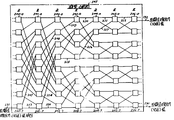
제2도는 본 발명의 주체인 제1도와 패킷 스위치의 블록선도.2 is a block diagram of FIG. 1 and a packet switch, which are subjects of the present invention.
제3도 내지 제10도는 트렁크 제어기(104)의 입력에서 트렁크 제어기(109)의 입력까지 패킷의 통신동안 수행된 패킷 변형도.3 through 10 illustrate packet modifications performed during communication of packets from the input of the
제11도는 패킷 스위치(107)의 스위치 노드(200-7)에 대한 상세 블록선도.11 is a detailed block diagram of the switch node 200-7 of the
제12도는 스위치 노드(200-7)의 입력 제어(1101)에 대한 상세 블럭선도.12 is a detailed block diagram of
제13도는 어드레스 회전 회로(1206)에 대한 상세 블록선도.13 is a detailed block diagram of the address rotation circuit 1206. FIG.
제14도는 스위치 노드(200-7)의 출력 제어 (1102)에 대한 상세 블록선도.14 is a detailed block diagram of
* 도면의 주요부분에 대한 부호의 설명* Explanation of symbols for main parts of the drawings
100 : 중앙처리기 102 : 트렁크 제어기100: central processor 102: trunk controller
107 : 패킷 스위치 1104 : 분배 플립플롭107: packet switch 1104: distributed flip-flop
1100 : 입력 제어 1102 : 출력 제어1100: input control 1102: output control
1200 : 입력 시프트 레지스터 1202 : 길이 레지스터1200: input shift register 1202: length register
1203 : 버퍼 시프트 레지스터 1205 : 데이타 선택기1203: buffer shift register 1205: data selector
1206 : 어드레스 회전 회로 1207 : 멀티플렉서1206: address rotation circuit 1207: multiplexer
본 발명은 정보 신호의 패킷 교환에 대한 방법 및 패킷 교환 구조(architecture)에 관한 것이다. 특히 본 발명은 패킷내의 어드레스 정보에 입각한 패킷의 경로를 선택하고 교환망을 통하여 교대 경로를 정하는 경로 선택 분배 계위로 배열된 고속 패킷 스위치의 통합 회로망을 갖는 패킷 교환 구조에 관한 것이다.The present invention relates to a method and packet exchange architecture for packet exchange of information signals. In particular, the present invention relates to a packet-switched structure having an integrated network of high-speed packet switches arranged in a path selection distribution hierarchy that selects a path of a packet based on address information in the packet and alternates a path through the switching network.
자기 경로 선택 교환 노드를 사용하는 것과 같은 패킷 교환망은 패킷에 포함된 어드레스 정보를 기초로 하여 패킷을 통신한다. 이러한 자기 경로 선택망에서는, 일반적으로 그 교환망의 각 입력과 출력쌍 사이에 단지 하나의 유일한 경로 선택단이 있다. 이 특성은 교환망내의 장애 교환 노드가 그 노드만을 분배하는 두 경로의 교차점에 위치될 수 있으므로 장애 진단을 쉽게 한다. 단지 하나의 유일한 경로 선택의 존재로 인한 문제는 신뢰성 및 역량을 감소시켜 불균형된 통신량 조건하에서 동작한다는 것이다. 신뢰성은 단일 노드 또는 노드들간의 링크의 결함으로 많은 경로선택을 이용할 수 없게 하기 때문에 문제이다. 통신량 문제는 특정한 통신량 패턴으로 많은 양의 통신을 하는 다수의 경로 선택이 하나의 노드를 통하여 전달되기 때문에 발생한다. 이것이 일어날때, 이들 경로상와 통신 용량은 단일 노드의 것에 제한된다.Packet-switched networks, such as those using self-path selection switching nodes, communicate packets based on address information contained in the packets. In such a magnetic path selection network, there is generally only one unique path selection between each input and output pair of the switching network. This feature facilitates fault diagnosis because a fault-switching node in the switching network can be located at the intersection of two paths that distribute only that node. The problem with the existence of only one unique path selection is that it operates under unbalanced traffic conditions by reducing reliability and capacity. Reliability is a problem because a single node or a link failure between nodes makes many path choices unavailable. Traffic problems arise because a large number of path selections, with a large amount of communication in a particular traffic pattern, are carried through one node. When this happens, the communication capacity on these paths is limited to that of a single node.
자기 경로 선택 패킷 교환망의 포텐셜 신뢰성 및 통신량 문제점을 극복하는 한 방법은 패킷 교환망이 트렁크(trunk) 제어기에 의해 양단에서 종단된 각 트렁크를 갖는 트렁크들에 의해 상호 접속되는 고속 패킷 시스템을 포함하는 것이다. 각 교환망은 이중 교환 배열로 구성된다. 결함이 없는 조건동안, 이중 교환망 배열은 명목상으로 동작하고, 어떤 주어진 트렁크 제어기는 이중교환망 배열과 함께 동작하여 각 배열과 그 트렁크 제어기에 부착된 트렁크 사이의 패킷의 경로 선택을 회전 또는 교체시킴으로써 패킷 교환의 작업량을 분배한다. 한 교환 배열이 실패하는 경우에, 그 실패는 패킷을 비실패 교환 배열에만 경로 선택하는 트렁크 제어기에 의해 자동적으로 검출된다. 이 기법은 교환 배열을 이중으로 하는 추가적인 코스트(cost)로 인하여 단일의 비이중 배열보다 비경제적이다. 또한, 통신량의 불균형은 패킷을 경로 선택하는데 유용한 두경로(한 경로는 각 교환 배열을 통함)만이 있으므로 절반으로 감소된다.One way to overcome the potential reliability and traffic problems of self-pathing packet switched networks is to include a high speed packet system in which a packet switched network is interconnected by trunks with each trunk terminated at both ends by a trunk controller. Each switching network consists of a dual switching arrangement. During fault-free conditions, dual-switched network arrangements operate nominally, and any given trunk controller operates with dual-switched network arrangements to exchange packets by rotating or swapping the path selection of packets between each array and trunks attached to that trunk controller. Distribute the work load. If one exchange arrangement fails, the failure is automatically detected by the trunk controller which routes the packet only to the unsuccessful switched arrangement. This technique is less economical than a single non-duplex array due to the additional cost of doubling the swap array. In addition, the traffic imbalance is reduced by half because there are only two paths (one path through each switching arrangement) that is useful for routing packets.
자기 경로 선택 교환망에서 신뢰성 및 통신량 문제점을 완화시키는 한 공지된 방법에는 자기 경로 선택 교환망의 입력에서 밴얀(banyan) 스위칭 노드의 여분 계위를 이용하는 것이 포함되어 상술된 문제점들을 해결한다. 상기 보고는 교환하는 상기 여분단이 교환망의 다른 계위와 동일하고 어드레스하는 여분의 비트를 교환망을 통하여 경로 선택되는 각 패킷의 어드레스 필드에 부가하여 이용되는 것을 제안한다. 여분의 어드레스 비트는 교환망의 외부에서 하드웨어나 소프트웨어는 상기 비트를 사용하여 과중한 통신량을 실패 하거나 위험에 직면하게 되는 노드를 피하게 된다. 보고에 의해 제안된 방법이 교환망을 통하여 하나이상의 경로 선택을 추가하는 것을 허용하는 까닭에, 사용하기 위한 경로 선택은 패킷 교환망의 외부에서 이루어지 는 것을 요구한다.One known method of mitigating reliability and traffic problems in a self-path selection switching network involves using redundant levels of banyan switching nodes at the input of the self-path selection switching network to solve the problems described above. The report suggests that the redundant end being exchanged is the same as another level of the switching network and is used in addition to the addressing field of each packet routed through the switching network. Redundant address bits are used outside the switching network to allow hardware or software to use these bits to avoid nodes that fail heavy traffic or face risk. Since the method proposed by the report allows the addition of more than one route selection through the switched network, the route selection for use requires that it be made outside of the packet switched network.
상술된 문제점은 분배 및 경로 선택 교환의 계위를 구비하는 패킷 교환망이 교환 노드의 불균형된 통신량 상태 및 장애를 보상하는 구성 실시예에서 기술된 바와 같이 본 발명의 원리에 따라 해결될 수 있다. 분배 계위의 교환 노드는 교체 경로 선택 알고리즘을 기초로 하여 패킷을 다운스트림 교환 노드에 경로 선택하는 교환망을 통해서 통신량을 분배하고 다운스트림 교환 노드의 강하를 자동적으로 보상한다. 교환망의 구조는 초기 교환망의 계위가 교환망의 나머지 계위에서 경로 선택 계위에 따르는 교체 분배 및 경로선택 계위를 구비하는 것과 같다. 교체 분배 및 경로 선책 계위 장점은 불균형된 통신량 상태에 연관된 문제점이 교환망의 초기 계위에서 모든 분배 계위의 위치보다도 오히려 더 큰 정도로 보상된다는 것이다. 이유는 초기 경로 선택 계위가 최종 수신처로 패킷을 집중하기 시작하여 다음 분배 노드가 어떠한 과부하된 다운스트림 경로 선택 노드를 더욱 효율적으로 우회하기 때문이다.The above-described problem can be solved according to the principles of the present invention as described in the configuration embodiment where a packet switched network having a hierarchy of distribution and path selection exchanges compensates for unbalanced traffic conditions and failures of the switching node. The switching node in the distribution hierarchy distributes the traffic through the switching network which routes packets to the downstream switching node based on the replacement path selection algorithm and automatically compensates for the drop of the downstream switching node. The structure of the switching network is such that the hierarchy of the initial switching network has an alternate distribution and routing selection hierarchy that conforms to the routing selection hierarchy in the remaining hierarchy of the switching network. The alternate distribution and route preemption advantage is that the problems associated with unbalanced traffic conditions are compensated to a greater extent than the positions of all distribution levels in the initial hierarchy of the switching network. The reason is that the initial path selection hierarchy begins to concentrate packets to the final destination so that the next distribution node more efficiently bypasses any overloaded downstream path selection nodes.
분배 계위에서 각 교환 노드는 교체 교환 알고리즘을 기초로 하여 다운스트림 교환 노드의 서브셋트(subset)중 하나로 패킷을 교체적으로 통신하는 패킷 수신과 다운스트림 교환 노드에서 선택된 노드의 사용 가능성에 응답한다. 경로 선택 계위에서 각 교환 노드는 패킷을 다운스트림 교환 노드로 통신하는 각 패킷에 포함된 어드레스 정보에 응답한다. 각 분배 교환 노드는 신호를 기억하고 이들 신호를 수정하는 수단을 구비하여 그 다음 패킷이 통신될 다운스트림 교환 노드의 서브 셋트중 그 다음것을 경로 선택하도록 한다. 만일 경로 선택된 다운스트림 패킷이 무용하다면, 분배 노드는 자동적으로 패킷을 서브 셋트내의 다른 유용 다운스트림 교환 노도로 경로 선택한다.In the distribution hierarchy, each switching node responds to packet reception to alternately communicate packets to one of a subset of downstream switching nodes based on the replacement switching algorithm and to the availability of the selected node at the downstream switching node. In the path selection hierarchy, each switching node responds to the address information contained in each packet that communicates the packet to the downstream switching node. Each distributed switching node has means for storing signals and modifying these signals to cause the next packet to route-select the next subset of downstream switching nodes to which communications are to be made. If the routed downstream packet is unavailable, the distribution node automatically routes the packet to another useful downstream exchanged denomination in the subset.
유리하게도, 두 경로 선택과 분배 교환 노드는 회로 설계에 있어서 동일하고 외부 신호에 응답하여 경로선택 또는 분배노드의 기능을 수행한다. 이 외부 신호에 응답하여, 경로 선택 계위의 교환 노드는 또한 어드레스 정보를 회전시켜 다운스트림 노드에 의해 즉시 사용되도록 어드레스 정보를 위치시킨다.Advantageously, both path selection and distribution switching nodes are identical in circuit design and perform the function of path selection or distribution node in response to external signals. In response to this external signal, the switching node of the path selection hierarchy also rotates the address information to position the address information for immediate use by the downstream node.
이하 첨부된 도면을 참조하여 본 발명은 더욱 상세히 기술될 것이다.Hereinafter, the present invention will be described in more detail with reference to the accompanying drawings.
제1도는 트렁크(117, 119)와 같은 다수의 고속 트렁크를 취급하는 예시적인 패킷 교환로망을 도시한 것이다. 먼저, 제1도의 패킷 교환망을 구성하는 서브 시스템의 일반적으로 기술이 주어진 다음, 패킷 스위치 (107)와 본 발명의 촛점인 그 구성요소들에 대한 기술이 주어진다. 제1도에서 도시된 바와 같이, 패킷 스위치(107)은 다수의 트렁크 제어기로 단말처리되고 중앙 처리기의 트렁크 제어기(102)를 통하여 중앙 처리기(100)와 협력한다. 트렁크에 전송된 각 트렁크 패킷은 그 패킷이 패킷 교환망을 통해서 취해지는 경로 선택을 지정하는 논리 어드레스를 포함한다. 각 트렁크 제어기는 논리 어드레스를 수신처 트렁크 제어기에 패킷을 전달하도록 스위치(107)에 의해 사용된 스위치 어드레스로 변환하기 위해 번역 테이블을 포함하고 있는 메모리로 이루어져 있다. 번역 정보는 호출 설정 및 호출 회답 패킷에 응답하여 트렁크 제어기(102) 및 스위치 (107)를 통하여 중앙 처리기(100)에 의해 각 트렁크 제어기의 메모리내에 기억된다. 스위치(107)의 전체적인 기능을 설명하기 위해서, 트렁크 제어기(104, 108)와 스위치 (107)를 통하여 트렁크(118)에서 트렁크(119)까지 제3도에 도시된 패킷의 경로 선택을 고려한다. 제3도에서 도시된 패킷의 수신시에, 트렁크 제어기(104)는 제4도에 도시된 바와 같이 스위치 패킷내에 트렁크 패킷을 어셈블한다. 스위치 패킷은 플래그 필드와 스위치(107)를 통하여 패킷을 트렁크 제어기(108)에 경로 선택하는데 필요한 정보를 제외하고는 제3도의 트렁크 패킷의 모든 정보를 포함한다. 스위치(107)는 수신처 트렁크 제어기 필드에 응답하여 상기 경로 선택을 수행한다. 스위치(107)로부터 나온 스위치 패킷의 수신에 응답하여, 트렁크 제어기(108)는 트렁크 제어기(104)에 의해 수신된 최초의 트렁크 패킷을 제거시키고, 필요한 플래그 필드를 부가하여, 트렁크(119)상에 상기 트렁크 패킷을 전송한다.1 illustrates an example packet switched network that handles multiple high speed trunks, such as
패킷 스위치(107)는 제2도에 보다 상세히 도시되어 있다. 스위치(107)는 다수의 스위치 노드 계위를 포함한다. 각 노드 계위는 분배 노드 또는 경로 선택 노드중 하나로 구성되고 각각 분배 또는 경로 계위라고 불려져 있다. 예를 들어, 분배 노드(200-0) 내지 (200-7)은 분배 계위(200)로 구성된다. 경로 선택 노드는 수신처 트렁크 제어기 필드의 최상위 어드레스에 응답하여 적당한 출력 링크를 선택차고 그 다음 경로 선택 노드의 준비로 수신처 트렁크 제어기 필드내에 포함된 어드레스를 우측으로 한 비트 회전시킨다. 분배 노드는 스위치 패킷에 응답하여 내부 플립플롭에 의해 정해진 출력상에 스위치 패킷을 재전송하려고 자동적으로 시도한다. 그러나, 만일 소정의 출력 링크가 통화중이면, 분배 노드는 연결된 다른 출력 링크상에 스위치 패킷을 전송한다. 내부 플립플롭은 각 패킷의 전송후에, 토글(toggle)된다. 그 결과는 분배 노드가 스위치 패킷의 전송시에 출력 링크 사이를 교체하도록 시도한다는 것이다.
각 분배 노드가 두 출력 링크중 한 링크상에 수신된 스위치 패킷을 전송하므로, 어느 한 트렁크 제어기에서 수신처 트렁크 제어기로 패킷 스위치를 통하여 전송하는 동안 패킷이 취해지는 스위치(107)를 통하여 여러 경로가 존재한다. 스위치 (107)를 통하여 어떤 두 트렁크 제어기 사이에 유용한 다른 경로 선택을 도시하기 위해서 두가지 실시예가 지금부터 주어진다. 실시예는 트렁크 제어기(104, 108) 사이의 패킷 전송을 가정 하고 또한 이들 두 경로 선택에 대한 각각의 분배 계위의 분배 플립플롭이 소정의 값을 갖고 제1경로 선택 이 링크(207, 208, 209, 210, 211, 212)에 있는 식으로 링크가 유용하다고 가정한다. 분배 플립플롭의 상태로 인하여 제2경로 선택은(213, 214, 215, 216, 217, 212)일 것이다.Since each distributed node transmits the received switch packet on one of the two output links, there are multiple paths through the
트렁크 제어기(104)가 제3도에 도시된 바와 같이 트렁크 패킷을 수신할때, 제어기 (104)는 필요한 어드레스 번역 및 어셈블리 동작을 수행하여 제4도에 도시된 바와 같이 상기 트렁크 패킷을 스위치 패킷으로 변환한다. 트렁크 제어기에 의해 트렁크 패킷을 스위치 패킷으로의 변형은 상술된 제이. 에스. 튜너케이스 5에서 상세히 기술되어 있어서 여기서는 반복하지 않는다. 제4도에 도시된 스위치 패킷의 형성후에, 트렁크 제어기(104)는 도선(131)를 통하여 상기 스위치 패킷을 노드(200-7)에 전송한다. 노드(200-7)가 분배 노드이 므로, 그 자체의 출력에 연결된 두 링크중 한 링크에 스위치 패킷을 경로 선택한다. 노드(200-7)가 링크(207)를 통하여 스위치 패킷을 노드(210-3)에 경로 선택한다고 가정하자. 링크(207)를 통하여 경로 선택된 스위치 패킷의 구성은 제5도에 도시되어 있고 제4도의 스위치 패킷과 동일하다. 노드(210-3)는 제5도에 도시된 바와 같이 "0"인 수신처 트렁크 제어기 필드의 최상위 비트에 응답하여 링크(208)를 통하여 패킷을 노드(202-1)에 경로 선택한다. 노드(201-3)도 또한 스위치 패킷에 응답하여 수신처 트렁크 제어기 필드를 좌측으로 1비트만큼 회전시킨다. 수신처 트렁크 제어기 필드의 상기 회전 효과는 제6도에 도시되어 있고 이는 노드(202-1)에 전송된 패킷이다.When
노드(202-1)는 분배 노드이고 본 예로서, 노드(204-0)의 내부 플립플롭이 링크(209)를 지정한다고 가정 하여 링크(208)를 통하여 수신된 스위치 패킷을 링크(209)를 통하여 노드(203-0)에 경로 선택한다. 링크(209)를 통하여 경로 선택 패킷은 제7도에 도시되어 있다. 노드(203-0)가 경로 선택 노드이므로, 이는 수신처 트렁크 제어기 필드의 최상위 비트에 응답하여 링크(210)를 통하여 스위치 패킷을 노드(204-0)에 경로 선택한다. 링크(210)를 통하여 경로 선택된 스위치 패킷은 제8도에 도시되어 있다. 제8도에 도시된 바와 같이, 노드(203-0)는 수신처 트렁크 제어기 필드상 좌회전을 수행한다. 노드(204-0)는 노드(204-0)의 내부 플립플롭이 링크(211)를 지정한다고 가정하여 링크(210)를 통하여 수신된 스위치 패킷을 링크(211) 를 통하여 노드(205-0)에 전송한다. 노드(205-0)에 전송된 패킷은 제9도에 도시되어 있다. 경로 선택 노드인 노드(205-0)는 "0"인 수신처 제어 필드의 최상위 비트를 갖는 스위치 패킷에 응답하여 제10도에 도시된 바와 같이 수신처 트렁크 제어기 필드를 회전시킨 후에 링크(212)를 통하여 노드(206-0)에 상기 패킷을 경로 선택한다. 또한 경로 선택 노드인 노드(206-0)는 "1"인 수신처 트렁크 제어기 필드의 최상위 비트에 응답하여 도선(132)을 통하여 트렁크 제어기(108)에 상기 패킷을 경로 선택한다.Node 202-1 is a distribution node and, as an example, assumes that an internal flip-flop of node 204-0 designates link 209, it sends link 209 to switch packets received over
트렁크 제어기 (104)로부터 그들의 내부 분배 플립플롭의 소정의 상태로 인하여 두 링크 사이의 패킷을 분배 노드가 교대로 경로 선택한다고 가정하는 트렁크 제어기(108)까지 기술된 제2경로를 지금부터 기술하기로 한다. 제4도에 도시된 스위치 패킷에 응답하여, 노드(200-7)는 링크(123)를 통하여 노드(201-7)에 상기 패킷을 경로 선택한다. 경로 선택인 패킷은 제5도에 도시된 것과 동일하다. 노드(201-7)는 "0"인 수신처 트렁크 제어기 필드의 최상위 비트에 응답하여 링크(214)를 통하여 노드(202-3)에 상기 패킷을 경로 선택한다. 링크(214)를 통하여 경로 선택된 패킷은 제6도에 도시되어 있다. 노드(202-3)는 그 패킷에 응답하여 그 패킷이 링크(215)를 통하여 노드(203-3)에 경로 선택한다고 가정하면, 수신처 트렁크 제어기 필드의 최상위 비트간 "0"이므로 노드(203-0)는 그 패킷에 응답하여 링크(216)를 통하여 노드(204-1)에 그 패킷을 경로 선택한다. 노드(204-1)는 그 패킷에 응답하여 링크(217)를 통하여 노드(205-0)에 패킷을 경로 선택한다. 노드(205-0)는 "0"인 수신처 트렁크 제어기 필드의 최상위 비트에 응답하여 노드(206-0)에 링크(212)를 통하여 패킷을 경로 선택한다. 노드(206-0)에 경로 선택된 패킷은 제10도에 도시되어 있다. 앞의 경로 선택에서와 같이, 노드(206-0)는 패킷에 응답하여 그 패킷을 도선(132)을 통하여 트렁크 제어기(108)에 전송한다.From now on we will describe a second path described from
스위치 노드(200-7)는 제11도에 보다 상세히 도시되어 있다. 노드(200-7)는 입력 제어 유니트(1100, 1101)와 출력 제어 유니트(1102, 1103)를 구비한다. (200-7)과 같은 분배 노드는 (201-7)과 같은 경로 선택 노드와 설계상 동일하고 가로안의 번호는 제11도가 노드(201-7)를 도시하는 케이스에 대한 링크의 연결을 표시한다. 노드의 두형의 사이의 차이점은 노드가 도선(1112)을 통하여 노드(200-7)의 경우에서 디스에이블 신호를 수신하는지 또는 수신하지 않는지의 여부이다. 만일 노드가 디스에이블 신호를 수신한다면, 노드는 경로 선택 기능을 수행하고 반면에 노드가 디스에이블 신호를 수신하지 않는다면, 노드는 분배 기능을 수행한다. 노드(200-7)가 분배 노드이므로, 디스에이블 신호는 도선(1112)을 통하여 전송되지 않는다. 도선(131)상에 수신된 패킷에 응답하여, 입력 제어(1101)는 분배 플립플롭(1105)의 상태가 "0"일때 상기 패킷을 케이블(1110)을 통하여 출력 제어(1102)에 경로 선택하려고 시도하거나, 또는, 입력 제어(1101)는 분배 플립플롭(1105)의 상태가 "1"일때 케이블(111)을 통하여 출력 제어(1103)에 상기 패킷을 경로 선택하려고 시도한다. 만일 분배 플립플롭(1105)에 의해 지정된 출력 제어기 통신중이면, 입력 제어(1101)는 다른 출력 제어에 패킷을 경로 선택하려고 시도한다. 출력 제어가 통신중인지를 결정하기 위해서, 입력 제어(1101)는 케이블(1110, 1111)을 통하여 요청 및 인가 신호의 전송을 이용한다. 예를 들어, 출력 제어(1102)가 통신중인지의 여부를 결정하려면, 입력 제어(1101)는 케이블(1110)을 통하여 출력 제어(1102)에 요청 신호를 전송 한다. 만일 출력 제어(1102)가 유휴이면, 제어(1102)는 입력 제어(1101)에 다시 인가 신호를 전송한다. 인가 신호의 수인시에, 입력 제어(1101)는 케이블(1110)을 통하여 출력 제어 (1102)에 패킷의 전송을 개시한다. 입력 제어(1100)는 설계 및 동작상 입력 제어 (1101)와 동일하다.Switch node 200-7 is shown in more detail in FIG. 11. The node 200-7 includes
출력제어(1102)는 링크(207)를 모니터하고 후술한 바와 같이, 링크(207)가 통신중인지 아니면 유휴인지의 여부를 내부적으로 기억한다. 일력 제어(1101 또는 1100)중 어느 하나로부터 나온 데이타의 수신시에, 출력 제어(1102)는 상기 정보를 링크(207)를 통하여 노드(201-3)에 재전송한다. 출력 제어(1103)는 설계 및 기능상 출력 제어 (1102)와 유사하다.The
상술된 바와 같이, 경로 선택 노드는 노드(200-7)와 같은 분배 노드와 설계상 동일하다. 경로 선택 노드에 의해 수행된 기능은 분배 노드와는 다른데 그 이유는 경로 선택 노드가 트렁크 수신처 제어 필드의 최상위 비트에 응답하여 패킷이 어느 출력 제어에 경로 선택되어지는가를 결정하기 때문이다. 예를 들어, 만일 노드(200-7)가 도선(1112)를 통하여 디스에이블 신호를 수신한다면, 노드(200-7)는 다음의 경로 선택 노드 기능을 수행할 것이다. 입력 제어(1101)는 링크상에 수신된 패킷에 응답하여 트렁크 수신처 제어 필드의 최상위 비트가 "0"일때, 상기 패킷을 출력 제어(1102)에 경로 선택하거나 또는 트렁크 수신처 제어 필드의 최상위 비트가 "1"일때, 상기 패킷을 출력 제어(1103)에 경로 선택한다. 입력 제어(1101)에서 지정된 출력 제어까지 패킷을 전송하는 동안, 입력 제어(1101)는 트렁크 수신처 제어 필드의 최상위 비트를 최하위 비트 위치로 좌측 이동시킨다. 이 좌측 이동 동작은 그 다음 경로 선택 노드가 트렁크 수신처 제어 필드의 최상위 비트상에 그 자체의 경로 선택 결정의 근거로 할 수 있도록 트렁크 수신처 제어 필드가 적당한 상태로 있는 것을 확실하게 한다.As described above, the path selection node is identical in design to a distribution node such as node 200-7. The function performed by the path selection node is different from the distribution node because the path selection node determines in which output control the packet is routed in response to the most significant bit of the trunk destination control field. For example, if node 200-7 receives the disable signal via lead 1112, node 200-7 will perform the following path selection node function.
노드가 경로 선택 기능을 수행할때, 분배 플립플롭은 사용되지 않는다. 트렁크 수신처 제어 필드의 최상위 비트에 의해 지정된 출력 제어가 통신중이면, 입력 제어는 패킷을 버퍼하고 지정된 출력 제어가 유휴일 때 까지 대기한다.When a node performs a path selection function, a distributed flip-flop is not used. If the output control specified by the most significant bit of the trunk destination control field is in communication, the input control buffers the packet and waits until the specified output control is idle.
입력 제어(1101)는 제12도에 보다 상세히 도시되어 있다. 입력 제어(1101)는 그 자체의 관련된 스위치 노드가 분배 노드나 경로 선택 노드로서 기능하도록 조정될 수 있다. 입력 제어(1101)는 도선(1112)을 거쳐서 백플랜으로부터 선택적으로 연결될 수 있는 인에이블 신호를 거쳐서 분배 또는 경로 선택기능중 어느 한 기능을 수행하도록 구성된다. 분배 노드로 동작할때, 어드레스 레지스터(1201) 및 어드레스 회전 회로(1206)는 제어기 (1204)를 통하여 디스에이블된다. 경로 선택 모드로 동작할때, 분배 플립플롭(1105)은 제어기 (1204)에 의해 디스에이블된다.
스위치 노드(200-7)내의 분배 기능을 수행하는 입력 제어(1101)의 동작을 살펴본다면, 입력 회로(1201)는 케이블(131)을 거쳐 트렁크 제어기(1041)로부터 패킷을 수신하고, 제어기(1204)의 제어하에 케이블(131)을 거쳐 링크 개방 신호를 트렁크 제어기(104)에 전송한다. 링크 개방 신호의 기능은 제14도의 출력 제어(1103)와 관련하여 후술되어 있다. 인입 패킷은 입력 시프트 레지스터(1200)로 시프트된다. 입력 시프트 레지스터(1200)는 패킷의 시작을 나타내는 개시 비트를 검출하는데 이용된다. 입력 시프트 레지스터(1200)로 부터, 패킷은 하나의 완전한 패킷을 버퍼링할 수 있는 버퍼 시프트 레지스터(1203)로 시프트된다. 버퍼 시프트 레지스터(1203)는 64비트 각각이 저장된 후 출력을 제공한다. 제어기(1204)의 제어하에 상기 출력은 데이타 선택기(1205)에 의해 선택될 수 있으며 버퍼 시프트 레지스터(1203)의 사용되지 않는 부분은 통과된다. 이와 같은 통과 기능을 패킷이 출력 회로로 전송되기 시작하기 전에 전체의 패킷을 버퍼시킬 필요가 없을때 및 입력 회로(1100)를 통해 패킷의 전송 속도를 상승시키고자할때 행해진다. 멀티플렉서(1207)는 제어기(1204)의 제어하에 데이타가 전송될 케이블(110 또는 1111)을 선택한다. 입력 제어(1101)는 출력 제어 (1102) 및 링크(207)을 거쳐 스위치 노드(201-3)로 패킷을 분배하던지 출력 제어 (1103) 및 링크(213)을 거쳐 스위치 노드(201-7)로 패킷을 분배한다. 만일 선택된 스위치 노드가 이미 다른 패킷을 수용하고 있다면, 입력 제어(1101)는 두개의 스위치 노드 사이에 패킷을 분배한다.Looking at the operation of
패킷은 케이블(131)을 거쳐 트렁크 제어기(104)로부터 수신되어 도선(1211)을 통해 제공된 시스템 클럭 속도로 레지스터(1200)로 시프트된다. 패킷의 개시가 레지스터(1200)로 완전히 시프트되었다는 것을 나타내는 비트 위치 9에 개시 비트가 도달될때, 도선(1212)상의 신호를 통해 제어기(1204)에 그와 같은 상태를 알린다. 제어기 (1204)가 상기 신호를 수신하면, 입력 제어(1101)는 도선(1232)을 통한 분배 플립플롭(1105)의 상태에 따라 요구 신호를 출력 제어(1102 또는 1103)로 전송한다. 만일, 플립플롭(1165)비 출력이 "0"이면, 이는 출력 제어 (1103)가 처음의 패킷을 수신했다는 것을 나타내며, 제어기(1104)는 요구 신호를 출력 제어(1102)에 전송한다. 플립플롭(1105)의 출력이 "1"이면, 출력제어(1102)는 마지막 패킷을 수신했다는 것을 나타내며, 제어기(1104)는 요구 신호를 출력 제어(1103)에 전송한다. 동시에, 인입된 패킷은 입력 시프트 레지스터(1200)를 통해 버퍼 시프트 레지스터(1203)내로 시프트된다. 플립플롭(1105)이 상태 "0"이라면, 입력 제어(1101)는 요구 신호를 케이블(1110)을 거쳐 출력 제어(1102)에 전송한다. 출력 제어(1102)가 패킷을 수신하도록 준비되는 즉시, 패킷은 케이블(1110)을 통해 입력 제어(1101)에 인가 신호를 보낸다. 상기 인가 신호를 수신함에 따라, 제어기(1204)는 데이타 선택기(1205)로 하여금 레지스터(1203)로 시프트된 패킷을 디스에이블 어드레스 회전 회로(1206), 멀티플렉서 (1207), 케이블(1110)을 거쳐 출력 제어(1102)로 진행하도록 한다. 데이타 선택기(1205)는 인가 신호를 수신함과 동시에 패킷이 출력 제어로 진행하는 것을 허용한다. 이와 같은 방법으로, 전 패킷이 레지스터(1203)에 의해 버퍼될 필요가 없으며, 따라서 패킷의 더욱 빠른 전송을 허용한다. 상기 인가 신호의 존재는 제어기(1204)로 하여금 도선(1231)을 통해 플립플롭(1105)의 상태를 변화시키도록 한다. 따라서, 다음 패킷이 수신될때 제어기(1204)는 요구 신호를 출력 제어(1103)에 전송하게 된다.Packets are received from
만일, 출력 제어(1102)가 선정된 주기내에 요구신호에 응답하지 않는다면, 제어기 (1204)는 출력 제어(1102)에 대한 요구 신호를 제거하고 출력 제어(1103)에 요구 신호를 전송한다. 만일, 출력 제어(1103)가 선정된 주기후에도 도구신호에 응답하지 않는다면, 제어기(1204)는 출력 (1103), (1302)중 어느 하나가 인가 신호에 응답할때 까지 두개의 출력 제어에 각각 요구 신호를 교대로 보낸다. 이와 같은 동작이 발생되는 동안, 인입되는 패킷은 버퍼 시프트 레지스터(1200)에 의해 버퍼된다. 설정된 주기는 도선(1211)을 거쳐 시스템 클럭(134)으로부터 수신된 클럭 펄스를 카운팅하므로써 결정된다.If the
경로 선택 노드(201-l)내의 기능을 수행하는 입력 제어(1101)의 동작을 살펴보면, 상기 동작을 설명하기 위해, 케이블 및 도선 번호는 괄호내에 도시되어 있다. 입력 제어(1101)는 디스에이블 신호를 통해 경로 선택 기능을 수행하도록 구성되는데. 상기 디스에이블 신호는 도선(1121)을 통해 백플랜으로부터 연결된다. 경로 선택 모드로 동작할때, 분배 플립플롭(1105)는 제어기(1204)에 의해 디스에이블된다.Referring to the operation of the
입력 회로(1210)는 노드(200-7)로부터 인입되는 패킷을 수신하고, 제어기 (1204)의 제어하에 케이블(213)을 거쳐 링크 개방 신호를 노드(200-7)에 전송한다. 링크 개방 신호의 기능을 출력 제어(1203)와 관련하여 후술하기로 한다. 입력 시프트 레지스터(1200)는 상술된 바와 같이 개시 비트를 검출하는데 이용된다. 부가로, 입력 시프트 레지스터(1200)는 길이 레지스터(1202)내에 저장된 네트워크 패킷 길이 필드를 추출하며, 어드레스 레지스터(1201)내에 저장된 네트워크 어드레스 필드중의 최상위 비트를 추출하는데 이용된다. 버퍼 시프트 레지스터(1103)는 상술된 바와 같이 하나의 완전한 패킷을 버퍼링하는데 이용된다. 어드레스 회전 회로(1106)는 상술된 바와 같이 패킷의 나머지 부분인 어드레스가 선택된 출력 제어로 전송되기 전에 네트워크 어드레스 필드를 좌측으로 회전시키는 동작을 한다. 제어기(1104)의 제어하에 멀티플렉서(1107)는 인입되는 패킷의 어드레스 필드에 따라 데이타가 전송된 케이블(1110 또는 1111)을 선랙한다. 입력 제어(1101)의 동작은 제5도에 도시된 패킷의 전송을 다루는 실시예를 이용하므로써 더욱 상세히 설명될 것이다. 입력 시프트 레지스터(1200)는 도선(1211)을 거쳐 시스템 클럭(161)에 의해 연속적으로 클럭된다. 데이타가 입력 케이블(213)를 거쳐 수신될때, 데이타는 입력 시프트 레지스터(1200)를 통해 클럭된다. 개시 비트가 입력 시프트 레지스터 (1200)의 비트 위치 (9)에 도달되면, 제어기 (1204)는 상기 비트를 검출하여 도선 (213)상에 펄스를 전송한다. 이 펄스는 길이 레지스트(1202)로 하여금 네트워크 패킷 길이 필드를 저장하도록 하며, 어드레스 레지스터(1201)로 하여금 네트워크 어드레스 필드중의 최상위 비트를 저장하도록 하는데, 상기 최상위 비트는 입력 시프트 레지스터(1200)의 비트 스위치에 존재한다.The
최상위 어드레스 비트는 패킷이 출력 제어(1102)로 전송되어 한다는 것을 나타내는 것이기 때문에, 제어기(1204)는 요구 신호를 도선(1110)을 통해 출력 제어 (1102)에 전송한다. 이와 같은 요구 신호가 전송되면, 데이타는 입력 시프트 레지스터 (1200)에서 다수의 출력 단자를 갖는 버퍼 시프트 레지스터(1203)로 시프트된다. 상기 다수의 출력 단자는 버퍼 시프트 레지스터(1203)내의 다른 비트 위치에 접속된다. 제어기(1204)가 도선(110)을 거쳐 출력 제어(1102)로부터 인가 신호를 수신하면, 제어기(1204)는 버퍼 시프트 레지스터(1203)의 출력에서 패킷의 개시비트가 버퍼 시프트 레지스터(1203)내에 도달되는가를 계산한다. 이는 출력 제어(1102)로 패킷의 전송이 가능한 빨리 이루어지도록 하기 위해 행해진다. 이와 같은 계산을 기초로 하여, 제어기 (1204)는 데이타 선택기(1205)가 버퍼 시프트 레지스터(1203)의 지정된 출력을 선택하도록 제어한다. 제어 정보는 케이블(1217)을 거쳐 데이타 선택기(1205)에 전송된다. 데이타 선택기(1205)는 선택된 출력으로부터의 데이타를 도선(1216)을 거쳐 어드레스 회전 회로(1206)에 전송한다. 데이타가 전송되기전에, 제어기(1204)는 도선(1219)을 거쳐 패킷 신호의 개시를 전송하므로서 어드레스 회선 회로(1206)를 리셋트한다. 그후, 제어기(1204)는 길이 레지스터(1202)내에 저장되어 케이블(1220)을 거쳐 판독되는 패킷 길이 정보를 이용하여, 패킷의 마지막부가 입력 시프트 레지스터내로 인입되는 시간을 결정한다. 상기 동작이 발생하여 시프트 레지스터(1203)로부터 전송이 시작될때, 제어기(1204)는 도선(1205)을 거쳐 링크 개방 신호를 전송한다. 상기 신호는 3단 구동기(1209)와 입력도선(131)을 거쳐 입력 포트(503-60)에 재전송된다. 링크 개방 신호는 입력 제어 (1000)가 다른 패킷을 수신할 준비가 되었다는 것을 나타낸다. 이와 같은 기능은 출력 제어 회로와 함께 후에 기술할 것이다.Since the most significant address bit indicates that the packet is to be sent to the
어드레스 회전 회로(1206)는 제13도에 더욱 상세히 도시되어 있다. 회로(1206)의 목적은 어드레스 필드를 1비트씩 왼쪽으로 회전시켜 최상위 비트가 최하위 비트로 되도록 하는데 있다. 상기 회전은 각 입력 제어가 단지 최상위 비트만을 디코드시키기 때문에 필요하다. 시프트 레지스터(1300), (1303)는 1비트 시프트 레지스 터이며, 데이타 선택기(1302)는 시프트 레지스터 (1300)의 출력이나 시프트 레지스터 (1303)의 출력을 선택하는데 이용되며, 제어 회로(1309)는 어드레스회전 회로의 동작을 제어한다. 제어 회로(1309)가 도선(1219) 을 거쳐 제어기 (1204)로부터 패킷 신호의 개시를 수신할때, 제어 회로는 도선(1307)을 거쳐 시프트 레지스터(1300)에, 도선(1305)을 거쳐 시프트 레지스터(1303)에 클럭 신호를 전송한다. 제어 회로(1309)는 도선 (1218)상부로 전송될 시프트 레지스터(1303)의 출력을 선택하도록 도선(1308)을 거쳐 데이타 선택기(1302) 를 조정한다. 그후, 제어 회로(1309)는 도선(1218)을 거쳐 전송될 비트의 수를 계산한다. 네트워크 어드레스 필드의 최상위 비트가 시프트 레지스터(1303)내에 포함될때, 제어 회로(1309)는 도선(1305)을 거쳐 시프트 레지스터(1303)로의 클럭 신호 전송을 중지하며, 데이타 선택기(1302)를 조정하여 시프트 레지스터 (1300)의 출력을 선택하도록 한다 그후, 제어 회로(1309)는 네트워크 어드레스 필드의 나머지 비트가 도선 (118)를 거쳐 전송될때까지 기다린다. 이와 같은 상태에서, 제어 회로(1309)는 시프트 레지스터(1303)로 출력 신호를 전송하기 시작하며, 데이타 선택기(1302)를 조정하여 시프트 레지스터(1303)의 출력을 선택하도록 한다. 이와 같은 동작은 네트워크 어드레스 필드의 최상위 비트가 회전되는 결과를 낳게한다.The address rotation circuit 1206 is shown in more detail in FIG. The purpose of the circuit 1206 is to rotate the address field left by one bit so that the most significant bit is the least significant bit. This rotation is necessary because each input control only decodes the most significant bit. The shift registers 1300 and 1303 are 1-bit shift registers, and the
출력 제어 (1103)는 제14도에 더욱 상세히 도시되어 있다. 제어 회로(1400)는 입력 제어(1100), (1101)로부터 케이블(1108), (1111)을 거쳐 전송되는 요구 신호에 응답한다. 만일, 플립플롭(1401)이 세트되면, 제어 회로(1400)는 상술된 케이블중 하나를 거쳐 요구된 입력 제어에 인가 신호를 전송하므로써 상기 요구 신호에 응답하게 된다. 상기 요구에 응답을 한후, 제어 회로(1400)는 데이타 선택기(1403)를 조정하여 적절한 케이블(1108 또는 1111)로부터의 데이타 도선을 선택한다. 제어 회로(1400)는 적절한 제어 정보를 케이블(1408) 을 거쳐 데이타 선택기(1403)에 전송한다. 데이타 선택기(1403)는 선택된 입력 단자상에 수신된 정보를 도선(1407)으로 전송한다. 3단 장치 (1402)는 도선(1407)상의 정보를 취하여 링크(213)를 거쳐 이들 데이타를 스위치 노드(201-7)의 부분인 입력 회로에 전송한다. 제어회로(1400)는 도선(1409)을 거쳐 3단 장치 (1402)의 출력을 제공한다.
제14도에 도시된 출력 제어(1103)의 동작은 데이타의 패킷을 케이블(1111)을 통하여 전달하는 입력 제어 (1101)의 실시예를 고찰함으로써 더욱 상세히 설명될 것이다. 입력 제어 (1101)가 도선(1111)을 통하여 요구 신호를 전달할때, 만일 링크가 다른 입력 제어 회로중 하나에 의해서 사용되지 않고 플립플롭(1401)의 출력이 셋트되면 제어 회로(1400)는 도선(1111)을 통하여 인가 신호를 입력 제어(1101)에 전송한다. 플립플롭 (1401)이 셋트된다고 가정을 하면, 제어 회로(1400)는 인가 신호를 입력 제어 (1001)에 전송하고 케이블(1408)을 통하여 데이타 선택기(1403)를 조정하여 도선(1111)상에 전송되는 데이타를 선택하고 이 데이타를 도선(1407)에 재전송한다. 또한, 제어 회로(1400)는 3단 장치(1402)를 인에이블하여 도선(1407)상의 정보를 링크 (213)에 전송한다.The operation of the
입력 제어(1101)가 전 패킷을 전송할 후에는, 도선(1111)에서 요구 신호를 제거시킨다. 일단 한번 요구 신호가 도선(1111)에서 제거되면, 제어 회로(1400)는 요구 신호를 도선(1409)을 통하여 플립플롭(1401)에 전송한다. 일단 스위치 노드(201-7)의 입력 제어가 다른 패킷을 수신할 수 있게 되면, 도선(1406), 3단 장치(1411), 링크(213)를 통하여 개방 링크 신호를 전송한다. 개방 링크 신호는 5입력에 의해 플립플롭 (1401)을 셋트시킨다. 일단 플립플롭(1401)이 셋트되면, 제어 회로(1400)는 입력 제어에서 나온 요구 신호에 다시 한번 응답한다.After the
상술된 실시예는 단지 본 발명의 원리를 설명하기 위한 것에 불과하므로, 본 기술에 숙련된 사람에 의해서 본 발명의 사상 및 범주를 벗어남이 없이 다른 장치가 고안될 수 있다.Since the above-described embodiments are merely illustrative of the principles of the present invention, other devices may be devised by those skilled in the art without departing from the spirit and scope of the present invention.
Claims (5)
Applications Claiming Priority (3)
| Application Number | Priority Date | Filing Date | Title |
|---|---|---|---|
| US562,176 | 1983-12-16 | ||
| US06/562,176 US4550397A (en) | 1983-12-16 | 1983-12-16 | Alternate paths in a self-routing packet switching network |
| US562176 | 1983-12-16 |
Publications (2)
| Publication Number | Publication Date |
|---|---|
| KR850005055A KR850005055A (en) | 1985-08-19 |
| KR930001746B1 true KR930001746B1 (en) | 1993-03-12 |
Family
ID=24245126
Family Applications (1)
| Application Number | Title | Priority Date | Filing Date |
|---|---|---|---|
| KR1019840008007A KR930001746B1 (en) | 1983-12-16 | 1984-12-15 | Self-routing packet switching network |
Country Status (7)
| Country | Link |
|---|---|
| US (1) | US4550397A (en) |
| EP (1) | EP0169208B1 (en) |
| JP (1) | JPS61500758A (en) |
| KR (1) | KR930001746B1 (en) |
| CA (1) | CA1227859A (en) |
| DE (1) | DE3469334D1 (en) |
| WO (1) | WO1985002737A1 (en) |
Families Citing this family (76)
| Publication number | Priority date | Publication date | Assignee | Title |
|---|---|---|---|---|
| DE3476503D1 (en) * | 1984-06-01 | 1989-03-02 | Bell Telephone Mfg | Multiple memory loading system |
| US4656622A (en) * | 1984-09-26 | 1987-04-07 | American Telephone And Telegraph Company | Multiple paths in a self-routing packet and circuit switching network |
| US4661947A (en) * | 1984-09-26 | 1987-04-28 | American Telephone And Telegraph Company At&T Bell Laboratories | Self-routing packet switching network with intrastage packet communication |
| US4621359A (en) * | 1984-10-18 | 1986-11-04 | Hughes Aircraft Company | Load balancing for packet switching nodes |
| GB8511758D0 (en) * | 1985-05-09 | 1985-06-19 | Emi Ltd | Data communications systems |
| US4805091A (en) * | 1985-06-04 | 1989-02-14 | Thinking Machines Corporation | Method and apparatus for interconnecting processors in a hyper-dimensional array |
| US4742511A (en) * | 1985-06-13 | 1988-05-03 | Texas Instruments Incorporated | Method and apparatus for routing packets in a multinode computer interconnect network |
| US4670871A (en) * | 1985-06-27 | 1987-06-02 | American Telephone And Telegraph Company, At&T Bell Laboratories | Reliable synchronous inter-node communication in a self-routing network |
| US4630260A (en) * | 1985-06-27 | 1986-12-16 | At&T Bell Laboratories | Self-routing multipath packet switching network with sequential delivery of packets |
| CA1265227A (en) * | 1985-07-08 | 1990-01-30 | Reginhard Pospischil | Method for monitoring and controlling the traffic in digital transmission networks |
| US4665514A (en) * | 1985-08-02 | 1987-05-12 | American Telephone And Telegraph Company, At&T Bell Laboratories | Integrated voice/data network |
| DE3687400T2 (en) * | 1985-11-04 | 1993-07-15 | Ibm | DIGITAL NEWS TRANSMISSION NETWORKS AND STRUCTURE OF TRANSMISSION WAYS IN THESE NETWORKS. |
| GB8528892D0 (en) * | 1985-11-23 | 1986-01-02 | Int Computers Ltd | Multi-node data processing system |
| US4679189A (en) * | 1985-11-27 | 1987-07-07 | American Telephone And Telegraph Company | Alternate routing arrangement |
| US4688213A (en) * | 1985-11-29 | 1987-08-18 | Rca Corporation | Asynchronous random access communication system with collision resolution based on time of arrival |
| US4696000A (en) * | 1985-12-12 | 1987-09-22 | American Telephone And Telegraph Company, At&T Bell Laboratories | Nonblocking self-routing packet and circuit switching network |
| US4751697A (en) * | 1986-09-05 | 1988-06-14 | American Telephone And Telegraph Company, At&T Bell Laboratories | Distributed packet switching sytem |
| US4780870A (en) * | 1986-09-05 | 1988-10-25 | American Telephone And Telegraph Company, At&T Bell Laboratories | Packet switch |
| US4821259A (en) * | 1986-09-05 | 1989-04-11 | American Telephone And Telegraph Company, At&T Bell Laboratories | Control information communication arrangement for a distributed control switching system |
| US4774707A (en) * | 1986-09-10 | 1988-09-27 | General Electric Company | Random access communication system with scheduled data transmission and asynchronous contention scheduling |
| US4745593A (en) * | 1986-11-17 | 1988-05-17 | American Telephone And Telegraph Company, At&T Bell Laboratories | Arrangement for testing packet switching networks |
| US4745599A (en) * | 1987-01-05 | 1988-05-17 | General Electric Company | Random access communication system with contention scheduling of subpacketized data transmissions and scheduled retransmission of unsuccessful subpackets |
| CA1297567C (en) * | 1987-02-06 | 1992-03-17 | Kazuo Hajikano | Self routing-switching system |
| US5050069A (en) * | 1987-04-27 | 1991-09-17 | Thinking Machines Corporation | Method and apparatus for simulating m-dimension connection networks in and n-dimension network where m is less than n |
| EP0310759B1 (en) * | 1987-09-30 | 1993-06-16 | Siemens Aktiengesellschaft | Sorting unit for a switching node with multiple digital switches for fast asynchronous data switching networks |
| US4905233A (en) * | 1987-11-23 | 1990-02-27 | Harris Corporation | Multiple path routing mechanism for packet communications network |
| GB8817288D0 (en) * | 1988-07-20 | 1988-08-24 | Racal Milgo Ltd | Methods of & networks for information communication |
| GB8821409D0 (en) * | 1988-09-13 | 1988-10-12 | Int Computers Ltd | Data processing system |
| US5119367A (en) * | 1988-10-28 | 1992-06-02 | Oki Electric Industry Co., Ltd. | Method and a node circuit for routing bursty data |
| AU637988B2 (en) * | 1988-11-10 | 1993-06-17 | Zigmantas Leonas Budrikis | Distributed router of connectionless packets over connection oriented networks |
| WO1990005419A1 (en) * | 1988-11-10 | 1990-05-17 | Zigmantas Leonas Budrikis | Distributed router of connectionless packets over connection oriented networks |
| US5023864A (en) * | 1989-05-08 | 1991-06-11 | At&T Bell Laboratories | Crossover network utilizing two-dimensional arrays of nodes |
| US5077483A (en) * | 1989-05-08 | 1991-12-31 | At&T Bell Laboratories | Network topology for reduced blocking and photonic system implementation thereof |
| US5258978A (en) * | 1989-05-08 | 1993-11-02 | At&T Bell Laboratories | Space-division switching network having reduced functionality nodes |
| US5122892A (en) * | 1989-05-08 | 1992-06-16 | At&T Bell Laboratories | Space-division switching network having reduced functionality nodes |
| US5175765A (en) * | 1989-05-09 | 1992-12-29 | Digital Equipment Corporation | Robust data broadcast over a distributed network with malicious failures |
| US5455865A (en) * | 1989-05-09 | 1995-10-03 | Digital Equipment Corporation | Robust packet routing over a distributed network containing malicious failures |
| US5020055A (en) * | 1989-06-23 | 1991-05-28 | May Jr Carl J | Multi-length packet format including fixed length information words |
| US5020054A (en) * | 1989-06-23 | 1991-05-28 | May Jr Carl J | Packet format including unique network identity |
| US5001706A (en) * | 1989-06-23 | 1991-03-19 | At&T Bell Laboratories | Packet cross connect switch system including improved throughput |
| US4962498A (en) * | 1989-06-23 | 1990-10-09 | At & T Bell Laboratories | Multi-length packet format including check sequence(s) |
| US5042032A (en) * | 1989-06-23 | 1991-08-20 | At&T Bell Laboratories | Packet route scheduling in a packet cross connect switch system for periodic and statistical packets |
| US5003535A (en) * | 1989-06-23 | 1991-03-26 | At&T Bell Laboratories | Packet synchronization utilizing a multi-length packet format including check sequences |
| US4979165A (en) * | 1989-06-23 | 1990-12-18 | At&T Bell Laboratories | Multiple queue bandwidth reservation packet system |
| US5016243A (en) * | 1989-11-06 | 1991-05-14 | At&T Bell Laboratories | Automatic fault recovery in a packet network |
| US4993015A (en) * | 1989-11-06 | 1991-02-12 | At&T Bell Laboratories | Automatic fault recovery in a packet network |
| US4999829A (en) * | 1989-11-06 | 1991-03-12 | At&T Bell Laboratories | Automatic fault recovery in a packet network |
| CA2032620C (en) * | 1989-12-22 | 1995-08-15 | Takafumi Chujo | Method for searching for alternate path in communication network |
| JP2834253B2 (en) * | 1990-02-07 | 1998-12-09 | 株式会社日立製作所 | Packet exchange |
| EP0446493B1 (en) * | 1990-03-14 | 1994-11-30 | Alcatel N.V. | Routing logic means for a communication switching element |
| FR2662564B1 (en) * | 1990-05-22 | 1992-07-31 | Alcatel Nv | SELF-ROUTING MULTI-PATH SWITCHING NETWORK FOR SWITCHING ASYNCHRONOUS TIME-MULTIPLEXED CELLS WITH AVAILABILITY SIGNALING. |
| US5179552A (en) * | 1990-11-26 | 1993-01-12 | Bell Communications Research, Inc. | Crosspoint matrix switching element for a packet switch |
| US5197064A (en) * | 1990-11-26 | 1993-03-23 | Bell Communications Research, Inc. | Distributed modular packet switch employing recursive partitioning |
| US5124978A (en) * | 1990-11-26 | 1992-06-23 | Bell Communications Research, Inc. | Grouping network based non-buffer statistical multiplexor |
| US5166926A (en) * | 1990-12-18 | 1992-11-24 | Bell Communications Research, Inc. | Packet address look-ahead technique for use in implementing a high speed packet switch |
| US5157654A (en) * | 1990-12-18 | 1992-10-20 | Bell Communications Research, Inc. | Technique for resolving output port contention in a high speed packet switch |
| US5321813A (en) | 1991-05-01 | 1994-06-14 | Teradata Corporation | Reconfigurable, fault tolerant, multistage interconnect network and protocol |
| US5398236A (en) * | 1993-05-26 | 1995-03-14 | Nec America, Inc. | Asynchronous transfer mode link recovery mechanism |
| WO1995003657A1 (en) * | 1993-07-21 | 1995-02-02 | Fujitsu Limited | Atm exchange |
| KR100327699B1 (en) * | 1993-07-30 | 2002-07-22 | 브리티쉬 텔리커뮤니케이션즈 파블릭 리미티드 캄퍼니 | Telecommunication network transmitting signal through multipath and its operation method |
| US5453979A (en) * | 1994-01-27 | 1995-09-26 | Dsc Communications Corporation | Method and apparatus for generating route information for asynchronous transfer mode cell processing |
| US5452293A (en) * | 1994-01-27 | 1995-09-19 | Dsc Communications Corporation | Apparatus and method of transmitting call information prior to establishing a connection path |
| US5528592A (en) * | 1994-01-27 | 1996-06-18 | Dsc Communications Corporation | Method and apparatus for route processing asynchronous transfer mode cells |
| US5452294A (en) * | 1994-07-05 | 1995-09-19 | Motorola, Inc. | Method and apparatus for adaptive route selection in communication networks |
| US6745240B1 (en) | 1999-11-15 | 2004-06-01 | Ncr Corporation | Method and apparatus for configuring massively parallel systems |
| US6412002B1 (en) | 1999-11-15 | 2002-06-25 | Ncr Corporation | Method and apparatus for selecting nodes in configuring massively parallel systems |
| US6418526B1 (en) | 1999-11-15 | 2002-07-09 | Ncr Corporation | Method and apparatus for synchronizing nodes in massively parallel systems |
| US6519697B1 (en) | 1999-11-15 | 2003-02-11 | Ncr Corporation | Method and apparatus for coordinating the configuration of massively parallel systems |
| US20070110079A1 (en) * | 2004-07-19 | 2007-05-17 | Gero Schollmeier | Method and network nodes for reporting at least one dropped-out connection path withing a communication network |
| US8194655B2 (en) * | 2004-08-05 | 2012-06-05 | Dust Networks, Inc. | Digraph based mesh communication network |
| US7881239B2 (en) * | 2004-03-27 | 2011-02-01 | Dust Networks, Inc. | Low-powered autonomous radio node with temperature sensor and crystal oscillator |
| US7961664B1 (en) | 2004-03-27 | 2011-06-14 | Dust Networks, Inc. | Digraph network subnetworks |
| US8059629B1 (en) | 2004-03-27 | 2011-11-15 | Dust Networks, Inc. | Digraph network timing synchronization |
| US7529217B2 (en) * | 2004-03-27 | 2009-05-05 | Dust Networks, Inc. | Low-power autonomous node for mesh communication network |
| US7420980B1 (en) * | 2004-03-27 | 2008-09-02 | Dust Networks, Inc. | Digraph network superframes |
| US9069672B2 (en) * | 2009-06-12 | 2015-06-30 | Intel Corporation | Extended fast memory access in a multiprocessor computer system |
Family Cites Families (8)
| Publication number | Priority date | Publication date | Assignee | Title |
|---|---|---|---|---|
| US4201891A (en) * | 1978-03-17 | 1980-05-06 | International Telephone And Telegraph Corporation | Expandable digital switching network |
| IT1108325B (en) * | 1978-04-10 | 1985-12-09 | Cselt Centro Studi Lab Telecom | ROAD PROCEDURE AND DEVICE FOR A PACKAGE SWITCHING COMMUNICATION NETWORK |
| FR2429534A1 (en) * | 1978-06-19 | 1980-01-18 | Cit Alcatel | MULTIPLEX CONNECTION NETWORK WITH INCREASED QUALITY OF SERVICE |
| FR2447652A1 (en) * | 1979-01-24 | 1980-08-22 | Materiel Telephonique | OPERATOR FOR PACKET DIGITAL DATA SWITCHING NETWORK |
| JPS5726955A (en) * | 1980-07-25 | 1982-02-13 | Hitachi Ltd | Backup control system |
| JPS58150349A (en) * | 1982-03-02 | 1983-09-07 | Mitsubishi Electric Corp | Packet communication network |
| US4512011A (en) * | 1982-11-01 | 1985-04-16 | At&T Bell Laboratories | Duplicated network arrays and control facilities for packet switching |
| US4484326A (en) * | 1982-11-04 | 1984-11-20 | At&T Bell Laboratories | Packet load monitoring by trunk controllers |
-
1983
- 1983-12-16 US US06/562,176 patent/US4550397A/en not_active Expired - Lifetime
-
1984
- 1984-05-11 DE DE8484902167T patent/DE3469334D1/en not_active Expired
- 1984-05-11 EP EP84902167A patent/EP0169208B1/en not_active Expired
- 1984-05-11 WO PCT/US1984/000713 patent/WO1985002737A1/en active IP Right Grant
- 1984-05-11 JP JP59501967A patent/JPS61500758A/en active Granted
- 1984-10-09 CA CA000464967A patent/CA1227859A/en not_active Expired
- 1984-12-15 KR KR1019840008007A patent/KR930001746B1/en not_active IP Right Cessation
Also Published As
| Publication number | Publication date |
|---|---|
| KR850005055A (en) | 1985-08-19 |
| JPS61500758A (en) | 1986-04-17 |
| US4550397A (en) | 1985-10-29 |
| JPH0584694B2 (en) | 1993-12-02 |
| EP0169208A1 (en) | 1986-01-29 |
| CA1227859A (en) | 1987-10-06 |
| DE3469334D1 (en) | 1988-03-17 |
| WO1985002737A1 (en) | 1985-06-20 |
| EP0169208B1 (en) | 1988-02-10 |
Similar Documents
| Publication | Publication Date | Title |
|---|---|---|
| KR930001746B1 (en) | Self-routing packet switching network | |
| US4656622A (en) | Multiple paths in a self-routing packet and circuit switching network | |
| US4630260A (en) | Self-routing multipath packet switching network with sequential delivery of packets | |
| CA1234208A (en) | Self routing packet switching network with intrastage packet communication | |
| EP0823164B1 (en) | System and method for dynamic network topology exploration | |
| EP0404337B1 (en) | High-speed mesh connected local area network | |
| US5654695A (en) | Multi-function network | |
| US5889776A (en) | Physical layer switch system for ethernet local area network communication system | |
| US4679186A (en) | Alternate self-routing packet switching node having fault detection capabilities | |
| CA2100235C (en) | Switch-based microchannel planar apparatus | |
| CA2020238C (en) | Growable packet switch architecture | |
| EP0405208B1 (en) | Multistage network with distributed pipelined control | |
| JPH088590B2 (en) | Packet switching network with multiple packet destinations | |
| US7660239B2 (en) | Network data re-routing | |
| EP1471698A2 (en) | Network fabric access device with multiple system side interfaces | |
| JP3811007B2 (en) | Virtual connection protection switching | |
| WO2000079739A1 (en) | Apparatus and method for queuing data | |
| US7379456B2 (en) | Network routing apparatus | |
| US6993035B2 (en) | System for routing data packets through a crossbar switch in expansion mode | |
| US7009986B2 (en) | Network apparatus | |
| EP0505782A2 (en) | Multi-function network | |
| JP3309212B2 (en) | Network switch device | |
| KR0164966B1 (en) | The multistage interconnection network with the folded structure and loop-back function | |
| EP1835673A1 (en) | Network fabric access device with multiple system side interfaces | |
| JPH0685160B2 (en) | Multi-stage network system |
Legal Events
| Date | Code | Title | Description |
|---|---|---|---|
| A201 | Request for examination | ||
| E902 | Notification of reason for refusal | ||
| G160 | Decision to publish patent application | ||
| E701 | Decision to grant or registration of patent right | ||
| GRNT | Written decision to grant | ||
| FPAY | Annual fee payment |
Payment date: 20020307 Year of fee payment: 10 |
|
| LAPS | Lapse due to unpaid annual fee |