KR920009645B1 - Zirconium base fuel cladding resistant to pci crack propagation - Google Patents
Zirconium base fuel cladding resistant to pci crack propagation Download PDFInfo
- Publication number
- KR920009645B1 KR920009645B1 KR1019850001652A KR850001652A KR920009645B1 KR 920009645 B1 KR920009645 B1 KR 920009645B1 KR 1019850001652 A KR1019850001652 A KR 1019850001652A KR 850001652 A KR850001652 A KR 850001652A KR 920009645 B1 KR920009645 B1 KR 920009645B1
- Authority
- KR
- South Korea
- Prior art keywords
- cladding tube
- tubular member
- alloy
- nuclear fuel
- fuel material
- Prior art date
Links
Images


Classifications
-
- G—PHYSICS
- G21—NUCLEAR PHYSICS; NUCLEAR ENGINEERING
- G21C—NUCLEAR REACTORS
- G21C3/00—Reactor fuel elements and their assemblies; Selection of substances for use as reactor fuel elements
- G21C3/02—Fuel elements
- G21C3/04—Constructional details
- G21C3/16—Details of the construction within the casing
- G21C3/20—Details of the construction within the casing with coating on fuel or on inside of casing; with non-active interlayer between casing and active material with multiple casings or multiple active layers
-
- C—CHEMISTRY; METALLURGY
- C22—METALLURGY; FERROUS OR NON-FERROUS ALLOYS; TREATMENT OF ALLOYS OR NON-FERROUS METALS
- C22C—ALLOYS
- C22C16/00—Alloys based on zirconium
-
- C—CHEMISTRY; METALLURGY
- C22—METALLURGY; FERROUS OR NON-FERROUS ALLOYS; TREATMENT OF ALLOYS OR NON-FERROUS METALS
- C22F—CHANGING THE PHYSICAL STRUCTURE OF NON-FERROUS METALS AND NON-FERROUS ALLOYS
- C22F1/00—Changing the physical structure of non-ferrous metals or alloys by heat treatment or by hot or cold working
- C22F1/16—Changing the physical structure of non-ferrous metals or alloys by heat treatment or by hot or cold working of other metals or alloys based thereon
- C22F1/18—High-melting or refractory metals or alloys based thereon
- C22F1/186—High-melting or refractory metals or alloys based thereon of zirconium or alloys based thereon
-
- Y—GENERAL TAGGING OF NEW TECHNOLOGICAL DEVELOPMENTS; GENERAL TAGGING OF CROSS-SECTIONAL TECHNOLOGIES SPANNING OVER SEVERAL SECTIONS OF THE IPC; TECHNICAL SUBJECTS COVERED BY FORMER USPC CROSS-REFERENCE ART COLLECTIONS [XRACs] AND DIGESTS
- Y02—TECHNOLOGIES OR APPLICATIONS FOR MITIGATION OR ADAPTATION AGAINST CLIMATE CHANGE
- Y02E—REDUCTION OF GREENHOUSE GAS [GHG] EMISSIONS, RELATED TO ENERGY GENERATION, TRANSMISSION OR DISTRIBUTION
- Y02E30/00—Energy generation of nuclear origin
- Y02E30/30—Nuclear fission reactors
Abstract
내용 없음.No content.
Description
제1도는 피복관의 횡 단면도.1 is a cross-sectional view of the cladding tube.
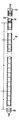
제2도는 수냉식 원자로 연료 요소와 부분 단면도.2 is a partial cross-sectional view of a water cooled reactor fuel element.
제3도는 피복체의 종방향 평면을 나타내는 제2도에 도시된 연료 요소중 농축부의 확대 단면도.3 is an enlarged cross-sectional view of the enrichment portion of the fuel element shown in FIG. 2 showing the longitudinal plane of the coating.
* 도면의 주요부분에 대한 부호의 설명* Explanation of symbols for the main parts of the drawings
1 : 피복관 9 : 내부 표면1: coating tube 9: inner surface
10 : 외부층 100 : 내부층10: outer layer 100: inner layer
200 : 저부 플러그 210 : 스프링200: bottom plug 210: spring
220 : 단부 캡 230 : 플리넘220: end cap 230: plenum
300 : 연료봉 400 : 연료 펠릿300: fuel rod 400: fuel pellets
410 : 단부 420 : 연부410: end 420: edge
450,460 : 간극450,460: gap
본 발명은 지르콘늄 베이스 합금을 사용하는 핵연료 물질을 수용하기 위한 피복관에 관한 것이며, 상기 합금은 수냉식 원자로 연료 요소에서 펠릿-피복체간 상호 작용(PCI)의 역효과를 최소화하는 성질을 갖는다.The present invention relates to cladding for accommodating nuclear fuel material using a zirconium base alloy, which has the property of minimizing adverse effects of pellet-cover interaction (PCI) in water cooled reactor fuel elements.
전체적으로 높은 지르코늄 합금으로 만들어진 피복관의 사용이 수냉식 원자로 산업에 이용되어 왔다. 사용된 공동 합금의 예로는 지르칼로이 -2, 지르칼로이 -4 및 지르코늄 -2.5중량%(w/o) 니오븀(niobium)등이 있다. 이들 합금들은 그들의 핵특성, 기계적 성질, 그리고 고온 수성 부식 저항성등에 기초를 두고 선택되어 진다.The use of cladding made entirely of high zirconium alloys has been used in the water cooled reactor industry. Examples of the co-alloys used include zircaloy -2, zircaloy -4 and zirconium -2.5 wt% (w / o) niobium. These alloys are chosen based on their nuclear properties, mechanical properties, and high temperature aqueous corrosion resistance.
지르칼로이 -2 및 4의 개발과 지르칼로이 -1 및 3의 포기에 관한 이야기는 ASTM 특별 기술 공보제368(1964)호 페이지 3-27에서 스탠리 카스에 의한 "지르칼로이의 개발"에 요약되어 있다. 상기 문헌은 여기에 참고로 서술하였다. 또한 지르칼로이 개발에 관한 연구는 미합중국 특허 공보 제2,772,964 ; 3,097,094 ; 및 3,148,055호에 서술되어 있다.The story of the development of Zircaloy-2 and 4 and the abandonment of Zircaloy-1 and 3 is summarized in the Development of Zircaloy by Stanley Kass in ASTM Special Technical Publication 368 (1964), page 3-27. . This document is described herein by reference. In addition, research on the development of zircaloys is described in US Patent Publication Nos. 2,772,964; 3,097,094; And 3,148,055.
지르칼로이 -2 및 4에 대한 가장 상업적인 화학적 규정치는 예를들어 ASTM B350-80(합금 UNS 제R60802 및 R60804)에 나타나 있는 조건과 일치하여야 한다. 이 조건에 추가하여 이들 합금의 산소 함량은 900-1600ppm 사이이지만 보통 1200±200ppm이다.The most commercial chemical regulations for Zircaloy -2 and 4 should be consistent with the conditions shown, for example, in ASTM B350-80 (alloys UNS R60802 and R60804). In addition to these conditions, the oxygen content of these alloys is between 900-1600 ppm but is usually 1200 ± 200 ppm.
지르칼로이 피복관를 제조하기 위한 공통적인 제조 공정은 다음과 같다. 즉 주괴를 중간 크기의 빌리트(billet) 또는 로그(log)로 고온 작업하며; 빌리트를 베타 용액 처리하며; 중공 빌리트를 기계 가공하며 ; 중공 빌리트를 중공 원통형 돌출체로 하기 위해 고온 알파 추출을 하며 ; 다수의 냉각 필거 감소 패스를 통해 상기 돌출체를 최종의 크기를 갖는 피복체로 축소하며, 각 패스 이전에 알파 재결정 서냉을 갖는 것이다. 냉각 작업된 최종 크기의 피복체는 그때 최종 서냉된다. 상기 최종 서냉은 응력 제거 서냉, 부분 재결정 서냉 또는 완전한 재결정 서냉일 수가 있다. 사용되는 최종 서냉의 형태는 연료 피복체의 기계적 성질에 대한 설계자의 규정에 따라 선택된다.A common manufacturing process for producing a zircaloy cladding tube is as follows. That is, the ingot is hot worked with medium size billets or logs; Billet is treated with beta solution; Machine hollow billets; Hot alpha extraction to make the hollow billet a hollow cylindrical protrusion; Through multiple cooling filter reduction passes, the protrusions are reduced to the final sized coating, with alpha recrystallization slow cooling before each pass. The cooled final sized coating is then finally slow cooled. The final slow cooling may be stress relief slow cooling, partial recrystallization slow cooling or complete recrystallization slow cooling. The type of final slow cooling used is selected in accordance with the designer's specifications for the mechanical properties of the fuel cladding.
상기 언급한 피복체를 이용한 연료봉의 사용시에 일어나는 하나의 문제는 열 팽창 되는 산화 연료 펠릿과 접촉함에 의해 추가된 응력을 받게되는 피복체의 내부 표면으로부터 일어나는 파손의 발생이다. 이들 파손은 가끔 피복체의 벽두께를 통해 전파되어 연료봉 전체를 파괴함으로써 냉각제를 봉으로 흐르게 하며, 방사능 분열 생성물이 노심을 통해 순환하는 1차 냉각제를 오염하게 한다. 이들 파손 현상은 조사 강도, 기계적 응력 및 분열 생성물의 상호 작용에 기인하여 지르코늄 함금내에 연쇄 파손을 일으키게 한다고 믿어진다.One problem that arises in the use of fuel rods with the aforementioned coatings is the occurrence of breakage from the inner surface of the coating which is subjected to the added stress by contacting the thermally expanded oxidizing fuel pellets. These breaks sometimes propagate through the wall thickness of the coating, destroying the entire fuel rod, causing the coolant to flow into the rod, and causing the radioactive fission product to contaminate the primary coolant circulating through the core. These break phenomena are believed to cause chain breakage in zirconium alloys due to the interaction of irradiation strength, mechanical stress and cleavage products.
내부 표면에 결합된 지르코늄 층을 갖는 지르칼로이 연료 피복관은 수냉식 원자로의 작동중 연료 펠릿과 피복체 사이의 경계에서 발생하는 연쇄 파손에 저항성이 있어야 한다는 것을 알 수 있다. 이러한 조건을 만족하는 예로는 미합중국 특허 공보 제4,372,817 ; 4,200,492 ; 및 4,390,497호에 서술되어 있다.It can be seen that a zircaloy fuel cladding tube having a zirconium layer bonded to the inner surface must be resistant to chain breakage occurring at the boundary between the fuel pellet and the cladding during operation of the water cooled reactor. Examples of satisfying these conditions include US Patent Publication Nos. 4,372,817; 4,200,492; And 4,390,497.
상기 특허 공보의 지르코늄 라이너(Zirconium liner)는 수성 부식에 대한 저항성을 고려하지 않고 PCI 연쇄 파손에 대한 저항성을 기초로 선택되었다. 만약 피복체가 원자로내에서 파손 되었다면 피복체 내부에 냉각재를 도입하게 되며, 라이너의 수성 부식 저항성은 피복체 용적을 구성하는 고 지르코늄 합금의 것보다 상당히 빈약할 것이라고 생각된다. 이러한 상태에서 라이너는 완전히 산화되어 신속히 불필요하게 되지만 피복체의 지르코늄 합금부에 증가된 하이드라이드 형성을 유도하여 지르코늄 합금의 구조적인 완전성을 내포하게 된다. 피복체의 질적 저하는 상당히 높은 온도의 방출 또는 우라늄 및 방사능 족을 냉각재에 유출하게 되는 원인이 된다.The zirconium liner of this patent publication was selected based on resistance to PCI chain breakage without considering resistance to aqueous corrosion. If the cladding is broken in the reactor, coolant is introduced into the cladding, and the aqueous corrosion resistance of the liner is considered to be considerably poorer than that of the high zirconium alloy constituting the cladding volume. In this state, the liner is completely oxidized and quickly becomes unnecessary, but induces increased hydride formation in the zirconium alloy portion of the coating to imply the structural integrity of the zirconium alloy. Qualitative degradation of the coating causes the release of significantly higher temperatures or the release of uranium and radioactive groups into the coolant.
따라서 본 발명은 핵연료 물질을 함유하기 위한 피복관에 있으며, 외부 관형 부재의 내부에 위치한 내부 관형 부재를 포함하는 것과, 내부 관형 부재의 전체 외부 원주 표면에 걸쳐 외부 관형 부재의 내부 원주 표면에 결합되는 내부 관형 부재의 외부 원주 표면을 포함하는 것과, 상기 외부 관형 부재는 지르칼로이 -2 및 지르칼로이 -4형 합금 그리고 1.0-3.0w/o Nb를 함유하는 Zr-Nb 합금으로부터 선택된 제1합금으로 구성되는 반면 내부 관형 부재는 합금중 350ppm의 산소를 포함하는 부수적인 불순물과 균형 지르코늄을 가지며, 완전히 재결정화된 입자 구조와 최소한 0.003인치의 벽두께를 가지며, 0.1-0.6w/o 주석, 0,07-0.24w/o 철, 0.05-0.15w/o 크롬 및 0.05w/o 정도의 니켈을 함유하는 제2합금으로 구성되는 것을 특징으로 한다.The present invention thus relates to a cladding tube containing nuclear fuel material, comprising an inner tubular member located inside the outer tubular member, the inner being coupled to the inner circumferential surface of the outer tubular member over the entire outer circumferential surface of the inner tubular member. An outer circumferential surface of the tubular member, wherein the outer tubular member is comprised of a first alloy selected from Zircaloy-2 and Zircaloy-4 type alloys and a Zr-Nb alloy containing 1.0-3.0 w / o Nb. The inner tubular member, on the other hand, has balanced zirconium with ancillary impurities containing 350 ppm of oxygen in the alloy, a fully recrystallized grain structure and a wall thickness of at least 0.003 inches, 0.1-0.6 w / o tin, 0,07- And a second alloy containing 0.24 w / o iron, 0.05-0.15 w / o chromium and about 0.05 w / o nickel.
상기 조성 범위에서 주석 함량은 0.2-0.6중량%, 좀더 바람직한 것은 0.3-0.5중량%로 유지되는 것이 바람직하다. 또한 부수적인 불순물의 총량은 1500ppm 이하, 좀더 바람직한 것은 1000ppm 이하로 제한되는 것이 바람직하다. 추가로 산소 및 질소 함량은 각각 250ppm 및 40ppm 이하로 제한되는 것이 바람직하다.Tin content in the composition range is preferably maintained at 0.2-0.6% by weight, more preferably 0.3-0.5% by weight. In addition, it is preferable that the total amount of incidental impurities is limited to 1500 ppm or less, more preferably 1000 ppm or less. In addition, the oxygen and nitrogen contents are preferably limited to 250 ppm and 40 ppm or less, respectively.
특히 표 I 에 도시된 합금은 연료 요소 PCI 장벽으로 사용하기에 아주 적당한 것으로 간주된다. 물론 표 I 의 합금은 주석, 산소, 질소 및 전체적인 부수 불순물 함량에 관해 상기 언급한 양호한 기술에 따라 수정되어도 상관없다.In particular, the alloys shown in Table I are considered to be very suitable for use as fuel element PCI barriers. Of course, the alloys of Table I may be modified according to the good techniques mentioned above with regard to tin, oxygen, nitrogen and the overall incident impurities content.
[표 I]TABLE I

* 전체적으로 약 1500ppm 이하로 유지되는 부수적인 불순물(산소 및 질소 포함)을 제하고 지르코늄은 이들 합금의 균형을 이루는 물질이다.Zirconium is a balance material for these alloys, with the exception of incidental impurities (including oxygen and nitrogen) that remain below about 1500 ppm overall.
본 발명은 좀더 명확히 이해하기 위해서 그 양호한 실시예가 부수도면을 참고로 서술될 것이다.The present invention will be described with reference to the accompanying drawings in order to more clearly understand the present invention.
제1도를 참고하면, 피복관(1)은 관형 부재 또는 내부층(100)에 결합된 관형 부재 또는 외부층(10)을 포함하고 있다. 외부층(10)은 원자로의 수정 부식에 대한 우수한 저항성, 높은 강도 그리고 낮은 크립율을 갖는 제1지르코늄 합금으로 형성된다. 상기 제1지르코늄 합금은 지르칼로이 -2합금, 지르칼로이 -4 합금 또는 지르코늄 -2.5w/o 니오븀과 같은 지르코늄-니오븀 합금등이 바람직하다. 내부층은 제2지르코늄 베이스 합금으로 형성되며, 상기 제2합금은 펠릿 피복체의 상호 작용 효과에 기인하는 연속 파괴에 대한 적재 저항성 뿐만 아니라 수성 부식에 대한 저항성을 갖도록 본 발명자에 의해 설계된 것이다. 내부층은 0.003-0.0045인치 사이의 벽 두께를 갖는 것이 바람직하다. 상기 제2합금의 조성 범위가 표 I에 나타나 있으며, 다음과 같은 이론에 기초를 두고 선택되었다.Referring to FIG. 1, the cladding tube 1 includes a tubular member or
철과 크롬에 주석을 더하는 것과 니켈의 선택적인 첨가는 지르코늄의 수성 부식 저항성을 강화시킨다. 그러나 주석과 산소는 지르코늄의 고체 용액 강화제이다. 철, 크롬 그리고 니켈은 Zr(Fe,Ni,Cr) 침전의 형성을 통하여 약간의 추가된 강성을 제공한다. 상기 원소들은 또한 지르코늄의 크립율을 감소시키며, 원자로의 작동 온도 근처에서 중성자 조사 결함을 서냉하기 위한 지르코늄의 능력을 감소하여 물질의 조사 강도를 증가시킨다. 요약하면 주석, 철, 니켈 및 크롬은 지르코늄의 수성 부식성을 개선하는 반면 또한 PCI 관련 파손의 확산을 정지하기 위한 지르코늄의 성능에 해를 주게 된다.The addition of tin to iron and chromium and the optional addition of nickel enhance the aqueous corrosion resistance of zirconium. However, tin and oxygen are solid solution enhancers of zirconium. Iron, chromium and nickel provide some added stiffness through the formation of Zr (Fe, Ni, Cr) precipitates. The elements also reduce the creep rate of zirconium and increase the irradiation intensity of the material by decreasing the ability of zirconium to slow neutron irradiation defects near the reactor's operating temperature. In summary, tin, iron, nickel and chromium improve the aqueous corrosiveness of zirconium, while also detrimental to the ability of zirconium to stop the spread of PCI-related failures.
주석의 함량은 0.1-0.6중량%로 그리고 산소의 함량을 350ppm 이하, 좀더 바람직하게는 250ppm 이하로 제한함에 의해 이들 합금의 크립율과 응력 경감율은 매우 높아져 피복체의 외부를 만드는 상업용 지르코늄 합금에 비해 PCI 파손 확산에 대한 효과적이고 강화된 저항성을 제공하게 된다. 또한 주석 함량을 0.2-0.6중량%로 유지할 때 높은 크립율, 낮은 중성자 조사 강도 및 수성 부식 저항성의 최적 조합을 얻을 수 있다고 믿어진다. 0.2-0.6중량%, 좀더 바람직한 것은 0.3-0.5중량%의 양호한 주석의 범위에서 BWR작동 조건하의 합금 크립율은 350ppm 이하의 산소를 함유하는 지르코늄의 크립율과 비교하면, 지르코늄의 파손 확산 저항성을 갖는 장벽을 만들게 되지만 중요한 것은 상업적인 지르칼로이 -2혹은 지르칼로이 -4와 동일한 부식 저항성을 갖는다는 것이다. 추가로 한 합금의 주석, 철, 크롬 및 니켈 함량은 그의 재결정화된 입자 크기를 지르코늄에서 관찰된 것보다 훨씬 미세하게 만들어 준다.By limiting the tin content to 0.1-0.6% by weight and the oxygen content to 350ppm or less, more preferably 250ppm or less, the creep rate and stress relief rate of these alloys are very high, resulting in commercial zirconium alloys making the exterior of the coating. In comparison, it provides effective and enhanced resistance to the spread of PCI damage. It is also believed that an optimum combination of high creep rate, low neutron irradiation strength and aqueous corrosion resistance can be obtained when maintaining tin content at 0.2-0.6% by weight. In the range of good tin of 0.2-0.6% by weight, more preferably 0.3-0.5% by weight, the alloy creep rate under BWR operating conditions has a fracture diffusion resistance of zirconium as compared to the creep rate of zirconium containing 350 ppm or less of oxygen. The barrier is created, but the important thing is that it has the same corrosion resistance as commercial Zircaloy-2 or Zircaloy-4. In addition, the tin, iron, chromium and nickel content of one alloy makes its recrystallized particle size much finer than that observed with zirconium.
또한 수성 부식 저항성 및 PCI 파손 확산 저항성에 역효과를 갖는 질소는 65ppm 이하, 좀더 바람직하게는 40ppmm 이하로 제한되는 것이 바람직하다. ASTM 350-80의 표 I에 수록된 모든 다른 부수적인 불순물은 합금 60802 혹은 60804에 대해 도시된 요구치에 부합되는 것이 바람직하다. 부수적인 불순물(산소 및 질소를 포함)의 총량은 축적된 역효과를 최소화하기 위해 1500ppm 이하, 가장 바람스럽게는 1000ppm이하로 유지하여 부수적인 불순물이 조사 강도를 갖도록 하는 것이 바람직스럽다. ASTM B350-80의 표 I 은 여기에 참고로 기록되어 있다.In addition, it is preferable that nitrogen having an adverse effect on aqueous corrosion resistance and PCI breakage diffusion resistance is limited to 65 ppm or less, more preferably 40 ppm or less. All other incidental impurities listed in Table I of ASTM 350-80 preferably meet the requirements shown for alloy 60802 or 60804. It is desirable that the total amount of incidental impurities (including oxygen and nitrogen) be kept below 1500 ppm and most preferably below 1000 ppm in order to minimize accumulated adverse effects so that the incidental impurities have irradiation intensity. Table I of ASTM B350-80 is incorporated herein by reference.
본 출원에 서술된 피복 화학의 조건은 모든 합금 원소 및 불순물을 제조하는 주괴 단계와 간질성 원소, 산소, 수소 및 질소에 대한 공출단계 근처에서와 같은 제조의 중간 단계에서 화학적 분석을 수행함에 의해 부합될 것이라는 것을 알아야 한다. 최종 크기를 갖는 피복체의 화학적 분석은 필요없다.The conditions of the coating chemistry described in the present application are matched by performing chemical analysis in the intermediate stages of manufacture, such as near the ingot stage for producing all alloying elements and impurities and for the evaporation of interstitial elements, oxygen, hydrogen and nitrogen. It should be known. No chemical analysis of the coating having the final size is necessary.
내부층의 관형 출발 성분은 아래의 표 II에 도시된 공칭 조성을 갖는 두 개의 합금을 형성하기 위해 필요한 합금 첨가물과 함께 예를들어 상업적으로 유용한 지르코늄을 제1아아크 용융함에 의해 편리하게 제조될 수 있다.The tubular starting component of the inner layer can be conveniently prepared, for example, by first arc melting commercially useful zirconium with the alloying additives needed to form two alloys having the nominal composition shown in Table II below.
[표 II]TABLE II

형성된 주괴는 그때 베타 용액 처리 단계를 포함하는 종래의 지르칼로이 1차 제조 기술에 의해 내부층을 위한 관형 출발 성분으로 제조된다. 외부층을 위한 관형 지르칼로이 출발 성분은 약 900-1600ppm 사이의 산소 함량을 가지며 등급 R60802 또는 R60804용 ASTM B350-80의 요구치에 부합하는 주괴로부터 종래 방식으로 제조된다. 내부 및 외부층용 이들 관형 출발 성분은 냉각작업, 고온작업, 알파서냉, 또는 베타 켄칭 미세 구조물을 갖는다.The formed ingot is then made into a tubular starting component for the inner layer by conventional Zircaloy primary manufacturing techniques comprising a beta solution treatment step. Tubular Zircaloy starting components for the outer layer are conventionally prepared from ingots having an oxygen content between about 900-1600 ppm and meeting the requirements of ASTM B350-80 for grades R60802 or R60804. These tubular starting components for the inner and outer layers have a cooling, hot working, alpha slow cooling, or beta quenching microstructure.
내부층 출발 성분의 외부 직경 표면 뿐만 아니라 외부층 출발 성분의 내부 직경 표면은 서로의 내부에 안착되었을 때 성분들 사이의 간격이 최소가 되도록 기계 작업된다. 기계 작업된 후 결합될 표면으로부터 최대한 모든 표면 오염물을 제거하기 위해 성분들은 세척된다. 세척후 결합될 부품 표면은 서로 용접될때까지 깨끗한 격실 상태하에 유지되는 것이 바람직하다. 그리하여 결합될 표면의 재오염이 최소화된다. 부품은 다시 서로의 내부에 안착되며, 인접 부품의 접경에 형성된 환상부는 폐쇄되도록 용접된 진공 전자 비임이며, 상기 진공은 안착된 부품의 양단부를 용접한 후 환상으로 유지된다.The inner diameter surfaces of the outer layer starting components as well as the outer diameter surfaces of the inner layer starting components are machined such that the spacing between the components is minimal when seated inside each other. After machining, the components are washed to remove as much of the surface contaminants as possible from the surfaces to be joined. The parts surfaces to be joined after cleaning are preferably kept in a clean compartment until welded together. Thus, recontamination of the surface to be joined is minimized. The parts are again seated inside each other, and the annular portions formed at the borders of the adjacent parts are vacuum electron beams welded to be closed, and the vacuum is annular after welding both ends of the seated components.
이 단계에서, 결합되지 않은 관 외피 조립체는 완전히 지르칼로이로 만들어진 피복관을 제조하기 위해 사용되는 공지의 추출, 냉각 필거링 및 서냉 공정에 따라 처리된다. 종래의 지르칼로이 윤활, 세척, 직선화 및 최종 표면 처리 기술은 1982년 1월 29일 출원된 계류중인 미합중국 특허 출원 제343,788 및 343,787호에 서술된 종래 및 새로운 공정의 어떠한 방법을 사용하여도 무방하다. 모든 상기 제조 공정은 피할 수 없는 결합선 오염의 최소의 중요하지 않은 지역을 제외하고는 층의 완전하고 연속적인 금속적 결합을 이루게 될 것이다.In this step, the unbound tube sheath assembly is treated according to known extraction, cooling pilgering and slow cooling processes used to produce sheaths made entirely of zircaloy. Conventional Zircaloy lubrication, cleaning, straightening and final surface treatment techniques may use any of the conventional and novel processes described in pending US patent applications 343,788 and 343,787, filed January 29, 1982. All of the above manufacturing processes will result in complete and continuous metallic bonding of the layers except for the least critical areas of inevitable bond line contamination.
본 발명을 실시하는 데는 필요 없지만 1982년 1월 29일 출원된 미국특허 출원 제343,788호에 서술된 바와 같이, 레이저 혹은 유도 가열에 의한 표면 베타 처리는 확실히 바람직한 것이다. 사용시 그러한 처리는 끝에서 두 번째 그리고 마지막 사이의 냉각 필거링 패스 혹은 끝에서 두번재 이전에 냉각 필거 패스에 의해 수행된다. 어느 경우에도 관은 필요시 표면 베타 처리 이전에 직선화될 뿐만 아니라 중각 서냉을 갖도록 하는 것이 바람직하다. 표면 베타 처리후에 모든 중간 뿐만 아니라 최종 서냉도 600℃ 이하, 좀더 바람직한 것은 550℃ 이하에서 수행되어야 한다. 가장 바람직한 것은 최후 서냉이 약 500℃에서 수행되는 것이 바람직하다. 이러한 저온 서냉은 베타 표면 처리에 의해 부여된 강화된 부식 저항을 갖도록 하기 위해 사용된다.Although not necessary to practice the invention, as described in US Patent Application No. 343,788, filed Jan. 29, 1982, surface beta treatment by laser or induction heating is certainly preferred. In use, such treatment is performed by a cold filler pass between the second and the end of the end or by a cold filler pass before the second end. In either case, it is desirable that the tube not only be straightened before surface beta treatment, but also have a slow middle cooling. After surface beta treatment all intermediate as well as final slow cooling should be carried out below 600 ° C, more preferably below 550 ° C. Most preferably, the last slow cooling is carried out at about 500 ° C. This low temperature slow cooling is used to have the enhanced corrosion resistance imparted by the beta surface treatment.
표면 베타 처리는 베타 표면 처리된 중간 크기관의 벽두께중 외부층(10)의 약 40% 정도만 위드만스타튼미세 구조를 생성하지만, 그러한 처리에 의해 생성된 강화된 수성 부식 저항성은 그 지역에 한정되는 것이 아니고 내부층 뿐만 아니라 외부층을 통해서도 신장되는 것이 바람직하며 냉각 필거링 및 서냉 후에도 유지 된다는 것을 알아야 한다. 외부층 및 내부층의 가장 바람직한 수성 부식 저항성은 검은 접착성 부식막이며, 24시간 500℃, 1500psi 증기 테스트후에 중량 이득이 200㎎/dm2이하, 좀더 바람직한 것은 100㎎/dm2이하이다.Surface beta treatment produced only 40% of the
표면 베타 처리가 사용되었던 안되었던 간에 최종 냉각 필거링 패스가 있은후 최종 서냉은 지르코늄 합금 내부층이 약 1/10 이하, 좀더 바람직한 것은 1/10-1/20 사이의 입자 크기로 최소한 완전히 재결정화 되는 것이며, 내부층 벽의 두께와 지르칼로이 외부층은 최소한 완전한 응력 제거 서냉이 이루어진다. 최종 서냉이 있은후 종래의 지르칼로이 관 세척, 직선화, 최종의 크기 조정 및 마무리 단계가 수행된다.The final slow cooling after the final cooling pilgering pass, whether or not surface beta treatment was used, resulted in at least a complete recrystallization of the zirconium alloy inner layer of about 1/10 or less, more preferably 1 / 10-1 / 20. The thickness of the inner layer wall and the Zircaloy outer layer are at least complete stress relief slow cooling. After the final slow cooling, conventional Zircaloy tube cleaning, straightening, final sizing and finishing steps are performed.
마무리 된 다음 선형 피복체는 분열성 연료 물질의 적재를 위한 준비를 한다. 용접 밀봉한 비등수형 원자로 연료봉의 양호한 실시예가 제2도 및 3도에 도시되어 있다. 제3도에 도시된 바와같이, 연료봉(300)은, 두께가 약 0.003인치이고, 예를들어 상기 서술한 바와같이 합금 A 또는 B로 형성되는 내부층(100)에 금속적으로 결합된 외부층(10)을 갖는 피복관(1)를 이용하고 있다. 피복체의 전체 벽 두께는 0.029-0.032인치 사이가 바람직하다. 피복관(1)내에 포함되어 있는 것은 본 발명에 따라서 피복관(1)의 내경보다 약 0.008인치 더 작은 직경을 갖는 원통형 연료 펠릿(400)이다.After finishing, the linear cladding is ready for loading of the fissile fuel material. A preferred embodiment of a welded boiling water reactor nuclear fuel rod is shown in FIGS. 2 and 3. As shown in FIG. 3, the
본 발명에 따르는 연료봉(300)의 가장 양호한 실시예에서, 연료 펠릿(400)은 그들의 이론 밀도의 약 95%까지 소결되고 외경이 약 0.39인치이며, 높이가 약 0.47인치이다. 제3도에 도시된 바와 같이 각각의 농축된 펠릿의 단부(410)는 사용시 연료 펠릿(400)의 연부(420)는 둥글게 깎여 있다. 연료 펠릿(400)은 농축 UO2펠릿, 농축 UO2+Gd2O3펠릿, 그리고 천연 UO2펠릿을 포함하고 있는 것이 바람직하다. 또한 혼합 산화물 UO2+PuO2펠릿이 사용될 수도 있다. 농축 펠릿은 2.8-3.2중량%의 U235를 포함하도록 농축된 우라늄을 함유하는 것이 바람직하다. 제2도에 도시된 바와같이, 연료 펠릿(400)은 피복관(1)내에서 세개의 지역으로 쌓여 있는 것이 바람직하다.In the most preferred embodiment of the
저부지역(A)은 천연 우라늄을 함유하는 UO2펠릿으로 구성된다. 이 지역에 있는 저부 펠릿은 먼저 피복관(1)에 용접되어 있는 저부 지르칼로이 단부 플러그(200)와 대향하여 접하고 있다. 연료 펠릿 더미의 중간지역(B)은 펠릿 더미 총 길이의 최소한 80%를 점하는 것이 바람직하며 상기 언급한 농축 우라늄 펠릿을 포함하고 있다. 3-5중량%의 가돌리늄 옥사이드(Gd2O3)를 함유하는 농축 펠릿은 전부 또는 일부가 이 지역에서 농축 펠릿으로 교체되는 것이 좋다. 연료 펠릿 더미의 정부 지역(C)은 천연 우라늄을 함유하는 UO2펠릿으로 구성된다. 양호한 실시예에서 지역(A) 및 (C)의 길이는 동일하며, 함게 펠릿 더미 전체 길이의 20% 이하를 점유하게 된다. 정부 지역(C)에서 맨위에 있는 펠릿은 정부 지르칼로이 단부 캡(220)과의 사이에 압축되어 있는 스프링과 접합되어 있어서 공간 또는 플리넘(230)을 형성하고 있다. 정부 단부 캡(220)은 피복관(1)에 원주상으로 용접되어 있다.The bottom zone (A) consists of UO 2 pellets containing natural uranium. The bottom pellets in this region are in contact with the bottom
피복관(1)와 연결되어 있는 용접된 캡(220)과 저부 플러그(200)는 연료 펠릿(400)과 스프링(210) 주위에 용접 밀봉된 용기를 형성한다. 공간 또는 플리넘(230)은 피복체의 내부 표면(9)과 펠릿 사이에 남아 있는 간극(2450)과 연통되어 있다. 간극(450,460) 및 플리넘(230)은 높은 열 전도율를 갖는 고순도의 비활성 기체로 채워져 있으며, 상기 기체는 2-5기압, 좀더 바람직한 것은 약 3기압(STP)으로 가압된 고순도의 헬륨이 바람직하다.The welded
Claims (8)
Applications Claiming Priority (3)
| Application Number | Priority Date | Filing Date | Title |
|---|---|---|---|
| US589,300 | 1984-03-14 | ||
| US589300 | 1984-03-14 | ||
| US06/589,300 US4664881A (en) | 1984-03-14 | 1984-03-14 | Zirconium base fuel cladding resistant to PCI crack propagation |
Publications (2)
| Publication Number | Publication Date |
|---|---|
| KR850006763A KR850006763A (en) | 1985-10-16 |
| KR920009645B1 true KR920009645B1 (en) | 1992-10-22 |
Family
ID=24357438
Family Applications (1)
| Application Number | Title | Priority Date | Filing Date |
|---|---|---|---|
| KR1019850001652A KR920009645B1 (en) | 1984-03-14 | 1985-03-14 | Zirconium base fuel cladding resistant to pci crack propagation |
Country Status (6)
| Country | Link |
|---|---|
| US (1) | US4664881A (en) |
| EP (1) | EP0155167B1 (en) |
| JP (1) | JPS60211390A (en) |
| KR (1) | KR920009645B1 (en) |
| DE (1) | DE3568892D1 (en) |
| ES (1) | ES8702693A1 (en) |
Families Citing this family (25)
| Publication number | Priority date | Publication date | Assignee | Title |
|---|---|---|---|---|
| US4933136A (en) * | 1985-03-08 | 1990-06-12 | Westinghouse Electric Corp. | Water reactor fuel cladding |
| US4775508A (en) * | 1985-03-08 | 1988-10-04 | Westinghouse Electric Corp. | Zirconium alloy fuel cladding resistant to PCI crack propagation |
| FR2579122B1 (en) * | 1985-03-19 | 1989-06-30 | Cezus Co Europ Zirconium | PROCESS FOR PRODUCING COMPOSITE SHEATH TUBES FOR NUCLEAR FUEL AND PRODUCTS OBTAINED |
| US4751045A (en) * | 1985-10-22 | 1988-06-14 | Westinghouse Electric Corp. | PCI resistant light water reactor fuel cladding |
| SE464267B (en) * | 1985-10-22 | 1991-03-25 | Westinghouse Electric Corp | STIRCULATE NUCLEAR BURNT CAPSEL |
| JPH0636044B2 (en) * | 1986-03-28 | 1994-05-11 | 原子燃料工業株式会社 | Method for manufacturing nuclear fuel cladding tube with liner |
| US4778648A (en) * | 1987-04-24 | 1988-10-18 | Westinghouse Electric Corp. | Zirconium cladded pressurized water reactor nuclear fuel element |
| US4816215A (en) * | 1987-10-22 | 1989-03-28 | Westinghouse Electric Corp. | Ultrapure zirconium-tin liner material |
| US4814136A (en) * | 1987-10-28 | 1989-03-21 | Westinghouse Electric Corp. | Process for the control of liner impurities and light water reactor cladding |
| US4894203A (en) * | 1988-02-05 | 1990-01-16 | General Electric Company | Nuclear fuel element having oxidation resistant cladding |
| JP2580273B2 (en) * | 1988-08-02 | 1997-02-12 | 株式会社日立製作所 | Nuclear reactor fuel assembly, method of manufacturing the same, and members thereof |
| US5073336A (en) * | 1989-05-25 | 1991-12-17 | General Electric Company | Corrosion resistant zirconium alloys containing copper, nickel and iron |
| US4980121A (en) * | 1989-07-28 | 1990-12-25 | Westinghouse Electric Corp. | Protective device for lower end portion of a nuclear fuel rod cladding |
| ES2094528T3 (en) * | 1992-03-13 | 1997-01-16 | Siemens Ag | NUCLEAR REACTOR FUEL BAR WITH TWO-LAYER CASE TUBE. |
| US5278882A (en) * | 1992-12-30 | 1994-01-11 | Combustion Engineering, Inc. | Zirconium alloy with superior corrosion resistance |
| US5285485A (en) * | 1993-02-01 | 1994-02-08 | General Electric Company | Composite nuclear fuel container and method for producing same |
| US5341407A (en) * | 1993-07-14 | 1994-08-23 | General Electric Company | Inner liners for fuel cladding having zirconium barriers layers |
| US5828715A (en) * | 1995-08-22 | 1998-10-27 | Hitachi, Ltd. | Fuel rods, its manufacturing method and fuel assembly |
| DE19942463C1 (en) * | 1999-09-06 | 2001-05-10 | Siemens Ag | Fuel rod for a fuel element of a pressurized water reactor has a cladding tube with a corrosion-resistant outer surface made of a zirconium alloy containing alloying additions of niobium, tin, iron, chromium and vanadium |
| US20020159559A1 (en) * | 2001-01-09 | 2002-10-31 | Takeshi Isobe | Fuel cladding pipe made of Zr alloy for nuclear reactor |
| KR100441562B1 (en) * | 2001-05-07 | 2004-07-23 | 한국수력원자력 주식회사 | Nuclear fuel cladding tube of zirconium alloys having excellent corrosion resistance and mechanical properties and process for manufacturing thereof |
| DE10332239B3 (en) * | 2003-07-16 | 2005-03-03 | Framatome Anp Gmbh | Zirconium alloy and components for the core of light water cooled nuclear reactors |
| SE530673C2 (en) * | 2006-08-24 | 2008-08-05 | Westinghouse Electric Sweden | Water reactor fuel cladding tube used in pressurized water reactor and boiled water reactor, comprises outer layer of zirconium based alloy which is metallurgically bonded to inner layer of another zirconium based alloy |
| WO2010038109A1 (en) * | 2008-09-30 | 2010-04-08 | Areva Np | Nuclear reactor green and sintered fuel pellets, corresponding fuel rod and fuel assembly |
| US20140185733A1 (en) * | 2012-12-28 | 2014-07-03 | Gary Povirk | Nuclear fuel element |
Family Cites Families (9)
| Publication number | Priority date | Publication date | Assignee | Title |
|---|---|---|---|---|
| US3620691A (en) * | 1964-04-11 | 1971-11-16 | Siemens Ag | Zirconium structure |
| GB1118850A (en) * | 1966-07-18 | 1968-07-03 | Ca Atomic Energy Ltd | Nuclear reactor fuel element and method of manufacturing same |
| US4029545A (en) * | 1974-11-11 | 1977-06-14 | General Electric Company | Nuclear fuel elements having a composite cladding |
| US4200492A (en) * | 1976-09-27 | 1980-04-29 | General Electric Company | Nuclear fuel element |
| US4473410A (en) * | 1977-08-01 | 1984-09-25 | General Electric Company | Nuclear fuel element having a composite coating |
| DE2737532C2 (en) * | 1977-08-19 | 1979-05-10 | Kraftwerk Union Ag, 4330 Muelheim | Process for protecting the cladding tubes of nuclear reactor fuel rods |
| US4284660A (en) * | 1978-05-11 | 1981-08-18 | General Electric Company | Electroless deposition process for zirconium and zirconium alloys |
| ES8605119A1 (en) * | 1982-03-31 | 1986-02-16 | Gen Electric | Zirconium alloy membrane having improved corrosion resistance |
| IT1153911B (en) * | 1982-05-03 | 1987-01-21 | Gen Electric | ZIRCONIUM ALLOY BARRIER HAVING IMPROVED CORROSION RESISTANCE |
-
1984
- 1984-03-14 US US06/589,300 patent/US4664881A/en not_active Expired - Fee Related
-
1985
- 1985-03-11 ES ES541166A patent/ES8702693A1/en not_active Expired
- 1985-03-11 DE DE8585301661T patent/DE3568892D1/en not_active Expired
- 1985-03-11 EP EP85301661A patent/EP0155167B1/en not_active Expired
- 1985-03-14 KR KR1019850001652A patent/KR920009645B1/en not_active IP Right Cessation
- 1985-03-14 JP JP60051545A patent/JPS60211390A/en active Granted
Also Published As
| Publication number | Publication date |
|---|---|
| ES8702693A1 (en) | 1986-12-16 |
| US4664881A (en) | 1987-05-12 |
| ES541166A0 (en) | 1986-12-16 |
| DE3568892D1 (en) | 1989-04-20 |
| KR850006763A (en) | 1985-10-16 |
| EP0155167A2 (en) | 1985-09-18 |
| EP0155167A3 (en) | 1986-10-08 |
| EP0155167B1 (en) | 1989-03-15 |
| JPH0151948B2 (en) | 1989-11-07 |
| JPS60211390A (en) | 1985-10-23 |
Similar Documents
| Publication | Publication Date | Title |
|---|---|---|
| KR920009645B1 (en) | Zirconium base fuel cladding resistant to pci crack propagation | |
| US4675153A (en) | Zirconium alloy fuel cladding resistant to PCI crack propagation | |
| US5517541A (en) | Inner liners for fuel cladding having zirconium barriers layers | |
| US4775508A (en) | Zirconium alloy fuel cladding resistant to PCI crack propagation | |
| EP0326896B1 (en) | Nuclear fuel element having oxidation resistant cladding | |
| EP0624882B1 (en) | Zircaloy tubing having high resistance to crack propagation | |
| US5524032A (en) | Nuclear fuel cladding having an alloyed zirconium barrier layer | |
| US5434897A (en) | Hydride damage resistant fuel elements | |
| EP0399223A1 (en) | Corrosion resistant cladding for nuclear fuel rods | |
| EP0399222A1 (en) | Corrosion resistant zirconium alloys containing copper, nickel and iron | |
| US5469481A (en) | Method of preparing fuel cladding having an alloyed zirconium barrier layer | |
| US5475723A (en) | Nuclear fuel cladding with hydrogen absorbing inner liner | |
| US5618356A (en) | Method of fabricating zircaloy tubing having high resistance to crack propagation | |
| US4613479A (en) | Water reactor fuel cladding | |
| EP0195155B1 (en) | Water reactor fuel cladding tubes | |
| JPH033917B2 (en) | ||
| US4933136A (en) | Water reactor fuel cladding | |
| EP0194797B1 (en) | Water reactor fuel element cladding tube | |
| US5267290A (en) | Zirconium alloy absorber layer | |
| EP0195154B1 (en) | Water reactor fuel cladding tubes | |
| CA1209727A (en) | Buried zirconium layer | |
| JPS6355494A (en) | Composite coated tube for nuclear fuel | |
| JPH0821888A (en) | Manufacture of coating pipe and zircaloy coating pipe |
Legal Events
| Date | Code | Title | Description |
|---|---|---|---|
| A201 | Request for examination | ||
| G160 | Decision to publish patent application | ||
| E701 | Decision to grant or registration of patent right | ||
| GRNT | Written decision to grant | ||
| FPAY | Annual fee payment |
Payment date: 19961018 Year of fee payment: 5 |
|
| LAPS | Lapse due to unpaid annual fee |