KR920008004B1 - Hinge motion regulator for eyeglasses - Google Patents
Hinge motion regulator for eyeglasses Download PDFInfo
- Publication number
- KR920008004B1 KR920008004B1 KR1019880009788A KR880009788A KR920008004B1 KR 920008004 B1 KR920008004 B1 KR 920008004B1 KR 1019880009788 A KR1019880009788 A KR 1019880009788A KR 880009788 A KR880009788 A KR 880009788A KR 920008004 B1 KR920008004 B1 KR 920008004B1
- Authority
- KR
- South Korea
- Prior art keywords
- hinge
- casing
- flange
- elastic element
- spring elastic
- Prior art date
Links
Images


Classifications
-
- G—PHYSICS
- G02—OPTICS
- G02C—SPECTACLES; SUNGLASSES OR GOGGLES INSOFAR AS THEY HAVE THE SAME FEATURES AS SPECTACLES; CONTACT LENSES
- G02C5/00—Constructions of non-optical parts
- G02C5/22—Hinges
-
- G—PHYSICS
- G02—OPTICS
- G02C—SPECTACLES; SUNGLASSES OR GOGGLES INSOFAR AS THEY HAVE THE SAME FEATURES AS SPECTACLES; CONTACT LENSES
- G02C5/00—Constructions of non-optical parts
- G02C5/22—Hinges
- G02C5/2281—Special hinge screws
-
- E—FIXED CONSTRUCTIONS
- E05—LOCKS; KEYS; WINDOW OR DOOR FITTINGS; SAFES
- E05D—HINGES OR SUSPENSION DEVICES FOR DOORS, WINDOWS OR WINGS
- E05D11/00—Additional features or accessories of hinges
- E05D11/08—Friction devices between relatively-movable hinge parts
- E05D11/087—Friction devices between relatively-movable hinge parts with substantially axial friction, e.g. friction disks
-
- F—MECHANICAL ENGINEERING; LIGHTING; HEATING; WEAPONS; BLASTING
- F16—ENGINEERING ELEMENTS AND UNITS; GENERAL MEASURES FOR PRODUCING AND MAINTAINING EFFECTIVE FUNCTIONING OF MACHINES OR INSTALLATIONS; THERMAL INSULATION IN GENERAL
- F16C—SHAFTS; FLEXIBLE SHAFTS; ELEMENTS OR CRANKSHAFT MECHANISMS; ROTARY BODIES OTHER THAN GEARING ELEMENTS; BEARINGS
- F16C11/00—Pivots; Pivotal connections
- F16C11/04—Pivotal connections
- F16C11/045—Pivotal connections with at least a pair of arms pivoting relatively to at least one other arm, all arms being mounted on one pin
-
- G—PHYSICS
- G02—OPTICS
- G02C—SPECTACLES; SUNGLASSES OR GOGGLES INSOFAR AS THEY HAVE THE SAME FEATURES AS SPECTACLES; CONTACT LENSES
- G02C2200/00—Generic mechanical aspects applicable to one or more of the groups G02C1/00 - G02C5/00 and G02C9/00 - G02C13/00 and their subgroups
- G02C2200/20—Friction elements
Abstract
내용 없음.No content.
Description
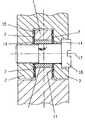
제1도는 2개의 부분으로 구성된 케이싱과 성형된 스프링 탄성요소가 달린 안경힌지 조절구(regulator)를 도시한 도면.1 shows a spectacle hinge regulator with a casing consisting of two parts and a molded spring resilient element.
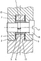
제2도는 3개의 부분으로 구성된 케이싱이 달린 안경힌지 조절구를 도시한 도면.2 shows a spectacle hinge control with a casing consisting of three parts.
제3도 및 제4도는 단일의 힌지 플랜지내에 파묻힘이 없이 지지링과 천공된 판스프링 요소에 의하여 선회범위가 조절되는 안경힌지(eyeglass hinge)조절구를 도시한 도면.3 and 4 show eyeglass hinge controls whose pivoting range is controlled by support rings and perforated leaf spring elements without being embedded in a single hinge flange.
제5도는 지지링이 달린 판스프링의 정면도.5 is a front view of a leaf spring with a support ring.
제6도는 지지링이 달린 판스프링의 단면도.6 is a cross-sectional view of a leaf spring with a support ring.
제7도는 지지링과 케이싱이 달려있고, 선반과 천공 기를 이용하여 제작한 판스프링의 단면도.7 is a cross-sectional view of a leaf spring made using a lathe and a perforator with a support ring and a casing.
제8도는 선반으로 제작한 케이싱부재에 천공에 의하여 제작된 지지링이 달린 판스프링을 용접 시킨 부재의 단면도.8 is a cross-sectional view of a member in which a plate spring with a support ring made by drilling is welded to a casing member made of a lathe.
제9도는 조절하는 안경힌지 조절구를 도시한 도면.Figure 9 is a view showing a hinge hinge adjustment glasses.
제10도는 스프링 탄성요소로서의 파형스프링으로 선회범위를 조절하는 안경힌지 조절구를 도시한 도면.10 is a view showing a hinge hinge for adjusting the swing range of the spring as a spring elastic element.
제11도는 제9도에 도시한 안경힌지로서 O-링이 추가로 제공되어 있는 안경힌지의 변형을 도시한 도면.FIG. 11 shows a variant of the spectacle hinge further provided with an O-ring as the spectacle hinge shown in FIG.
* 도면의 주요부분에 대한 부호의 설명* Explanation of symbols for main parts of the drawings
1 : 힌지 플랜지 5, 6 : 케이싱 부분1: hinge
7 : 스프링탄성요소 11 : 부착면7 spring
14 : 링 15 : 지지링14
16 : 힌지나사 17 : 힌지나사축16: Hinge Screw 17: Hinge Screw Shaft
18 : O-링18: O-ring
본 발명은 힌지(hinge), 특히 적어도 2개의 힌지 플랜지와 1개의 힌지나사가 달린 3개 부분으로 된 안경힌지의 선회범위를 조절하는 것으로서, 힌지 플랜지의 힌지 눈구멍(hinge eye)내에 힌지나사를 에워싸는 고정케이싱이 배치 되어 있고, 이 케이싱은 힌지 플랜지 위로 돌기하여 있고, 인접한 힌지 플랜지에 함께 선회할 수 있게 접속되어 있으며, 적어도 하나의 힌지 플랜지의 힌지축에 대하여 회전 대칭적인 부착면에 앞으로 당겨져 접속되어 있는 적어도 하나의 요소가 존재하는 힌지의 선회범위 조절구에 관한 것이다.The invention adjusts the turning range of a hinge, in particular a three-piece spectacle hinge with at least two hinge flanges and one hinge screw, for enclosing the hinge screw in the hinge eye of the hinge flange. A fixed casing is arranged, which casing protrudes over the hinge flange, is connected so as to pivot together to an adjacent hinge flange, and is pulled forward to a rotationally symmetrical attachment surface with respect to the hinge axis of at least one hinge flange. It relates to a swing range control of a hinge in which at least one element is present.
서로 맞물려 있는 힌지 플랜지가 달린 안경태용의 힌지는 이미 공지된 것으로서, 이러한 힌지의 천공내에는 케이싱에 의하여 둘러싸이는 힌지나사가 배치되어 있다(DE-PS 1 117 911). 이 케이싱은 플라스틱재료로 구성되어 있다. 케이싱의 길이는 힌지 플랜지의 해당천공의 전체길이보다 더 길다. 안경힌지를 나사로 죄어 맞출 때, 케이싱은 나사머리의 하측면과 힌지 플랜지의 전면 사이에 눌리게 된다. 이로 인하여 어느 정도의 마찰이 생기게 된다.Hinges for eyeglasses with hinged flanges interlocked with each other are already known, and hinge screws surrounded by a casing are arranged in the perforations of these hinges (DE-PS 1 117 911). This casing is made of plastic material. The length of the casing is longer than the total length of the corresponding perforation of the hinge flange. When the eyeglass hinge is screwed in, the casing is pressed between the lower side of the screw head and the front face of the hinge flange. This causes some friction.
케이싱 힌지나사 머리에 접속되어 있기 때문에, 힌지에 고정된 부분이 회전운동을 할 때 힌지의 결합이 느슨하여질 수 있다. 반씩으로 나누어진 힌지들 사이의 제동모멘트는 본질적으로 힌지나사의 죄임 모멘트에 따라 달라지기 때문에, 이러한 죄임 모멘트가 너무 큰 때에는 힌지가 차단 되어 움직이지 아니하게 된다. 일정한 사용기간이 경과 하였거나, 죄임 모멘트가 너무 적은 때에도, 힌지에 고정된 안경다리가 중력의 작용으로 인하여 낙하되는 것을 방지할 정도로 제동모멘트가 더 이상 충분하지 아니하다.Since it is connected to the casing hinge screw head, the engagement of the hinge can be loosened when the portion fixed to the hinge makes a rotary motion. Since the braking moment between the hinges divided in half depends essentially on the clamping moment of the hinge screw, the hinge is blocked when it is too large and does not move. Even when a certain period of use has elapsed or when the clamping moment is too small, the braking moment is no longer sufficient to prevent the hinged eyeglasses from falling due to the action of gravity.
안경힌지는 DE-OS 2 039 455 에 의하여서도 공지되어 있는데, 여기에서는 축방향으로 절개되고, 예정된 장선이 제공되어 있는 케이싱이 힌지 플랜지내에 들어 있다. 힌지 플랜지 위로 돌출하여 있는 케이싱의 전면은 인접한 힌지 플랜지의 전면에 힘폐쇄적으로 접속되어 있다. 이때 힌지의 마찰모멘트는 나사의 죄임모멘트에 따라 달라진다. 마찰 모멘트는 방사상 방향으로 접속된 케이싱에 의하여 정하여 진다. 이러한 공지된 힌지에 있어서도, 어느 정도의 사용 기간이 경과한 후에는 케이싱이 방사상 방향으로 더 이상 움직일 수 없기 때문에, 힌지나사가 죄어들어가자 마자(힌지나사를 조정하면 케이싱이 축방향으로 당겨진다) 안경다리가 낙하된다. 즉 제동모멘트가 경감된다.The spectacle hinge is also known from DE-OS 2 039 455, in which a casing with an axial incision and a predetermined joist is provided in the hinge flange. The front face of the casing protruding above the hinge flange is forcefully connected to the front face of the adjacent hinge flange. The friction moment of the hinge depends on the tightening moment of the screw. The friction moment is determined by the casing connected in the radial direction. Even with this known hinge, the casing can no longer move in the radial direction after a certain period of use, so as soon as the hinge screw is tightened (adjusting the hinge screw pulls the casing in the axial direction). The glasses legs fall down. In other words, the braking moment is reduced.
US-PS 1 867 346에 의하여 창문, 출입문등에 제공되어 있고, 축방향으로 신축되는 스프링 요소가 달려있는 선회범위를 조절하는 힌지도 공지되어 있다. 여기에서도 힌지의 마찰모멘트는 나사의 죄임모멘트와는 상관이 없으나 나사를 죄어붙이는 힘이 외측힌지플랜지에 의하여 지지되어야 하며, 이에 따라 힌지 플랜지는 그만큼 단단하여야 한다.Hinges are provided for windows, doors, etc., according to US-PS 1 867 346, which adjust the turning range in which the spring elements are axially stretched. Here, the frictional moment of the hinge is not related to the clamping moment of the screw, but the force for tightening the screw must be supported by the outer hinge flange, so that the hinge flange must be so tight.
그 외에도, DE-OS 28 28 908에 의하여 힌지 눈구멍 사이에 칼러 케이싱이 달린 작은 플라스틱판들이 끼워져 있는 힌지가 공지되어 있다. 칼러 케이싱은 플라스틱판과 접촉하게 하거나, 이와 일체로 형성할 수 있다. 선회범위는 나사를 축방향으로 죄어붙임으로써 조절할 수 있다. 그러나, 여기에 있어서도 제동면의 접촉점은 힌지나사의 죄임모멘트에 따라 달라진다. 그 외에도, 칼러 케이싱과 외측힌지 플랜지 사이의 상대운동이 행하여져야 한다.In addition, a hinge is known by DE-OS 28 28 908 in which small plastic plates with color casings are fitted between the hinge eye holes. The color casing may be in contact with or formed integrally with the plastic plate. The turning range can be adjusted by tightening the screw in the axial direction. However, also here, the contact point of the braking surface depends on the tightening moment of the hinge screw. In addition, relative movement between the color casing and the outer hinge flange must be performed.
본 발명은 전술한 종류의 힌지로서, 힌지의 마찰모멘트가 나사의 죄임모멘트에 의존되지 아니하고, 힌지의 선회범위를 정하는 제동모멘트가 장시간이 경과하면서도 항시 일정한 힌지를 제공하는 것을 그 과제로 한다.The present invention provides a hinge of the above-described type, wherein the frictional moment of the hinge does not depend on the clamping moment of the screw, and the braking moment defining the swing range of the hinge always provides a constant hinge over a long time.
이러한 과제는 본 발명에 의하여 상기요소를 스프링 모양으로 탄력있게 하고, 이와 같은 요소를 케이싱이 그 안에 배치되어 있는 힌지 플랜지와 이러한 힌지 플랜지에 대하여 상대적으로 움직일 수 있는 인접된 힌지 플랜지 사이에 배치하고, 힌지나사축에 대하여 축방향으로 접촉면에 신축성있게 접속시킴으로써 해결한다.This task makes the element resilient to a spring shape according to the present invention, such an element being disposed between a hinge flange with a casing disposed therein and an adjacent hinge flange which is movable relative to this hinge flange, This is solved by flexibly connecting the contact surface in the axial direction with respect to the hinge screw shaft.
본 발명에 있어서, 하나의 힌지 플랜지내에는 힌지나사가 죄어들어가도록 인접한 힌지 플랜지 또는 힌지나사 쪽으로 움직이지 아니하는 고정케이싱이 있다. 이러한 케이싱에 의하여, 힌지나사의 죄임모멘트와 관계없이, 케이싱이 접속 되는 요소들 사이의 일정간격이 확정된다. 케이싱이 그 안에 배치되어 있는 힌지 플랜지와 이러한 힌지플랜지에 상대적으로 움직이는 인접한 힌지 플랜지 사이에는 하나의 스프링 탄성요소가 배치되어 있고, 이러한 탄성요소는 본질적으로 방사성 방향에 따라 뻗어있고, 힌지나사와 반대 방향에 있는 케이싱측면상에 있다.In the present invention, there is a fixed casing in one hinge flange which does not move toward the adjacent hinge flange or the hinge screw so that the hinge screw is tightened. By this casing, a certain distance between the elements to which the casing is connected is determined irrespective of the tightening moment of the hinge screw. A spring elastic element is disposed between the hinge flange in which the casing is disposed and the adjacent hinge flange moving relative to this hinge flange, which elastic element extends essentially in the radial direction and is opposite to the hinge screw. On the side of the casing.
스프링탄성요소는 부착면과 예를 들면, 인접한 힌지 플랜지에 접속되어 있는 케이싱단부 높이 사이에 축방향으로 뻗어있는 공간내에 배치되어 있다. 이러한 공간의 높이는 스프링 탄성요소가 축방향으로 움직일 수 있고, 힌지나사 또는 인접한 힌지 플랜지가 스프링 탄성요소에 어떠한 작용을 미치지 못하도록 정한다. 따라서 스프링탄성요소가 힌지 플랜지에 가하는 제동모멘트는 이 탄성요소를 부착면에 접속시키는 장력에만 의존된다. 힌지나사가 약한 또는 강한 죄임모멘트로 장착 되어 있는가의 여부에 관계없이, 힌지나사를 죄이자마자 일정한 제동모멘트가 생긴다. 종래의 기술과는 달리 케이싱이 인접한 힌지 플랜지에 접속되어 있는 평면은 너무 높은 평면압력으로 인하여 가소성 변형이 생기지 아니하도록 그 크기를 정할 수 있다.The spring elastic element is arranged in a space extending axially between the attachment surface and, for example, the height of the casing end connected to the adjacent hinge flange. The height of this space is such that the spring elastic element can move in the axial direction and the hinge screw or adjacent hinge flanges have no effect on the spring elastic element. The braking moment that the spring elastic element exerts on the hinge flange depends only on the tension connecting this elastic element to the attachment surface. Regardless of whether the hinge screw is mounted with a weak or strong clamping moment, a constant braking moment occurs as soon as the hinge screw is tightened. Unlike the prior art, the plane in which the casing is connected to the adjacent hinge flange can be sized so that plastic deformation does not occur due to too high plane pressure.
너무 큰 조임모멘트로 인한 힌지의 폐색이 배제된다. 제동모멘트와 이에 의한 힌지의 선회범위는 상당한 시간이 경과하더라도 일정하게 유지된다.Occlusion of the hinge due to too large tightening moment is excluded. The braking moment and therefore the swing range of the hinge remain constant over considerable time.
본 발명의 적당한 실시예에 있어서, 스프링탄성요소는 힌지 플랜지에 맞대어 회전하지 못하게 고정배치되어 있고, 또 다른 힌지 플랜지의 부착면에 인장된 상태로 접속되어 있다.In a suitable embodiment of the invention, the spring-elastic element is fixedly arranged so as not to rotate against the hinge flange and is connected in tension to the attachment surface of another hinge flange.
스프링탄성요소가 접속되어 있는 부착면은 힌지나사축에 대하여 평행으로 뻗어있는 것이 아니라, 이에 대하여 일정한 각을 이루고 있다. 본 발명의 적당한 실시예에 있어서, 부착면은 힌지나사측에 대하여 거의 수직으로 뻗어 있다.The attachment surface to which the spring elastic element is connected does not extend in parallel with the hinge screw axis, but has a constant angle thereto. In a suitable embodiment of the present invention, the attachment surface extends substantially perpendicular to the hinge screw side.
모든 경우에 있어서, 스프링탄성요소는 본질적으로 축 방향에 따라 부착면상에 작용한다.In all cases, the spring elastic element acts essentially on the attachment surface along the axial direction.
특허청구범위 제6항에 기술된 매우 적당한 실시예에 있어서, 스프링탄성요소는 회전할 수 없게 케이싱에 고정 배치되어 있고, 특히 케이싱과 고정결합되어 있다. 이에 의하여 스프링탄성요소는 언제나 부착면의 동일부분내에서 부착면에 접속되어 있다.In a very suitable embodiment as claimed in
특허청구범위 제7항에 기술된 본 발명의 또다른 실시예에 있어서, 케이싱에는 2개의 스프링탄성요소가 제공되어 있다. 이 실시예에 있어서는 압력과 이에 의한 제동 모멘트가 힌지 플랜지의 각 전면내에 있는 부착면을 거쳐 힌지 플랜지상에 가하여진다.In another embodiment of the invention described in
특허청구범위 제8항 및 제9항에서는 본 발명의 또다른 적당한 실시예로써 스프링 탄성요소가 케이싱에 성형되어 있는 것과 케이싱에 두개의 스프링 탄성요소가 제공되어 있고, 케이싱이 내장되어 있는 힌지 플랜지의 각 전면에 부착면이 제공되어 있고, 각 부착면에 스프링 탄성요소가 접속되어 있는 것을 기술하였다.
본 발명의 또다른 적당한 실시예에 있어서, 스페이서로서 작용하는 케이싱이 일부재로 제조되어 있지 아니하고, 케이싱이 몸체와 스프링탄성요소가 이에 성형되어 있거나 이와 결합되어 있는 링으로 구성되어 있다.In another suitable embodiment of the present invention, the casing acting as a spacer is not made of some material, but the casing consists of a ring in which the body and the spring elastic element are molded or bonded thereto.
본 발명의 또다른 적당한 실시예에 있어서, 케이싱이 힌지나사에 성형되어 하나의 원통형 부가물을 형성할 수 있다.In another suitable embodiment of the present invention, the casing may be molded to the hinge screw to form one cylindrical adjunct.
스프링탄성요소는 전술한 바와 같이 적어도 하나의 부착면에 접속되어 있고, 해당힌지플랜지를 제동시킨다. 본 발명의 적당한 실시예에 있어서는 이러한 목적을 위하여 케이싱이 내장되어 있는 힌지 플랜지내에 하나의 침강부가 제공되어 있다. 이 경우에는 침강부의 저면이 부착면으로 이용된다. 그러나, 이와 같은 침강부는 부분적으로 그 일부는 케이싱이 내장되어 있는 힌지 플랜지내에, 다른 일부는 인접된 힌지플랜지내에 제공하거나, 그 전체를 인접된 힌지 플랜지내에 제공할 수 있다.The spring elastic element is connected to at least one attachment surface as described above, and brakes the hinge flange. In a suitable embodiment of the present invention, for this purpose, a single recess is provided in the hinge flange in which the casing is incorporated. In this case, the bottom of the settling portion is used as the attachment surface. However, such settlings may be provided, in part, within a hinge flange in which the casing is embedded, in another part in an adjacent hinge flange, or in its entirety in an adjacent hinge flange.
위에서 말한 마지막 경우에 있어서는 케이싱이 내장되어 있는 힌지 플랜지의 전면이 부착면으로서 이용된다.In the last case mentioned above, the front face of the hinge flange in which the casing is incorporated is used as the attachment surface.
특허청구범위 제13항에서는 본 발명의 또다른 적당한 실시예로서 스프링 탄성요소가 지지링에 의하여 둘러싸여 있고 그 외경이 중간힌지 플랜지의 외경과 거의 동일하고 중간힌지 플랜지의 높이가 지지링의 높이보다 더 높고, 케이싱이 길이보다 더 작은 것을 기술하였다. 특허청구범위 제16항에 기술되어 있는 판스프링부분에는 스프링의 전체적인 동작범위가 클 때 서서히 상승하여 그 공차를 지각할 수 없는 탄력이 점증된다.According to
본 발명에 의한 힌지의 선회범위조절에 관한 실시예를 첨부도면에 의하여 설명하면 다음과 같다. 모든 실시예에 있어서는 3개의 부분으로 구성된 안경힌지 또는 그 일부를 도시하였다. 도면상 서로 동일한 부분은 동일한 참조부호를 붙였다.Referring to the accompanying drawings, the embodiment of the swing range adjustment of the hinge according to the present invention. In all the examples, a three-piece spectacle hinge or part thereof is shown. The same parts in the drawings are given the same reference numerals.
제1도에 도시한 안경힌지는 통상적으로 안경다리가 고정되어 있는 하나의 힌지 플랜지(1)와 통상적으로 안경(도시되지 않음)중간부재와 결합되어 있는 2개의 인접된 힌지 플랜지(2,3) 및 하나의 힌지나사(16)로 구성되어 있다. 그러나 안경중간부재도 중간힌지 플랜지에 고정시키고, 안경 다리는 인접된 2개의 힌지 플랜지에 고정시킬 수 있다. 중간힌지 플랜지(1)의 힌지 눈구멍(hinge eye)내에는 제1도에 있어서 2개의 부분(5,6)으로 구성되어 있는 케이싱이 내장되어 있다. 케이싱 부분(5,6)은 서로 접속되어 있고, 중간힌지 플랜지 위로 솟아 있다. 즉, 케이싱의 힌지나사축 방향으로의 길이가 중간힌지 플랜지(1)의 높이보다 약간 더 길다. 케이싱의 전면은 인접된 힌지 플랜지(2,3)의 내측 전면(12,13)에 접속되어 있다.The spectacle hinge shown in FIG. 1 typically has one
나사 쪽으로 향한 케이싱의 외표면에는 케이싱의 전면 부분내에 2개의 스프링 탄성요소(7)가 성형되어 있다. 스프링 탄성요소(7)가 달린 케이싱부분(5) 또는 스프링 탄성요소(7)가 달린 케이싱부분(6)은 선반에 의하여 제조 한다.On the outer surface of the casing towards the screw, two spring
스프링탄성요소(7)는 중간힌지 플랜지의 전면부분 내에 있는 각 부착면(11)마다에 인장접속되어 있다. 이 실시예에 있어서, 부착면(11)은 힌지나사측(17)에 대하여 수직으로 배치되어 있다. 그 외에도, 부착면(11)은 이 축에 대하여 회전대칭적으로 되어 있다.The spring
각 스프링탄성요소(7)는 방사상 방향에 따라 중간힌지 플랜지(1)의 침강부내로 뻗어 있다. 이 침강부는 축방향으로는 부착면으로 이용되는 저면과 인접된 힌지 플랜지에 접속되어 있는 케이싱단부(전면)의 높이사이로 뻗어 있다. 이러한 스프링 탄성요소의 침강부 크기는 스프링 탄성요소가 축방향으로 움직일 수 있을 정도로 한다. 전술한 힌지를 조립하려면, 먼저 스프링탄성요소가 달린 케이싱(5,6)을 중간힌지플랜지내에 집어넣고, 이어서 이 케이싱 들을 2개의 부분으로 구성된 힌지부재내에 집어넣는다. 나사(16)는 힌지의 눈구멍(hinge eye) 또는 케이싱을 통하여 안내되고, 힌지 플랜지(2)내에 죄어붙여진다. 그 부분으로 구성된 힌지부재(2,3)는 스페이서로서 작용하는 케이싱(5,6) 때문에, 스프링탄성요소에 의하여 가하여지는 제동모멘트에 영향을 주지 아니하도록 나사(16)에 의하여 블록상에 장착시킬 수 있다.Each spring
제2도는 3개의 부분으로 되어 있는 스펜서가 달린 안경힌지를 도시한 것이다. 케이싱 몸체(4)의 양전면에는 스프링 탄성요소가 성형되어 있는 링(14)으로 구성된 판 스프링이 접속되어 있다. 링(14)은 케이싱몸체(4)와 인접된 힌지 플랜지(2,3)의 전면사이에 배치되어 있다. 판스프링은 힌지나사를 죄어붙임으로써 그 부분으로된 힌지부재(2,3)와 회전할 수 없게 고정결합된다. 판스프링은 단일 힌지 플랜지의 침강부내에서 링면에 의하여 제동된다.Figure 2 shows a spectacle hinge with a spencer in three parts. On both positive surfaces of the
제3도는 단일힌지 플랜지내에 침강부 없이 선회범위를 조절하는 안경힌지를 도시한 것이다. 이 실시예는 간단히 제조할 수 있고, 경우에 따라서는 하나의 케이싱 몸체(4)와 2개의 판스프링이 제공된다. 제5도 및 제6도에 도시한 바와 같이, 각 판스프링은 판스프링에 성형되어 있는 지지링(15)에 의하여 둘러싸여 있다. 이러한 지지링의 외경(d 1)은 중간힌지 플랜지(1)의 외경과 거의 같다. 중간힌지 플랜지(1)의 높이(h 1)는 지지링(15)의 이중높이(h 2) 보다는 높고, 케이싱(케이싱몸체(4)와 2개의 링(14)으로 구성 되어 있는)의 길이(h 3)보다 작다. 지지링(15)은 힌지가 경사면에 맞대어 안정되게 머물러 있도록 작용한다.3 shows a spectacle hinge which adjusts the turning range without settling in the single hinge flange. This embodiment can be manufactured simply, in which case one
제4도는 제3도와 유사한 변형을 도시한 것이다. 그러나, 여기에서는 조립을 용이하게 하기 위하여 케이싱이 2개의 부분으로 형성되어 있고, 각 케이싱 부재(5,6)에는 판스프링(7)이 단접되어 있다(제8도 참조).4 shows a variation similar to that of FIG. However, in order to facilitate assembly, the casing is formed of two parts, and the
제9도는 선회범위를 조절하는 안경힌지로서, 케이싱에 스프링탄성요소만이 제공되어 있는 안경힌지를 도시한 것이다. 스페이서로서 작용하는 케이싱과 스프링탄성요소는 일체로 만들어져 있다. 이 실시예는 일면실시와 이에 의한 일체형성이 가능하기 때문에, 조립이 매우 간단하다. 그 외에도, 이러한 일면실시는 단면이 동일하게 감소될 때 필요한 경우에는 침강부의 크기를 2배로 증대시킴으로써 압력을 이면실시의 경우보다 더 크게 할 수 있는 가능성을 제공한다. 중간힌지 눈구멍 중 침강되지 아니하고, 스프링에 의하여 외측힌지 눈구멍에 맞대어 눌리지 아니하는 측면은 그 직경 부분에 걸쳐 평면으로 놓여 있다. 따라서, 이 실시예는 매우 안정되고, 마모가 적으며, 허용오차도 매우 적다.9 shows a spectacle hinge for adjusting the swing range, in which only a spring elastic element is provided on the casing. The casing and the spring elastic element, which act as spacers, are made integral. Since this embodiment can be integrated with the one-sided embodiment, the assembly is very simple. In addition, this one-sided implementation offers the possibility of increasing the pressure larger than that of the back-side implementation by doubling the size of the settling section if necessary when the cross section is equally reduced. The side which is not settled in the middle hinge eye hole and which is not pressed against the outer hinge eye hole by the spring lies in a plane over its diameter portion. Therefore, this embodiment is very stable, has low wear, and very little tolerance.
요약하면, 힌지, 특히 안경힌지의 전술한 선회범위조절은 안경의 수명이 다하는 날까지 유역이 없는(clearance free)안경힌지의 선회범위를 제공하고, 마찰부위의 부식과 관절경합의 폐색도 없을 뿐 아니라, 안경다리가 가볍게 선회하는 일도 일어나지 아니한다는 것을 확인할 수 있다. 선회범위의 조절에는 언제나 동일한 운동저항이 제공된다.In summary, the above-mentioned turning range adjustment of the hinges, especially the spectacle hinges, provides a range of swing-free eyeglass hinges until the end of the life of the glasses, and there is no corrosion of the friction areas and no obstruction of joint competition. In addition, it can be seen that the light turning of the glasses does not occur. The same range of motion is always provided for adjustment of the turning range.
Claims (9)
Applications Claiming Priority (3)
| Application Number | Priority Date | Filing Date | Title |
|---|---|---|---|
| DE3727706 | 1987-08-19 | ||
| DEP3727706.5 | 1987-08-19 | ||
| DE19873727706 DE3727706A1 (en) | 1987-08-19 | 1987-08-19 | GEAR ADJUSTMENT FOR HINGES |
Publications (2)
| Publication Number | Publication Date |
|---|---|
| KR890004189A KR890004189A (en) | 1989-04-20 |
| KR920008004B1 true KR920008004B1 (en) | 1992-09-21 |
Family
ID=6334089
Family Applications (1)
| Application Number | Title | Priority Date | Filing Date |
|---|---|---|---|
| KR1019880009788A KR920008004B1 (en) | 1987-08-19 | 1988-08-01 | Hinge motion regulator for eyeglasses |
Country Status (7)
| Country | Link |
|---|---|
| US (1) | US4951349A (en) |
| JP (1) | JPH01239280A (en) |
| KR (1) | KR920008004B1 (en) |
| AT (1) | AT397730B (en) |
| DE (1) | DE3727706A1 (en) |
| FR (1) | FR2623554B1 (en) |
| IT (1) | IT1224874B (en) |
Families Citing this family (41)
| Publication number | Priority date | Publication date | Assignee | Title |
|---|---|---|---|---|
| US5146805A (en) * | 1991-09-12 | 1992-09-15 | General Motors Corporation | Bushing assembly for a pivot connection |
| JP2504713B2 (en) * | 1993-03-09 | 1996-06-05 | タキゲン製造株式会社 | Lock handle device for drawer revolving door |
| JP2504714B2 (en) * | 1993-04-07 | 1996-06-05 | タキゲン製造株式会社 | Lock handle device for drawer revolving door |
| DE9400456U1 (en) * | 1994-01-13 | 1994-04-28 | Kittiworakun Chokechai | Glasses hinge |
| DE4420844A1 (en) * | 1994-06-15 | 1995-12-21 | Porsche Ag | Articulated connection of two adjacent components, especially a convertible top |
| IT1281524B1 (en) * | 1995-12-12 | 1998-02-18 | Franco Dioguardi | HINGE FOR AUTOMATIC MECHANICAL CLOSURE OF THE GLASS STEM |
| FR2751431B1 (en) * | 1996-07-18 | 1998-09-04 | Sporoptic Pouilloux Sa | GLASSES WITH PIVOTING BRANCHES |
| US5826307A (en) * | 1997-06-17 | 1998-10-27 | Chin-Fu; Horng | Rotating spindle mechanism |
| JP2975361B1 (en) * | 1998-11-10 | 1999-11-10 | 株式会社タケダ企画 | Spring hinge for glasses |
| DE50002003D1 (en) * | 1999-09-24 | 2003-06-05 | Silhouette Internat Schmied Gm | HINGE JOINT FOR GLASSES |
| FR2808598B1 (en) * | 2000-05-05 | 2002-08-02 | Abc Lunettes | EYEWEAR MOUNT WITH ARTICULATED BRANCHES |
| US6332682B1 (en) * | 2000-09-29 | 2001-12-25 | Yoshida Industry Co., Ltd. | Hinge structure for use in joining temple and front rim in eyeglasses |
| DE10222898A1 (en) * | 2001-06-11 | 2002-12-19 | Klingelhoefer Jost | Door hinge for vehicle door has integrated brake and comprises separate bush lining bore in hinge eye and having stepped decreasing diameter |
| DE10151644A1 (en) * | 2001-10-11 | 2003-05-15 | Obe Ohnmacht & Baumgaertner | glasses hinge |
| PT1552169E (en) * | 2002-06-24 | 2008-06-26 | Ergonomic Solutions Internat L | A rotatable link |
| DE10255780A1 (en) * | 2002-11-28 | 2004-06-17 | Rodenstock Gmbh | Joint for an eyeglass frame |
| DE102004017391A1 (en) * | 2004-04-08 | 2005-10-27 | Wilhelm Karmann Gmbh | Bushing and articulated connection with such a socket |
| CN2804891Y (en) * | 2005-03-22 | 2006-08-09 | 深圳市龙岗区横岗镇高雅眼镜厂 | Spectacles clutch spring hinge |
| US7959168B2 (en) * | 2006-04-04 | 2011-06-14 | Magna International Inc. | Suspension link with integral pivot assembly |
| DE102007023329A1 (en) * | 2007-05-16 | 2008-11-20 | Ims Gear Gmbh | Transmission for an adjusting device, in particular a motor vehicle adjusting device, with clearance compensation |
| ITBO20090758A1 (en) * | 2009-11-20 | 2011-05-21 | Drei S N C Di Drei Silvio & C | FIXING GROUP |
| USD666228S1 (en) * | 2011-03-16 | 2012-08-28 | Satisloh North America, Inc. | Optic device securing structure |
| USD666231S1 (en) | 2011-03-16 | 2012-08-28 | Satisloh North America, Inc. | Optic device securing structure |
| USD666229S1 (en) * | 2011-03-16 | 2012-08-28 | Satisloh North America, Inc. | Optic device securing structure |
| US9308617B2 (en) | 2011-03-16 | 2016-04-12 | Satisloh North America, Inc. | Securing structure for optic device |
| USD666230S1 (en) | 2011-03-16 | 2012-08-28 | Satisloh North America, Inc. | Optic device securing structure |
| US8978201B2 (en) * | 2013-08-08 | 2015-03-17 | Delphi Technologies, Inc. | Anti-rattle sleeve for a hinge joint |
| WO2016066583A1 (en) * | 2014-10-30 | 2016-05-06 | SAFILO SOCIETÀ AZIONARIA FABBRICA ITALIANA LAVORAZIONE OCCHIALI S.p.A. | A hinge device for connecting the sides to the fronts of spectacle frames, and spectacles including this device |
| US9404300B1 (en) * | 2015-04-28 | 2016-08-02 | Wayne W. Ramsdell | Hinge and applications thereof |
| US10428565B1 (en) | 2015-04-28 | 2019-10-01 | Wayne W. Ramsdell | Hinge and applications thereof |
| US11530560B1 (en) | 2015-04-28 | 2022-12-20 | Wayne W. Ramsdell | Hinge and applications thereof |
| US9828795B1 (en) | 2015-04-28 | 2017-11-28 | Wayne W. Ramsdell | Hinge and applications thereof |
| US9574384B1 (en) * | 2015-09-23 | 2017-02-21 | Michael J. Reischmann | Infinitely variable angle connecting system |
| CN105221560B (en) * | 2015-10-13 | 2018-05-08 | 重庆晟初科技有限公司 | A kind of connecting joint |
| CN106801701B (en) * | 2016-03-01 | 2019-04-12 | 江苏泰来包装工程集团有限公司 | A kind of macropore coaming plate hinge |
| CN106812784B (en) * | 2016-03-01 | 2019-03-12 | 江苏泰来包装工程集团有限公司 | A kind of manufacturing technology of intensive sword tooth coaming plate hinge |
| CN106812785B (en) * | 2016-03-01 | 2019-03-15 | 江苏泰来包装工程集团有限公司 | A kind of manufacturing technology of double bidentate coaming plate hinge |
| CN106964111A (en) * | 2017-05-11 | 2017-07-21 | 杭州厚谋创意设计有限公司 | A kind of word horse traction of leg one, which is stretched, uses toughness trainer |
| CN106975202A (en) * | 2017-05-11 | 2017-07-25 | 杭州厚谋创意设计有限公司 | A kind of word horse traction of leg one stretches the back seat plate with toughness trainer |
| JP6946127B2 (en) * | 2017-09-19 | 2021-10-06 | 株式会社シマノ | Electric reel backup system |
| DE102021126260B4 (en) | 2020-10-14 | 2023-04-06 | Eschenbach Optik Gmbh | glasses frame |
Family Cites Families (12)
| Publication number | Priority date | Publication date | Assignee | Title |
|---|---|---|---|---|
| US1867346A (en) * | 1927-09-19 | 1932-07-12 | Nat Mfg Co | Friction hinge |
| GB423641A (en) * | 1933-04-05 | 1935-02-05 | Paul Hempel | Improvements in or relating to spectacle frames |
| US2288657A (en) * | 1940-01-04 | 1942-07-07 | American Optical Corp | Ophthalmic mounting |
| US2381011A (en) * | 1941-02-07 | 1945-08-07 | American Optical Corp | Ophthalmic mounting |
| US2412120A (en) * | 1945-06-28 | 1946-12-03 | Bausch & Lomb | Spectacle temple connection |
| US2567879A (en) * | 1949-09-23 | 1951-09-11 | Thomas J Fox | Spectacle frame hinge |
| US4018104A (en) * | 1975-03-17 | 1977-04-19 | Caterpillar Tractor Co. | Frictionally held control linkage for engine throttle controls and the like |
| DE2828908C2 (en) * | 1978-06-30 | 1983-10-27 | OBE-Werk Ohnmacht & Baumgärtner GmbH & Co KG, 7536 Ispringen | Hinge for glasses with speed regulation |
| IT1160626B (en) * | 1977-09-22 | 1987-03-11 | Obe Werk Kg | HINGE FOR GLASSES WITH ADJUSTMENT OF MOVEMENT |
| US4491436A (en) * | 1983-03-21 | 1985-01-01 | Deere & Company | Pivot pin assembly |
| SE453846B (en) * | 1983-09-19 | 1988-03-07 | Scharwaechter Gmbh Co Kg | DORRGANGERNER FOR MOTOR VEHICLE |
| US5120791A (en) * | 1990-07-27 | 1992-06-09 | Lisco, Inc. | Golf ball cover compositions |
-
1987
- 1987-08-19 DE DE19873727706 patent/DE3727706A1/en active Granted
-
1988
- 1988-07-15 AT AT0182888A patent/AT397730B/en not_active IP Right Cessation
- 1988-08-01 KR KR1019880009788A patent/KR920008004B1/en active IP Right Grant
- 1988-08-05 IT IT8848273A patent/IT1224874B/en active
- 1988-08-09 JP JP63198764A patent/JPH01239280A/en active Pending
- 1988-08-18 FR FR888811003A patent/FR2623554B1/en not_active Expired - Fee Related
- 1988-08-19 US US07/233,802 patent/US4951349A/en not_active Expired - Fee Related
Also Published As
| Publication number | Publication date |
|---|---|
| JPH01239280A (en) | 1989-09-25 |
| DE3727706A1 (en) | 1989-03-02 |
| KR890004189A (en) | 1989-04-20 |
| IT1224874B (en) | 1990-10-24 |
| IT8848273A0 (en) | 1988-08-05 |
| FR2623554B1 (en) | 1992-02-21 |
| US4951349A (en) | 1990-08-28 |
| FR2623554A1 (en) | 1989-05-26 |
| AT397730B (en) | 1994-06-27 |
| ATA182888A (en) | 1993-10-15 |
| DE3727706C2 (en) | 1989-07-20 |
Similar Documents
| Publication | Publication Date | Title |
|---|---|---|
| KR920008004B1 (en) | Hinge motion regulator for eyeglasses | |
| US5079799A (en) | Friction hinge assembly | |
| US6053610A (en) | Actuation mechanism for variable focal length spectacles | |
| KR980004600A (en) | Tilt-Adjustable Disc Player | |
| US5657511A (en) | Piston-tpye door closer with adjustable closing speeds | |
| US6654985B1 (en) | Pivot hinge | |
| KR980004672A (en) | Disc player with adjustable phase and tilt | |
| US5589895A (en) | Hinge structure of a spectacle frame | |
| US5267759A (en) | Connector assembly | |
| GB2333079A (en) | Rack and pinion assembly | |
| KR20040030600A (en) | An eyeglass frame, a hinge, an eyeglass and a method of manufacturing a hinge | |
| JPH09325303A (en) | Spectacle frame | |
| EP0235780A2 (en) | Hinge device, particularly for spectacle frames | |
| KR100390412B1 (en) | hinge-assembly | |
| US6811266B2 (en) | Support structure for projector | |
| KR100330065B1 (en) | Hinge assembly of L.C.D monitor | |
| US5042914A (en) | Lens focusing mechanism | |
| JPH1096843A (en) | Structure for holding optical device | |
| KR200184244Y1 (en) | Disk type friction hinge device | |
| ES2030895T3 (en) | ELASTIC HINGE FOR GLASSES FRAME. | |
| JPS64586Y2 (en) | ||
| JPH02266311A (en) | Lens driver | |
| KR100383730B1 (en) | Clip type friction hinge devices | |
| EE04285B1 (en) | Window, door or furniture hinge mounting pins mounting element | |
| KR910001111Y1 (en) | A hinge in door |
Legal Events
| Date | Code | Title | Description |
|---|---|---|---|
| A201 | Request for examination | ||
| E902 | Notification of reason for refusal | ||
| G160 | Decision to publish patent application | ||
| E701 | Decision to grant or registration of patent right | ||
| NORF | Unpaid initial registration fee |