KR920006962B1 - Platen arrangement for hot melt ink jet apparatus - Google Patents
Platen arrangement for hot melt ink jet apparatus Download PDFInfo
- Publication number
- KR920006962B1 KR920006962B1 KR1019890700815A KR890700815A KR920006962B1 KR 920006962 B1 KR920006962 B1 KR 920006962B1 KR 1019890700815 A KR1019890700815 A KR 1019890700815A KR 890700815 A KR890700815 A KR 890700815A KR 920006962 B1 KR920006962 B1 KR 920006962B1
- Authority
- KR
- South Korea
- Prior art keywords
- platen
- substrate
- ink
- temperature
- heat
- Prior art date
Links
Images


Classifications
-
- G—PHYSICS
- G01—MEASURING; TESTING
- G01D—MEASURING NOT SPECIALLY ADAPTED FOR A SPECIFIC VARIABLE; ARRANGEMENTS FOR MEASURING TWO OR MORE VARIABLES NOT COVERED IN A SINGLE OTHER SUBCLASS; TARIFF METERING APPARATUS; MEASURING OR TESTING NOT OTHERWISE PROVIDED FOR
- G01D15/00—Component parts of recorders for measuring arrangements not specially adapted for a specific variable
- G01D15/16—Recording elements transferring recording material, e.g. ink, to the recording surface
-
- B—PERFORMING OPERATIONS; TRANSPORTING
- B41—PRINTING; LINING MACHINES; TYPEWRITERS; STAMPS
- B41J—TYPEWRITERS; SELECTIVE PRINTING MECHANISMS, i.e. MECHANISMS PRINTING OTHERWISE THAN FROM A FORME; CORRECTION OF TYPOGRAPHICAL ERRORS
- B41J11/00—Devices or arrangements of selective printing mechanisms, e.g. ink-jet printers or thermal printers, for supporting or handling copy material in sheet or web form
- B41J11/0085—Using suction for maintaining printing material flat
-
- B—PERFORMING OPERATIONS; TRANSPORTING
- B41—PRINTING; LINING MACHINES; TYPEWRITERS; STAMPS
- B41J—TYPEWRITERS; SELECTIVE PRINTING MECHANISMS, i.e. MECHANISMS PRINTING OTHERWISE THAN FROM A FORME; CORRECTION OF TYPOGRAPHICAL ERRORS
- B41J11/00—Devices or arrangements of selective printing mechanisms, e.g. ink-jet printers or thermal printers, for supporting or handling copy material in sheet or web form
- B41J11/0015—Devices or arrangements of selective printing mechanisms, e.g. ink-jet printers or thermal printers, for supporting or handling copy material in sheet or web form for treating before, during or after printing or for uniform coating or laminating the copy material before or after printing
- B41J11/002—Curing or drying the ink on the copy materials, e.g. by heating or irradiating
- B41J11/0024—Curing or drying the ink on the copy materials, e.g. by heating or irradiating using conduction means, e.g. by using a heated platen
- B41J11/00242—Controlling the temperature of the conduction means
-
- B—PERFORMING OPERATIONS; TRANSPORTING
- B41—PRINTING; LINING MACHINES; TYPEWRITERS; STAMPS
- B41J—TYPEWRITERS; SELECTIVE PRINTING MECHANISMS, i.e. MECHANISMS PRINTING OTHERWISE THAN FROM A FORME; CORRECTION OF TYPOGRAPHICAL ERRORS
- B41J11/00—Devices or arrangements of selective printing mechanisms, e.g. ink-jet printers or thermal printers, for supporting or handling copy material in sheet or web form
- B41J11/0015—Devices or arrangements of selective printing mechanisms, e.g. ink-jet printers or thermal printers, for supporting or handling copy material in sheet or web form for treating before, during or after printing or for uniform coating or laminating the copy material before or after printing
- B41J11/002—Curing or drying the ink on the copy materials, e.g. by heating or irradiating
- B41J11/0024—Curing or drying the ink on the copy materials, e.g. by heating or irradiating using conduction means, e.g. by using a heated platen
- B41J11/00244—Means for heating the copy materials before or during printing
-
- B—PERFORMING OPERATIONS; TRANSPORTING
- B41—PRINTING; LINING MACHINES; TYPEWRITERS; STAMPS
- B41J—TYPEWRITERS; SELECTIVE PRINTING MECHANISMS, i.e. MECHANISMS PRINTING OTHERWISE THAN FROM A FORME; CORRECTION OF TYPOGRAPHICAL ERRORS
- B41J11/00—Devices or arrangements of selective printing mechanisms, e.g. ink-jet printers or thermal printers, for supporting or handling copy material in sheet or web form
- B41J11/02—Platens
-
- B—PERFORMING OPERATIONS; TRANSPORTING
- B41—PRINTING; LINING MACHINES; TYPEWRITERS; STAMPS
- B41J—TYPEWRITERS; SELECTIVE PRINTING MECHANISMS, i.e. MECHANISMS PRINTING OTHERWISE THAN FROM A FORME; CORRECTION OF TYPOGRAPHICAL ERRORS
- B41J2/00—Typewriters or selective printing mechanisms characterised by the printing or marking process for which they are designed
- B41J2/005—Typewriters or selective printing mechanisms characterised by the printing or marking process for which they are designed characterised by bringing liquid or particles selectively into contact with a printing material
- B41J2/01—Ink jet
- B41J2/17—Ink jet characterised by ink handling
- B41J2/175—Ink supply systems ; Circuit parts therefor
- B41J2/17593—Supplying ink in a solid state
Abstract
내용 없음.No content.
Description
[발명의 명칭][Name of invention]
고온 용융잉크 젯트기계를 위한 플래튼장치Platen device for hot melt ink jet machine
[도면의 간단한 설명][Brief Description of Drawings]
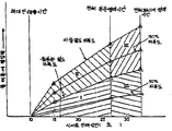
제1도는 인쇄 피복치와 여러 시이트 인쇄시간을 위해 잉크젯트로 인쇄되는 시이트기판을 지지하는 플래튼에 열입력을 표시하는 그래프.1 is a graph showing heat input to a platen supporting a sheet substrate printed with ink jet for printing coverage and various sheet printing times.
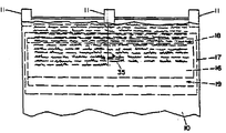
제2도는 본 발명에 따라 대표적인 온도제어의 플래튼 장치를 도시하는 개략 단면도.2 is a schematic cross-sectional view showing a representative temperature control platen device in accordance with the present invention.
제3도는 제2도의 선 Ⅲ-Ⅲ을 따라 취한 것으로 화살표의 방향에서 본 개략 단면도.3 is a schematic cross-sectional view taken along the line III-III of FIG. 2, seen in the direction of the arrow.
제4도는 종이와 플래튼 시스템으로 또 시스템으로부터의 에너지플럭스를 도시하는 것으로 본 발명의 다른 실시예를 도시한 개략 단면도.4 is a schematic cross-sectional view showing another embodiment of the present invention, showing the energy flux from and to the paper and platen system.
[발명의 상세한 설명]Detailed description of the invention
[기술분야][Technical Field]
본 발명은 잉크젯트시스템에 관한 것으로, 특히 고온용융잉크를 사용하기 위해 이런 잉크의 제어된 응고를 제공하는 새롭고 개량된 잉크젯트장치를 제공하는 것이다.The present invention relates to an ink jet system, and in particular to provide a new and improved ink jet apparatus for providing controlled solidification of such inks for use with hot melt inks.
[배경기술][Background]
물 또는 다른 기화성 용매를 포함한 잉크를 사용하는 잉크젯트시스템을 플랜튼으로 지지되는 종이와 같은 기판에 가해진 후 잉크의 건조(예를들면 용매의 기화)를 필요로 한다. 용매를 기초로 하는 잉크의 건조를 촉진하기 위해 가열된 플래튼이 잉크젯트장치에 미리 제공된다.Inkjet systems using ink containing water or other vaporizable solvents are applied to a substrate, such as paper supported by a platen, followed by drying of the ink (eg solvent vaporization). The heated platen is provided in advance in the inkjet apparatus to promote drying of the ink based on the solvent.
어떤 타입의 잉크젯트장치는 용매를 포함하지 않고 실온에서 옹고되는 "고온용융"잉크라 하는 잉크를 사용하며, 이 잉크는 기판에 젯트사용을 위한 가열에 의해 액화되고, 사용후 기판을 냉각시킴으로써 재응고된다.Some types of inkjet devices use an ink called a "hot melt" ink which contains no solvent and is admixed at room temperature, which is liquefied by heating the jet to the substrate and re-used by cooling the substrate after use. Solidifies.
더욱이 잉크젯트장치에 의해 기판에 고온용융잉크의 사용은 기판에 열을 전달한다. 게다가 고온 용융잉크의 응고는 기판과 지지플랜튼에 전달되는 열에너지를 방출하고, 이것은 용매를 기초로 하는 잉크의 사용에 일어나지 않는다. 고밀도의 피복으로 이것은 수용가능한 잉크침투에 대한 한계이상으로 종이와 플래튼의 온도를 상승시킨다.Moreover, the use of hot melt ink on a substrate by an ink jet apparatus transfers heat to the substrate. In addition, solidification of the hot melt ink releases thermal energy transferred to the substrate and support platen, which does not occur with the use of solvent-based inks. With a high density coating this raises the temperature of the paper and platen beyond the limits for acceptable ink penetration.
바람직한 정도로 종이와 같은 침투성 기판으로 고온용융잉크의 침투를 제어하기 위하여 고온용융잉크의 용융점에 가깝게 그러나 이하의 온도로 기판을 예열하는 것이 유리하다. 기판온도가 너무 냉각된다면 잉크는 짧은 거리의 침투후에 냉동된다. 이것은 돋을 새김특성으로 상승된 작은 방울과 영상으로 되게 한다. 더욱이 이런 잉크 방울 또는 영상은 조악한 부착을 갖게 될 수 있고 또는 접힘이나 주름의 작용으로 쉽게 긁히거나 벗겨지며 또는 다른 시이트에 갈라지거나 얼룩이 생기게 한다. 종이 온도가 너무 높다면 가령 잉크의 용융점 보다 더 높다면 잉크는 종이를 통하여 완전히 침투되기전에는 응고되지 않고 이에따라 "관통인쇄"라 하는 결점상태로 된다. 더욱이 고온용융잉크의 용융점 정도의 온도에 있는 기판에 인쇄된 영상은 저온기판 온도에서 인쇄된 영상보다 주목할만하게 다르게 나타난다. 이런 영상은 정상보다 큰 반점크기, 희미한 모서리, 가는 선의 퍼짐등의 성질을 나타낸다. 더욱이 잉크젯트장치에서 용매를 기초로 한 잉크의 사용을 위해 필요한 상태와는 대조적으로 잉크가 부착된 후 기판의 가열은 방울의 퍼짐을 제어하는 것에 비효율적이고 고온용융잉크를 사용할때 일어날 수 있는 상기 언급된 결점을 방지하는 것에도 비효율적이다. 그러므로 가열되지 않거나 단지 균등히 가열된 플래튼을 사용하는 현재의 공지된 잉크 젯트장치는 일정한 고품질의 영상을 만들기 위해 기판에 고온용융잉크의 효과적인 사용에 필요한 상태를 유지할 수 없다.It is advantageous to preheat the substrate close to the melting point of the hot melt ink but to a temperature below to control the penetration of the hot melt ink into a permeable substrate, such as paper, to the desired extent. If the substrate temperature is too cold, the ink is frozen after a short distance of penetration. This results in small droplets and images that are elevated with embossing characteristics. Moreover, such ink droplets or images may have coarse adherence or may be easily scratched or peeled off due to the action of folding or wrinkling or cracking or staining of other sheets. If the paper temperature is too high, for example, higher than the melting point of the ink, the ink will not solidify until it has fully penetrated through the paper, thus resulting in a defect called "penetration printing". Moreover, the image printed on the substrate at the temperature of the melting point of the hot melt ink appears remarkably different than the image printed at the low substrate temperature. These images show larger spot sizes than normal, faint edges, and the spread of fine lines. Furthermore, in contrast to the conditions necessary for the use of solvent-based ink in inkjet devices, the heating of the substrate after the ink has been deposited is inefficient in controlling the spread of droplets and may occur when using hot melt ink. It is also inefficient in preventing defects. Therefore, the current known ink jet apparatus using a platen that is not heated or only evenly heated cannot maintain the state necessary for the effective use of hot melt ink on a substrate to produce a constant high quality image.
[발명의 상세][Details of the Invention]
따라서 본 발명의 목적은 종래 기술의 상기 언급된 단점을 효과적으로 극복할 수 있는 새롭고 개량된 잉크젯트 장치를 제공하는 것이다.It is therefore an object of the present invention to provide a new and improved inkjet device which can effectively overcome the above mentioned disadvantages of the prior art.
본 발명의 다른 목적은 특히 고온용융잉크를 사용할 수 있도록 된 잉크젯트장치를 제공하는 것이다.Another object of the present invention is to provide an inkjet device, in particular, which makes it possible to use a hot melt ink.
본 발명의여러 목적 및 장점은 기판을 지지하고 열전도성을 갖는 플래튼과 히터를 구비하는 잉크젯트장치와, 제어된 방식으로 플래튼으로부터 열을 추출하기 위해 열펌프를 포함하고 플래튼과 열적으로 연통하여 배치된 열전기의 냉각설비를 제공함으로써 달성된다. 바람직하게 또한 장치는 바람직한 온도를 유지할 필요가 있을때 플래튼에 열을 공급하기 위해 온도제어 시스템에 응하는 열전기히터와, 열펌프를 제어하기 위한 온도 제어시스템을 포함한다. 더욱이 플래튼은 작동중에 플래튼에 열전달관계로 기판을 유지하기 위한 진공시스템을 바람직하게 포함한다.Various objects and advantages of the present invention include an inkjet device comprising a platen and a heater supporting a substrate and having a thermal conductivity, and a heat pump for extracting heat from the platen in a controlled manner and thermally with the platen. It is achieved by providing a cooling arrangement of thermoelectrics arranged in communication. Preferably the apparatus also includes a thermoelectric heater corresponding to the temperature control system for supplying heat to the platen when it is necessary to maintain the desired temperature and a temperature control system for controlling the heat pump. Moreover, the platen preferably comprises a vacuum system for holding the substrate in heat transfer relation to the platen during operation.
본 발명의 그 외의 목적 및 장점은 첨부 도면을 참고하여 다음이 설명으로 더 명백하게 될 것이다.Other objects and advantages of the present invention will become more apparent from the following description with reference to the accompanying drawings.
[발명을 실시하기 위한 최적모드][Optimal Mode for Carrying Out the Invention]
잉크젯트인쇄에서 종이상의 반점크기는 초기 방울의 양과 이 방울이 기판과 상호 작용하는 정도에 좌우되고, 이 상호작용은 퍼짐의 정도에 악영향을 미친다. 물을 기초로 하는 잉크젯트시스템에서 잉크는 섬유를 적제 하고, 방울은 섬유에 완전히 흡수될 때까지 퍼지는 경향이 있다.In inkjet printing, the spot size on paper depends on the amount of initial droplets and the extent to which the droplets interact with the substrate, and this interaction adversely affects the degree of spread. In water-based inkjet systems, the ink is loaded with fibers and the droplets tend to spread until they are fully absorbed by the fibers.
보통용지범위의 흡수특성이 다른 종이의 폭넓게 다른 인쇄특성을 만들 수 있을 정도로 크기 때문에 이것은 일반적으로 결점으로 간주된다. 고온용융잉크인쇄 시스템에서 잉크는 또한 종이 섬유를 젖게 하고, 그러나 방울의 퍼짐은 잉크의 냉각으로 한정되며, 이것은 잉크가 냉동될 때까지 또는 잉크의 점성이 퍼짐이동을 한정할 수 있을 정도로 크게 될 때까지 종이섬유와 열에너지를 공유한다. 다행스럽게 대부분의 종이는 적당히 유사한 비열을 가져서 방울의 퍼짐이 잉크의 응고온도에 비하여 잉크방울과 종이기판의 초기온도에 의해 주로 결정된다. 종이의 열특성의 유사성의 결과로써 기판온도가 적절히 제어된다면 유사한 영상은 다른 종이들상에 얻어질 수 있다.This is generally regarded as a defect because the absorption characteristics of plain paper ranges are large enough to produce a wide variety of different printing characteristics of different papers. In hot melt ink printing systems, the ink also wets the paper fibers, but the spreading of the droplets is limited to the cooling of the ink, which is until the ink is frozen or when the ink's viscosity becomes large enough to limit the spreading movement. Until they share the thermal energy with paper fibers. Fortunately, most papers have a moderately similar specific heat so that the spread of droplets is largely determined by the initial temperature of the ink droplets and the paper substrate relative to the solidification temperature of the ink. Similar images can be obtained on other papers if the substrate temperature is properly controlled as a result of the similarity of the thermal properties of the paper.
고온용융잉크젯트 프린터에서 종이와 같이 기판의 단위영역에 가해진 열에너지는 기판에 도달시 고온용융잉크의 온도와, 인쇄중 잉크로 기판의 피복과 고온용융잉크의 응고에너지에 좌우된다. 인쇄직후에 기판의 온도는 인쇄중에 가해진 열에너지와, 기판의 초기온도와, 기판의 열전달관계에 있는 플래튼과 같은 열전도성 요소의 온도에 좌우된다.The thermal energy applied to the unit area of the substrate, such as paper, in the hot melt inkjet printer depends on the temperature of the hot melt ink upon reaching the substrate, the coating of the substrate with the ink during printing, and the solidification energy of the hot melt ink. Immediately after printing, the temperature of the substrate depends on the thermal energy applied during printing, the initial temperature of the substrate, and the temperature of the thermally conductive element such as the platen in the heat transfer relationship of the substrate.
따라서 기판에 가해지는 온도이하의 선택된 온도에서 응고되는 고온 용융잉크는 기판과 이 기판의 지지플래튼이 사실상 선택된 온도이하의 낮은 온도에 있다면 거의 즉시 응고될 수 있고, 이것은 시스템의 시동중에 일어날 수 있다. 이런 즉시의 응고는 잉크의 응고전에 기판으로 고온용융잉크의 침투를 충분히 방지한다. 한편 기판과 이 기판을 지지하는 플래튼이 고온용융잉크의 응고온도에 근사하거나 이상의 온도에 있다면 예를들면 수초정도의 비교적 긴 시간이 응고에 필요하게 되고 이에 의해서 인쇄된 영상의 관통인쇄 또는 제어되지 않은 방울의 퍼짐을 허용하게 된다. 예를들면 0.023㎜의 전체 잉크두께를 제공하면서 1㎜에 11.8점의 선형밀도로 젯트에 초당 12,000방울의 비율로 기판에 130℃의 온도에서 다른 색깔의 잉크방울의 두 층을 가하는 96-젯트 헤드의 최근 고속 고온용융프린터는 인쇄작동중에 0.1㎜ 종이기판의 포용온도를 약 21℃ 정도로 상승시킨다. 이런 방식으로 고정된 플래튼위로 이동하는 기판의 연속된 인쇄로 플래튼 온도는 고온용융잉크의 응고점 이상이나 또는 응고점에 접근하는 레벨에 곧 도달한다.Thus, the hot melt ink that solidifies at a selected temperature below the temperature applied to the substrate can solidify almost immediately if the substrate and its support platen are at a temperature substantially below the selected temperature, which can occur during startup of the system. . This instant solidification sufficiently prevents penetration of the hot melt ink into the substrate prior to solidification of the ink. On the other hand, if the substrate and the platen supporting the substrate are close to or above the solidification temperature of the hot melt ink, for example, a relatively long time, for example, several seconds, is required for solidification so that the printed images cannot be penetrated or controlled. Allowing the spread of undropped drops. For example, a 96-jet head applying two layers of different colored ink droplets to a substrate at a temperature of 130 ° C at a rate of 12,000 drops per second to the jet at a linear density of 11.8 points per millimeter while providing a total ink thickness of 0.023 mm 'S recent high-temperature hot melt printers raise the inclusion temperature of 0.1 mm paper substrates to about 21 ° C during printing operations. With the continuous printing of the substrate moving over the fixed platen in this manner, the platen temperature will soon reach or exceed the freezing point of the hot melt ink.
동봉하는 도면의 제1도는 플래튼을 가로질러 이동하는 21.6㎝×27.9㎝의 종이시이트가 고온용융잉크로 인쇄될때 지지플래튼에 가해지는 열에너지를 그래프 형태로 대략 도시한다.FIG. 1 of the enclosed drawings shows, in graphical form, the thermal energy applied to the support platen when a 21.6 cm × 27.9 cm paper sheet moving across the platen is printed with hot melt ink.
제4도를 참고하여 이하에서 설명되는 바와같이 온도가 상승하는 경향이 있는 것으로 종이/플래튼 시스템에 정미열입력이 있는가 아니면 인쇄구역에서 온도가 감소하는 것으로 종이/플래튼 시스템으로부터 정미열유출이 있는가를 결정하는 다수의 에너지 플럭스가 있다. 열에너지는 잉크방울에 있는 엔탈피에 의해, 히터 제어기로 선택적으로 제공되는 임의의 전력에 의해, 또, 시스템으로 들어오는 종이의 열함유량에 의해 전도, 대류 및 복사를 경유하여 공기갭을 가로질러 가열된 인자판으로부터 열전달로 시스템에 입력된다. 시스템으로부터 에너지유출은 종이와 잉크에 있는 열에너지(종이의 입력온도보다 더 높은 온도에서 존재함)와, 대류를 통하여 주위 공기로 인자판에 의해 덮히지 않는 종이로부터의 또 플래튼으로부터의 열전달과, 판대를 통하여 전도를 경유하여 및/또는 선택적으로 열전기냉각기의 열펌프 작용을 경유하여 플래튼으로부터 주위의 구조물로 전달되는 열을 포함한다.Determining whether there is a net heat input in the paper / platen system as the temperature tends to rise as described below with reference to FIG. 4, or whether there is a net heat leakage from the paper / platen system by decreasing the temperature in the printing zone. There are a number of energy fluxes. Thermal energy is a factor that is heated across the air gap via conduction, convection and radiation by the enthalpy in the ink droplets, by any power selectively provided to the heater controller, and by the heat content of the paper entering the system. Heat is input into the system from the plate. The energy release from the system is the heat energy in the paper and ink (which is present at a higher temperature than the input temperature of the paper), the heat transfer from the platen and the platen, which is not covered by the platen with ambient air through convection, And heat transferred from the platen to the surrounding structure via conduction through the plate and / or optionally via the heat pump action of the thermoelectric cooler.
제1도에 도시된 바와같이 그래프에서 세로좌표로 표시되는 열입력은 시이트인쇄시간의 증가로 또 기판의 피복율의 증가로 증가된다. 여기서 최소로 약 10초에서부터 최대로 약 33초의 전형적인 시이트 인쇄시간 도시되고, 그래프에 도시된 바와같이 최고 정미열입력은 천천히 이동하는 시이트가 인자판에서 종이/플래튼 시스템으로의 열전달에 의해 또 고온잉크방울에 있는 엔탈피에 의해 송달받은 것보다 종이/플래튼 시스템으로부터의 적은 열에너지를 이동시키기 때문에 가장 느린 시이트 인쇄 시간에서 일어난다.As shown in FIG. 1, the heat input indicated by the ordinate in the graph increases with an increase in sheet printing time and an increase in the coverage of the substrate. A typical sheet print time is shown here, from a minimum of about 10 seconds to a maximum of about 33 seconds, and the highest net heat input, as shown in the graph, is indicated by the slow transfer of the sheet by the heat transfer from the platen to the paper / platen system and the high temperature ink. It occurs at the slowest sheet print time because it transfers less heat energy from the paper / platen system than was delivered by the enthalpy in the droplets.
유사하게 임의의 시이트 인쇄시간에서 플래튼으로의 열입력은 잉크로 피복된 시이트영역의 비율인 인쇄피복도의 증가로 증가된다. 두색 이상의 다른 색잉크가 사용되는 색잉크는 보통 적어도 어느 정도로 서로 중첩한다. 따라서 제1도에 있는 그래프는 50%와 100%의 시이트피복도에 대해서 뿐만 아니라 100%를 초과하여 150%와 200%의 시이트 피복도에 대해서 플래튼에 열입력을 도시하고, 이것은 두층의 잉크에 의해 전체 시이트의 피복도에 대응한다. 일반적으로 낮은 피복도의 시이트는 적은 인쇄시간을 필요로 한다.Similarly, the heat input to the platen at any sheet print time is increased with an increase in print coating, which is the proportion of sheet area covered with ink. Color inks in which two or more different color inks are used usually overlap one another at least to some extent. The graph in FIG. 1 thus shows the heat input to the platen for sheet coverage of 50% and 100% as well as for sheet coverage of 150% and 200% above 100%, which is caused by two layers of ink. Corresponds to the covering degree of the entire sheet. In general, low coverage sheets require less printing time.
제1도는 네섹션으로 분류된 Ⅰ, Ⅱ, Ⅲ과 Ⅳ에 있는 여러 인쇄상태하에서 플래튼에 열입력을 도시한다. 섹션 Ⅰ은 고온용융잉크의 단일층으로 충분한 밀도까지 21.6㎝×27.9㎝의 시이트중 보통의 전문 영역인 17.8㎝×22.9㎝를 인쇄할 때 플래튼에 열입력을 표시한다. 고온용융잉크의 충분한 두층까지 색인쇄중 시이트에 중첩관계로 사용될 때 플래튼에 전달된 열에너지는 Ⅱ로 지정된 섹션에 도시된다. 이 경우에 제1도에 도시된 바와같이 열에너지의 두배까지 플래튼에 전달된다.Figure 1 shows the heat input to the platen under various printing conditions in I, II, III and IV classified into four sections. Section I displays the heat input on the platen when printing a 17.8 cm × 22.9 cm, which is the normal specialty area of a 21.6 cm × 27.9 cm sheet to a sufficient density in a single layer of hot melt ink. The heat energy transferred to the platen when shown in the superimposed sheet on the sheet during indexing up to two sufficient layers of hot melt ink is shown in the section designated II. In this case up to twice the thermal energy is transferred to the platen as shown in FIG.
제1도에서 Ⅲ으로 지정된 섹션은 21.6㎝×27.9㎝의 "전체 페이지"영역에 즉 시이트의 우측모서리의 0.25㎝이내와 상부, 좌측 및 하단 모서리의 0.965㎝이내로 충분한 밀도까지 단일층의 잉크를 인쇄할 때 플래튼에 열입력을 표시하고, Ⅳ로 지정된 섹션은 고온용융잉크의 이중층까지 인쇄하는 전체페이지 영역에 대한 열입력을 표시한다. 원그림표와 같이 충실한 영역패턴의 색 인쇄로 조작은 플래튼에 매우 큰 열에너지 입력을 제공하면서 Ⅲ과 Ⅳ로 지정된 영역에 자주 있다.The section designated III in Fig. 1 prints a single layer of ink to a sufficient density within a " whole page " area of 21.6 cm by 27.9 cm, i.e. within 0.25 cm of the right edge of the sheet and within 0.965 cm of the top, left and bottom edges. Heat input on the platen, and the section designated IV indicates heat input for the entire page area printing up to the double layer of hot melt ink. Manipulation with color printing of faithful area patterns, as shown in the diagram, is often in areas designated III and IV, providing very high heat energy input to the platen.
플래튼 온도는 열입력의 비율뿐만 아니라 플래튼으로부터 열에너지의 제거비율에 좌우된다. 고온용융잉크 젯트장치의 적절한 조작을 확실하게 하는 선택된 플래튼 온도를 유지하기 위해 특히 섹션 Ⅲ과 Ⅳ에 도시된 바와같은 상태하에서 열에너지는 플래튼으로부터 빠르게 또 유효하게 제거되어야 한다. 플래튼으로부터 전도 또는 대류에 의하여 이동하는 공기흐름으로 열에너지의 제거는 부적절하고 특히 국부적인 순환공기온도가 조작설정점의 5℃ 또는 10℃내로 상승할때 부적절하다. 몇몇시기에 시스템은 최적작동을 위한 바람직한 한계내에 플래튼 온도를 유지하기 위해 충분히 정밀한 제어를 할 수 없다.The platen temperature depends not only on the rate of heat input but also on the rate of removal of thermal energy from the platen. In order to maintain the selected platen temperature to ensure proper operation of the hot melt ink jet apparatus, thermal energy must be quickly and effectively removed from the platen, especially under conditions as shown in sections III and IV. The removal of thermal energy by airflow moving by conduction or convection from the platen is inadequate, especially when the local circulation air temperature rises within 5 ° C or 10 ° C of the operating set point. At some time, the system may not have enough precise control to maintain the platen temperature within the desired limits for optimal operation.
예를들면 초기시동에서 전도 또는 대류적으로 냉각된 플래튼은 실온(예를들면 21℃)에 있게 되는 반면에 응고전에 종이와 같은 섬유기판으로 고온용융잉크의 충분한 침투를 허용하기 위하여 기판을 약 40℃에서 유지하는 것이 바람직하다. 시동시에 플래튼으로 열의 부가를 필요로 한다. 한편 상기 언급된 타입의 연속인쇄가 예를들면 130℃에서 고온용융잉크를 사용하게 될 때 플래튼 온도는 재빨리 40℃에 도달하여 초과하고, 고온용융잉크의 응고온도에 접근하며, 이에 의해 플래튼으로부터 열의 제거를 필요로 한다. 더욱이 단일색 본문으로 간헐적으로 원그림표와 같이 치밀한 색으로 된 도해의 재생에서의 발생과 같이 인쇄비율에서 자주 있으며 극심한 변화는 인쇄될 기판과 플래튼의 온도에서 대응하는 극심한 변동을 야기할 것이고, 기판으로 불충분한 잉크침투와 관통인쇄의 교호상태를 만들게 된다.For example, at initial startup, the platen, which is either conductively or convectively cooled, is at room temperature (eg 21 ° C.), while the substrate is weakened to allow sufficient penetration of the hot melt ink into a fibrous substrate such as paper prior to solidification. It is preferable to maintain at 40 degreeC. It requires the addition of heat to the platen at start up. On the other hand, when the continuous printing of the above-mentioned type uses hot melt ink at 130 ° C., for example, the platen temperature quickly reaches and exceeds 40 ° C., thereby approaching the solidification temperature of the hot melt ink, whereby the platen Requires removal of heat from Moreover, in the monochromatic text, there are frequent changes in the printing ratio, such as the occurrence of intermittent reproductions of dense color schemes such as circle diagrams, and extreme changes will cause corresponding extreme fluctuations in the temperature of the substrate and platen to be printed. Inadequate ink penetration and through-printing result in alternating states.
제2도 및 제3도에 도시된 본 발명의 대표적인 실시예에서 고온용융잉크 젯트장치의 플래튼 온도는 연속적인 최적 인쇄상태를 제공하도록 바람직한 레벨에서 유지된다. 제2도에 도시된 바와같이 종이와 같은 기판재료의 시이트 또는 웨브(10)는 잉크젯트헤드(13)와 플래튼 조립체(14)사이에 있는 갭을 통하여 기판재료를 이동시키기 위해 화살표로 표시된 방향으로 회전하는 한 셋트의 구동로율(11), (12)을 포함하는 구동시스템으로 구동된다. 잉크젯트헤드는 종래의 방식으로 웨브(10)의 이동방향에 가로질러 연장하는 연속하는 통로에 있는 기판의 표면에 잉크젯트방울(15)의 배열을 사출하기 위하여 제2도에 평면에 수직으로 왕복운동한다. 플래튼조립체(14)는 진공펌프(21) 또는 송풍기로 이끄는 하우징의 후방에 있는 배기구(20)와 플래튼(16)의 상부 및 하부 모서리에 있는 슬릿개구(18), (19)를 구비하는 하우징(17)에 장착될 플래튼(16)을 포함한다.In the exemplary embodiment of the present invention shown in FIGS. 2 and 3, the platen temperature of the hot melt ink jet apparatus is maintained at a desired level to provide a continuous optimum printing state. As shown in FIG. 2, the sheet or
하우징(17)은 사실상 기밀로 될 수 있고 또는 대기증으로 사실상 연속적인 열제거를 위하여 종이가 면개구를 덮을 때에도 부가적인 공기구가 제공될 수 있다. 제3도에 자세히 도시된 바와같이 플래튼(16)과 인접한 진공 슬릿(18), (19)은 기판재료의 웨브(10)의 폭을 가로질러 사실상 연장되고, 웨브(10)는 인접한 핀치로울(12)과 함께 대응하는 닙을 형성하는 세개의 구동로울(11)로 구동되며, 그 중 하나가 제2도에 도시된다.The
기판온도가 관통인쇄를 허용함이 없이 고온용융잉크방울(15)의 충분한 침투를 허용하도록 바람직한 레벨에서 유지되는 것을 확실하게 하기 위하여 온도 제어유닛(22)은 라인(23)을 통하여 플래튼(16)의 온도를 검출한다. 가령 장치의 시동시에 바람직한 플래튼온도를 유지하기 위해 플래튼을 가열할 필요가 있다면, 또는 낮은 시이트 인쇄시간으로 또는 낮은 피복도에서 인쇄할 때 제어유닛(22)은 바람직한 작동온도에 도달할 때까지 플래튼을 가열하기 위해 종래의 저항형 히터나 더어미스터(25)로 라인(24)을 통하여 전력을 공급한다.In order to ensure that the substrate temperature is maintained at a desired level to allow sufficient penetration of the hot melt ink droplets 15 without allowing penetration printing, the
더욱이 전기열펌프(26)는 플래튼(16)과 열접촉하는 것으로 예를들면 멜커로부터 입수가능한 CP 1.0-63-06L으로 지정된 타입의 열전기냉각기(28)로 라인(27)에 의해 연결된다. 온도제어 유닛(22)이 예를들면 큰 시이트 인쇄시간으로 또는 큰 피복도에서 인쇄하게 되는 바람직한 레벨이상의 플래튼 온도를 검출할때 열싱크(30)로 열에너지를 차례로 전달하는 펌프로 라인(27)을 통하여 열전기 냉각기(28)로부터 열에너지를 전달하도록 라인(29)을 통하여 열펌프를 활동시킨다. 예를들면 전체 플래튼 조립체를 위한 구조적인 지지부재로될 수 있는 열싱크(30)는 복사 및 대류적인 열소산을 위한 핀(31)을 구비하고, 열펌프(26)가 바람직한 플래튼 온도를 유지하도록 충분히 큰 열제거율을 확실하게 하기 위하여 강제공기냉각장치(32)를 구비한다. 열에너지가 바람직한 온도를 유지하도록 열펌프(26)와 열전기 냉각기(28)의 용량을 초과하는 비율로 잉크젯트헤드(13)에 의하여 플래튼(16)과 웨브(10)에 공급되는 극심한 상태에 직면하면 제어유닛(22)은 열펌프(26)가 다시 일정한 플래튼 온도를 유지할 수 있을 때까지 잉크젯트헤드(13)에 의해 잉크방울이 웨브(10)에 작용하는 비율을 감소시키는 잉크젯트시스템 제어장치(34)로 라인(33)을 통하여 지령신호를 보낼 수 있다. 플래튼온도가 기판(10)으로 충분한 침투후에 배열(15)에 있는 잉크방울의 신속한 응고를 확실하게 하도록 제어된다고 할지라도 기판이 제3도에 도시된 중심구동로울(11)에 대향하는 핀치로울(12)로 잉크의 갈라짐을 방지하기 위해 구동로울(11)과 핀치로울(12)사이에 있는 닙에 도달할 때 응고된 잉크방울의 온도는 충분히 낮지 않을 수 있다. 이 가능성을 피하기 위해 작은 억누름 구역은 열펌프(26)에 라인(36)을 통하여 연결된 다른 열전기 냉각기(35)에 의해 제공되고, 열펌프는 그 구역에서 잉크의 완전한 응고를 확실하게 하기 위해 플래튼(16)의 온도보다 적어도 10℃ 낮은 온도를 그 구역에서 유지하도록 배열된다.Furthermore, the electric heat pump 26 is connected by
제3도에 도시된 바와같이 열전기 냉각기(35)는 구동로울(11)과 이에 관련된 핀치로울과 정렬되어서 이들 로울사이를 지나는 웨브(10)의 스트립이 요소(35)로 냉각된다. 한편 웨브(10)의 모서리에는 다른 구동로울(11)과 이에 관련된 핀치로울이 인쇄를 하지 않는 좁은 여백의 가장자리에 위치된다. 따라서 억누름은 이구역에서 불필요하다.As shown in FIG. 3, the
다른 플래튼 실시예에서 온도가 제어된 플래튼의 하류에 있는 억누름구역은 종이의 폭을 가로질러 완전히 제공될 수 있다. 예를들면 상기 억누름구역은 적절한 열싱크 능력을 플래튼지지부재의 일부로 될 수 있다.In other platen embodiments, the depression zone downstream of the temperature controlled platen may be provided completely across the width of the paper. For example, the depression zone may be part of the platen support member with adequate heat sink capability.
작동에 있어서 플래튼(16)은 히터(25)에 의해 40℃ 정도의 바람직한 온도로 상승될 필요가 있다면 가열된다. 진공펌프(21)는 웨브가 구동로울(11)과 이에 관련된 핀치로울(12)에 의해 나아감에 따라 웨브를 플래튼(16)과 열접촉 하면서 유지되도록 제2도에 화살표로 도시한 바와같이 개구(18), (19)를 통하여 공기를 흡수하고 하우징(17)으로부터 공기를 배기한다. 잉크젯트헤드(13)는 웨브(10)에 고온용융잉크(15)를 스프레이하고, 플래튼 온도의 증가는 제어유닛(22)으로 검출되며, 열펌프(20)가 열전기 냉각기(28)로부터 열싱크(30)와 핀(31)으로 열에너지를 전달하게 하고, 이 열에너지가 강제공기 냉각시스템(32)에 의해 이로부터 제거된다.In operation, the
종래의 고온용융잉크에 대해 잉크젯트헤드(13)는 예를들면 130℃의 젯팅온도에서 잉크를 유지하고, 그러나 잉크는 예를들면 60℃에서 응고되며, 관통인쇄가 일어나기 전에 또 바람직한 침투정도후 응고되도록 하기 위해 플래튼(16)은 예를들면 40℃의 선택된 낮은 온도의 약 3 내지 5℃내에서 유지되어야 한다. 그러나 잉크젯트장치의 정상작동중에 플래튼 조립체(14)와 이의 주변성분들의 주위온도는 40℃ 정도나 이상으로 될 것이다. 따라서 열펌프(26)는 시스템의 작동에서 무활동 주기중에도 열전기 냉각기(28), (32)에서 열싱크(30)로 열을 연속적으로 전달하도록 배치될 수 있다. 더욱이 잉크젯트작동중에 특히 제1도에 있는 영역 Ⅱ와 Ⅳ에서의 작동중에 사실상 더 많은 열이 플래튼으로부터 추출되어 열싱크(30)로 전달되어서 열싱크가 예를들어 60 내지 65℃의 비교적 높은 온도로 가열될 수 있고, 열에너지는 강제공기시스템(32)에 의해 열싱크(30)와 핀(31)으로부터 제거된다. 동시에 억누름구역에 있는 열전기 냉각기(32)는 핀치로울에 의한 결합전에 잉크의 완전응고를 확실하게 하면서 예를들면 30℃에서 플래튼의 나머지 보다 10℃ 더 낮은 상태로 유지된다.For conventional hot melt inks, the
인쇄된 영상의 크기와 성질이 폭넓게 변할 수 있기 때문에 한면에서 다른 면으로의 온도변화도를 극소화하기 위해 큰 측면 열전도율로 온도가 제어된 플래튼을 사용할 필요가 있다. 알루미늄과 구리는 적절한 플래튼 재료이지만 플래튼의 단면적은 알루미늄의 경우에 3.2㎠ 또는 이보다 더클 정도로 되어야 한다. 이런 플래튼은 큰 부피이고 큰 공간과 전력을 필요로 하거나 장시간동안 작동온도까지 가열될 수 있다. 이런 이유 때문에 에너지를 전달하기 위해 액체의 증발과 응축으로 열파이프의 특성을 구체화하는 구조가 채용될 수 있다.Because the size and nature of the printed image can vary widely, it is necessary to use temperature controlled platens with large lateral thermal conductivity to minimize temperature gradients from one side to the other. Aluminum and copper are suitable platen materials, but the platen should have a cross-sectional area of 3.2 cm2 or larger for aluminum. These platens are bulky and require large space and power or can be heated to operating temperatures for extended periods of time. For this reason, a structure may be employed to specify the characteristics of the heat pipe by evaporation and condensation of the liquid to transfer energy.
다른 문제점은 웨브가 인쇄구역에 있는 플래튼을 가로질러 이동함에 따라 웨브의 제어에서 일어날 수 있다. 한 문제점은 필름 매체(예를들면 마일러)의 차동 열팽창에 관한 것이고, 다른 것은 플래튼에 의해 가열되어 건조됨에 따라 종이의 차동수축에 관한 것이다. 이런 경우에 웨브는 뒤틀리거나 주름잡힐 수 있고 0.13㎜ 이상으로 플래튼 표면에서 떨어지며, 이것은 종이와 플래튼 사이에서 열적인 연결을 퇴화시키고 또한 특히 양방향의 인쇄의 경우에 젯트의 충격점을 변화시킴으로써 점배치의 정밀도를 퇴화시킨다.Another problem may arise in the control of the web as the web moves across the platen in the printing zone. One problem relates to differential thermal expansion of film media (eg mylar) and the other relates to differential shrinkage of paper as it is heated and dried by the platen. In this case the web can be warped or creased and fall off the platen surface by more than 0.13 mm, which degrades the thermal connection between the paper and the platen and also changes the point of impact of the jet, especially in the case of bidirectional printing. Deteriorate the precision of the placement.
이런 문제점을 피하기 위해 제4도에 도시된 플래튼 형상이 사용될 수 있다. 이 배열에서 잉크젯트헤드(41)는 종이(43)를 곡면형상으로 유지되게 하여 뒤틀림이나 주름짐에 대해 보강하는 곡면플래튼(44)에 의해 지지되는 종이(43)의 웨브를 향하여 잉크방울(42)을 사출한다. 적절한 곡면 플래튼(44)은 약 5 내지 10인치의 곡률반경을 가지고, 인쇄구역에 있는 제2도를 참고하여 설명된 타입의 온도가 제어된 부분(45)과 곡면 입구부(46) 그리고 곡면출구부(47)를 구비한다. 입구 및 출구부(46), (47)는 온도가 제어된 부분(45)의 다음에 10°와 적어도 10°를 능가하여 연장된다.To avoid this problem, the platen shape shown in FIG. 4 can be used. In this arrangement, the
따라서 온도제어부는 곡면의 종이 통로의 전체길이에 대해 연장될 필요는 없으나 종이 길이의 약 1.27㎜만을 점유할 수 있고, 곡면 종이통로의 입구부(46)와 출구부(47)는 제2도에 도시된 타입의 종이공급로울로 지나기 전에 종이 처리나 억누름에 더 적절한 온도에 있다. 하우징(48)은 플래튼(45)을 위한 온도제어구역을 에워싸며, 제2도를 참고하여 설명된 타입의 열전기냉각기를 포함할 수 있는 온도제어성분(49)은 온도제어구역에 있는 플래튼(45)과 접촉하여 장착된다. 동력라인(50)은 플래튼에 열을 부가할 필요가 있을때 플래튼(45)에 있는 히터에 에너지를 가한다.Therefore, the temperature control portion need not extend over the entire length of the curved paper passage, but can occupy only about 1.27 mm of the paper length, and the
제4도에 도시된 배열에서 종이/플래튼 시스템으로부터와 시스템에 에너지플럭스는 다음과 같이 표현된다.In the arrangement shown in FIG. 4 the energy flux from and to the paper / platen system is expressed as follows.
[종이/플래튼 시스템에 에너지 플럭스][Energy Flux on Paper / Platen Systems]
q1=잉크젯트헤드(41)로부터 복사열전달q1 = radiant heat transfer from the
q2=공기를 통한 전도q2 = conduction through air
q3=잉크젯트헤드(41)로부터 플래튼에 대류q3 = convection from the
E=잉크방울에 있는 엔탈피E = Enthalpy in Ink Drops
q4=온도 Tin에서 도입종이에 있는 열에너지q4 = thermal energy in the introduced paper at temperature T in
P=히터에 의해 플래튼으로 전달된 열P = heat transferred to the platen by the heater
[종이/플래튼 시스템으로부터 에너지 플럭스][Energy Flux from Paper / Platen System]
q5=온도 Tout에서 종이와 잉크에 배출하는 열에너지q5 = thermal energy released to paper and ink at temperature T out
q6=대류열전달에 의해 플래튼으로부터 공기로 이동된 열에너지q6 = thermal energy transferred from platen to air by convective heat transfer
q7=대지를 통하는 전도에 의해 및/또는 열펌프 작용에 의해 플래튼으로부터 제거되는 열q7 = heat removed from the platen by conduction through the ground and / or by heat pump action
본 발명이 특정 실시예를 참고하여 설명하였지만 많은 변형과 변화는 본 기술분야에 숙련된 사람들에게 쉽게 될 수 있다. 따라서 이런 모든 변형과 변화는 다음 청구범위로 한정되는 바와같이 본 발명의 범위내에 포함된다.Although the present invention has been described with reference to specific embodiments, many variations and modifications can be readily made by those skilled in the art. Accordingly, all such modifications and variations are intended to be included within the scope of this invention as defined by the following claims.
Claims (19)
Applications Claiming Priority (3)
| Application Number | Priority Date | Filing Date | Title |
|---|---|---|---|
| US07/094,664 US4751528A (en) | 1987-09-09 | 1987-09-09 | Platen arrangement for hot melt ink jet apparatus |
| US94664 | 1987-09-09 | ||
| PCT/US1988/003074 WO1989002576A1 (en) | 1987-09-09 | 1988-09-01 | Platen arrangement for hot melt ink jet apparatus |
Publications (2)
| Publication Number | Publication Date |
|---|---|
| KR890701998A KR890701998A (en) | 1989-12-22 |
| KR920006962B1 true KR920006962B1 (en) | 1992-08-22 |
Family
ID=22246443
Family Applications (1)
| Application Number | Title | Priority Date | Filing Date |
|---|---|---|---|
| KR1019890700815A KR920006962B1 (en) | 1987-09-09 | 1988-09-01 | Platen arrangement for hot melt ink jet apparatus |
Country Status (8)
| Country | Link |
|---|---|
| US (2) | US4751528A (en) |
| EP (1) | EP0333819B1 (en) |
| JP (1) | JPH0825274B2 (en) |
| KR (1) | KR920006962B1 (en) |
| BR (1) | BR8807197A (en) |
| CA (1) | CA1318547C (en) |
| DE (1) | DE3883371T2 (en) |
| WO (1) | WO1989002576A1 (en) |
Families Citing this family (146)
| Publication number | Priority date | Publication date | Assignee | Title |
|---|---|---|---|---|
| US4751528A (en) * | 1987-09-09 | 1988-06-14 | Spectra, Inc. | Platen arrangement for hot melt ink jet apparatus |
| US5023111A (en) * | 1988-08-10 | 1991-06-11 | Spectra, Inc. | Treatment of hot melt ink images |
| US4873134A (en) * | 1988-08-10 | 1989-10-10 | Spectra, Inc. | Hot melt ink projection transparency |
| US5500658A (en) * | 1987-09-11 | 1996-03-19 | Canon Kabushiki Kaisha | Ink jet recording apparatus having a heating member and means for reducing moisture near an ink discharge port of a recording head |
| GB2211471B (en) * | 1987-10-27 | 1991-10-02 | Brother Ind Ltd | Hot-melt type ink jet recording apparatus |
| US4971408A (en) * | 1988-11-15 | 1990-11-20 | Spectra, Inc. | Remelting of printed hot melt ink images |
| JP2891374B2 (en) * | 1988-06-03 | 1999-05-17 | スペクトラ インコーポレーテッド | Control of ink droplet diffusion in hot-melt ink jet printing |
| US5105204A (en) * | 1988-06-03 | 1992-04-14 | Spectra, Inc. | Subtractive color hot melt ink reflection images on opaque substrates |
| US5114747A (en) * | 1988-08-10 | 1992-05-19 | Spectra, Inc. | Treatment of hot melt ink images |
| US4889761A (en) * | 1988-08-25 | 1989-12-26 | Tektronix, Inc. | Substrates having a light-transmissive phase change ink printed thereon and methods for producing same |
| JPH0262275A (en) * | 1988-08-30 | 1990-03-02 | Brother Ind Ltd | Recording apparatus |
| US5151120A (en) * | 1989-03-31 | 1992-09-29 | Hewlett-Packard Company | Solid ink compositions for thermal ink-jet printing having improved printing characteristics |
| US5182571A (en) * | 1990-02-26 | 1993-01-26 | Spectra, Inc. | Hot melt ink jet transparency |
| US5411825A (en) * | 1990-10-16 | 1995-05-02 | Xerox Corporation | Heat development process of migration imaging members |
| CA2049571C (en) * | 1990-10-19 | 2004-01-13 | Kent D. Vincent | High definition thermal ink-jet printer |
| US5099256A (en) * | 1990-11-23 | 1992-03-24 | Xerox Corporation | Ink jet printer with intermediate drum |
| US5196241A (en) * | 1991-04-08 | 1993-03-23 | Tektronix, Inc. | Method for processing substrates printed with phase-change inks |
| JPH0569541A (en) * | 1991-09-17 | 1993-03-23 | Brother Ind Ltd | Ink discharge device of ink-jet printer |
| US5392065A (en) * | 1991-10-15 | 1995-02-21 | Brother Kogyo Kabushiki Kaisha | Ink jet printer using hot melt ink |
| JPH05104819A (en) * | 1991-10-18 | 1993-04-27 | Brother Ind Ltd | Printer |
| DE69316432T2 (en) * | 1992-04-28 | 1998-05-07 | Hewlett Packard Co | Optimizing print quality and reliability in a CYMK printing system |
| US5406316A (en) * | 1992-05-01 | 1995-04-11 | Hewlett-Packard Company | Airflow system for ink-jet printer |
| US5723202A (en) * | 1992-05-01 | 1998-03-03 | Hewlett-Packard Co. | Transparent printer media with reflective strips for media sensing |
| US5287123A (en) * | 1992-05-01 | 1994-02-15 | Hewlett-Packard Company | Preheat roller for thermal ink-jet printer |
| US5456543A (en) * | 1992-05-01 | 1995-10-10 | Hewlett-Packard Company | Printer motor drive with backlash control system |
| DE69304774T2 (en) * | 1992-05-01 | 1997-02-20 | Hewlett Packard Co | Heater blower assembly in a color jet printer |
| DE69310994T2 (en) * | 1992-05-01 | 1997-10-02 | Hewlett Packard Co | Thermal inkjet printer with a heating element, which is supplied with variable thermal energy for different printing media |
| US5329295A (en) * | 1992-05-01 | 1994-07-12 | Hewlett-Packard Company | Print zone heater screen for thermal ink-jet printer |
| US5296873A (en) * | 1992-05-01 | 1994-03-22 | Hewlett-Packard Company | Airflow system for thermal ink-jet printer |
| US5399039A (en) * | 1992-05-01 | 1995-03-21 | Hewlett-Packard Company | Ink-jet printer with precise print zone media control |
| US5479199A (en) * | 1992-05-01 | 1995-12-26 | Hewlett-Packard Company | Print area radiant heater for ink-jet printer |
| US5581289A (en) * | 1993-04-30 | 1996-12-03 | Hewlett-Packard Company | Multi-purpose paper path component for ink-jet printer |
| US5406321A (en) * | 1993-04-30 | 1995-04-11 | Hewlett-Packard Company | Paper preconditioning heater for ink-jet printer |
| US5461408A (en) * | 1993-04-30 | 1995-10-24 | Hewlett-Packard Company | Dual feed paper path for ink-jet printer |
| US5622897A (en) * | 1993-05-20 | 1997-04-22 | Compaq Computer Corporation | Process of manufacturing a drop-on-demand ink jet printhead having thermoelectric temperature control means |
| US5506609A (en) * | 1993-06-30 | 1996-04-09 | Apple Computer, Inc. | Minimizing color bleed while maximizing throughput for color printing |
| US5532720A (en) * | 1993-09-15 | 1996-07-02 | Quad/Tech, Inc. | Solvent recovery system for ink jet printer |
| US5539437A (en) * | 1994-01-10 | 1996-07-23 | Xerox Corporation | Hybrid thermal/hot melt ink jet print head |
| US5751303A (en) * | 1994-11-10 | 1998-05-12 | Lasermaster Corporation | Printing medium management apparatus |
| US6233398B1 (en) | 1994-12-29 | 2001-05-15 | Watlow Polymer Technologies | Heating element suitable for preconditioning print media |
| US5835679A (en) | 1994-12-29 | 1998-11-10 | Energy Converters, Inc. | Polymeric immersion heating element with skeletal support and optional heat transfer fins |
| US7237872B1 (en) * | 1995-05-02 | 2007-07-03 | Fujifilm Dimatrix, Inc. | High resolution multicolor ink jet printer |
| US5797329A (en) * | 1995-05-16 | 1998-08-25 | Dataproducts Corporation | Hot melt ink printer and method printing |
| US6133355A (en) * | 1995-09-27 | 2000-10-17 | 3D Systems, Inc. | Selective deposition modeling materials and method |
| US6305769B1 (en) | 1995-09-27 | 2001-10-23 | 3D Systems, Inc. | Selective deposition modeling system and method |
| US5774141A (en) * | 1995-10-26 | 1998-06-30 | Hewlett-Packard Company | Carriage-mounted inkjet aerosol reduction system |
| US5793398A (en) * | 1995-11-29 | 1998-08-11 | Levi Strauss & Co. | Hot melt ink jet shademarking system for use with automatic fabric spreading apparatus |
| US5593486A (en) * | 1995-12-05 | 1997-01-14 | Xerox Corporation | Photochromic hot melt ink compositions |
| US5655201A (en) * | 1995-12-21 | 1997-08-05 | Xerox Corporation | Tapered rollers for migration imaging system |
| US5700316A (en) * | 1996-03-29 | 1997-12-23 | Xerox Corporation | Acoustic ink compositions |
| US5688312A (en) * | 1996-03-29 | 1997-11-18 | Xerox Corporation | Ink compositions |
| US5747554A (en) * | 1996-03-29 | 1998-05-05 | Xerox Corporation | Ink compositions |
| US5667568A (en) * | 1996-03-29 | 1997-09-16 | Xerox Corporation | Hot melt ink compositions |
| US5698017A (en) * | 1996-09-27 | 1997-12-16 | Xerox Corporation | Oxazoline hot melt ink compositions |
| US5693128A (en) * | 1997-01-21 | 1997-12-02 | Xerox Corporation | Phase change hot melt ink compositions |
| US5844020A (en) * | 1997-03-31 | 1998-12-01 | Xerox Corporation | Phase change ink compositions |
| US6193349B1 (en) | 1997-06-18 | 2001-02-27 | Lexmark International, Inc. | Ink jet print cartridge having active cooling cell |
| AUPP653998A0 (en) * | 1998-10-16 | 1998-11-05 | Silverbrook Research Pty Ltd | Micromechanical device and method (ij46B) |
| AUPP654598A0 (en) * | 1998-10-16 | 1998-11-05 | Silverbrook Research Pty Ltd | Micromechanical device and method (ij46h) |
| US5931995A (en) * | 1997-09-23 | 1999-08-03 | Xerox Corporation | Ink compositions |
| US5922117A (en) * | 1997-09-23 | 1999-07-13 | Xerox Corporation | Ink compositions containing alcohols |
| US5958119A (en) * | 1997-09-23 | 1999-09-28 | Xerox Corporation | Hot melt ink compositions |
| US5876492A (en) * | 1997-09-23 | 1999-03-02 | Xerox Corporation | Ink compositions containing esters |
| US5902390A (en) * | 1997-09-23 | 1999-05-11 | Xerox Corporation | Ink compositions containing ketones |
| JPH11139017A (en) * | 1997-11-14 | 1999-05-25 | Hitachi Koki Co Ltd | Solid ink printing original plate, and its manufacture |
| JPH11139016A (en) * | 1997-11-14 | 1999-05-25 | Hitachi Koki Co Ltd | Solid ink printing original plate, and its manufacture |
| US6293638B1 (en) | 1998-02-04 | 2001-09-25 | Spectra, Inc. | Bar code printing on cartons with hot melt ink |
| US5989325A (en) * | 1998-03-05 | 1999-11-23 | Xerox Corporation | Ink compositions |
| US6742873B1 (en) * | 2001-04-16 | 2004-06-01 | Silverbrook Research Pty Ltd | Inkjet printhead construction |
| US7677686B2 (en) * | 1998-10-16 | 2010-03-16 | Silverbrook Research Pty Ltd | High nozzle density printhead ejecting low drop volumes |
| US7182431B2 (en) * | 1999-10-19 | 2007-02-27 | Silverbrook Research Pty Ltd | Nozzle arrangement |
| JP2002527272A (en) * | 1998-10-16 | 2002-08-27 | シルバーブルック リサーチ プロプライエタリイ、リミテッド | Improvements on inkjet printers |
| US7419250B2 (en) * | 1999-10-15 | 2008-09-02 | Silverbrook Research Pty Ltd | Micro-electromechanical liquid ejection device |
| US7028474B2 (en) * | 1998-10-16 | 2006-04-18 | Silverbook Research Pty Ltd | Micro-electromechanical actuator with control logic circuitry |
| US7216956B2 (en) * | 1998-10-16 | 2007-05-15 | Silverbrook Research Pty Ltd | Printhead assembly with power and ground connections along single edge |
| US6059871A (en) * | 1998-11-30 | 2000-05-09 | Xerox Corporation | Ink compositions |
| US6045607A (en) * | 1999-03-30 | 2000-04-04 | Xerox Corporation | Ink compositions |
| US6319310B1 (en) | 1999-03-30 | 2001-11-20 | Xerox Corporation | Phase change ink compositions |
| US6132499A (en) * | 1999-07-29 | 2000-10-17 | Xerox Corporation | Inks |
| US6187082B1 (en) | 1999-03-30 | 2001-02-13 | Xerox Corporation | Ink compositions |
| US6071333A (en) * | 1999-04-27 | 2000-06-06 | Xerox Corporation | Ink compositions |
| US6096124A (en) * | 1999-04-27 | 2000-08-01 | Xerox Corporation | Ink compositions |
| US6106601A (en) * | 1999-04-27 | 2000-08-22 | Xerox Corporation | Ink compositions |
| US6110265A (en) | 1999-04-27 | 2000-08-29 | Xerox Corporation | Ink compositions |
| US6096125A (en) * | 1999-04-27 | 2000-08-01 | Xerox Corporation | Ink compositions |
| US6066200A (en) * | 1999-04-27 | 2000-05-23 | Xerox Corporation | Ink compositions |
| US6086661A (en) * | 1999-04-27 | 2000-07-11 | Xerox Corporation | Ink compositions |
| US6263158B1 (en) | 1999-05-11 | 2001-07-17 | Watlow Polymer Technologies | Fibrous supported polymer encapsulated electrical component |
| US6188051B1 (en) | 1999-06-01 | 2001-02-13 | Watlow Polymer Technologies | Method of manufacturing a sheathed electrical heater assembly |
| US6106599A (en) * | 1999-06-29 | 2000-08-22 | Xerox Corporation | Inks |
| US6392208B1 (en) | 1999-08-06 | 2002-05-21 | Watlow Polymer Technologies | Electrofusing of thermoplastic heating elements and elements made thereby |
| US6306203B1 (en) | 1999-09-23 | 2001-10-23 | Xerox Corporation | Phase change inks |
| US6336722B1 (en) | 1999-10-05 | 2002-01-08 | Hewlett-Packard Company | Conductive heating of print media |
| US6505927B2 (en) | 1999-12-15 | 2003-01-14 | Eastman Kodak Company | Apparatus and method for drying receiver media in an ink jet printer |
| US6328440B1 (en) * | 2000-01-07 | 2001-12-11 | Hewlett-Packard Company | Buckling control for a heated belt-type media support of a printer |
| US6322619B1 (en) | 2000-02-22 | 2001-11-27 | Xerox Corporation | Ink compositions |
| US6361162B1 (en) | 2000-03-01 | 2002-03-26 | Lexmark International, Inc. | Method and apparatus for fixing ink to a print receiving medium |
| US6392206B1 (en) | 2000-04-07 | 2002-05-21 | Waltow Polymer Technologies | Modular heat exchanger |
| US6433317B1 (en) | 2000-04-07 | 2002-08-13 | Watlow Polymer Technologies | Molded assembly with heating element captured therein |
| US6350795B1 (en) | 2000-06-07 | 2002-02-26 | Xerox Corporation | Ink compositions |
| US6287373B1 (en) | 2000-06-22 | 2001-09-11 | Xerox Corporation | Ink compositions |
| US6398857B1 (en) | 2000-08-03 | 2002-06-04 | Xerox Corporation | Phase change inks |
| US6372030B1 (en) | 2000-08-03 | 2002-04-16 | Xerox Corporation | Phase change inks |
| US6395077B1 (en) | 2000-08-03 | 2002-05-28 | Xerox Corporation | Phase change inks |
| US6336963B1 (en) | 2000-08-03 | 2002-01-08 | Xerox Corporation | Phase change inks |
| US6328793B1 (en) | 2000-08-03 | 2001-12-11 | Xerox Corporation | Phase change inks |
| US6519835B1 (en) | 2000-08-18 | 2003-02-18 | Watlow Polymer Technologies | Method of formable thermoplastic laminate heated element assembly |
| US6432184B1 (en) | 2000-08-24 | 2002-08-13 | Xerox Corporation | Ink compositions |
| US6461417B1 (en) | 2000-08-24 | 2002-10-08 | Xerox Corporation | Ink compositions |
| US6604803B1 (en) | 2000-09-12 | 2003-08-12 | Canon Kabushiki Kaisha | Printer which compensates for paper unevenness |
| US6557961B2 (en) | 2001-06-22 | 2003-05-06 | Canon Kabushiki Kaisha | Variable ink firing frequency to compensate for paper cockling |
| FR2816546B1 (en) * | 2000-11-10 | 2003-08-29 | Leroux Gilles Sa | METHOD OF RELIEF MARKING OF A SUPPORTED OBJECT IN PLASTIC MATERIAL AND DEVICE IMPLEMENTING THE METHOD |
| US6460990B2 (en) * | 2000-12-01 | 2002-10-08 | Hewlett-Packard Co. | Non-warping heated platen |
| US6406140B1 (en) | 2000-12-08 | 2002-06-18 | Hewlett-Packard Company | Anisotropic thermal conductivity on a heated platen |
| US6539171B2 (en) | 2001-01-08 | 2003-03-25 | Watlow Polymer Technologies | Flexible spirally shaped heating element |
| US6857803B2 (en) * | 2001-01-08 | 2005-02-22 | Vutek, Inc. | Printing system web guide with a removable platen |
| US6679640B2 (en) | 2001-01-08 | 2004-01-20 | Vutek, Incorporated | Printing system web guide coupling assembly |
| US6509393B2 (en) | 2001-03-22 | 2003-01-21 | Xerox Corporation | Phase change inks |
| US7134750B2 (en) * | 2003-08-19 | 2006-11-14 | Konica Minolta Business Technologies, Inc. | Ink jet printer |
| KR101035850B1 (en) * | 2003-11-17 | 2011-05-19 | 삼성전자주식회사 | Printing equipments for forming a thin layer |
| EP1589549A1 (en) * | 2004-04-23 | 2005-10-26 | Sony Deutschland GmbH | A method of producing a porous semiconductor film on a substrate |
| US20070068404A1 (en) * | 2005-09-29 | 2007-03-29 | Edwin Hirahara | Systems and methods for additive deposition of materials onto a substrate |
| US20080024557A1 (en) * | 2006-07-26 | 2008-01-31 | Moynihan Edward R | Printing on a heated substrate |
| US7828412B2 (en) * | 2006-09-08 | 2010-11-09 | Electronics For Imaging, Inc. | Ink jet printer |
| US20080158327A1 (en) * | 2007-01-03 | 2008-07-03 | Robert P. Siegel | Portable system for large area printing |
| US20080221543A1 (en) * | 2007-03-06 | 2008-09-11 | Todd Wilkes | Disposable absorbent product having a graphic indicator |
| US8118420B2 (en) * | 2007-12-21 | 2012-02-21 | Palo Alto Research Center Incorporated | Contactless ink leveling method and apparatus |
| JP2009165973A (en) * | 2008-01-17 | 2009-07-30 | Seiko Epson Corp | Droplet discharge head and pattern forming device |
| JP5213684B2 (en) * | 2008-12-18 | 2013-06-19 | キヤノン株式会社 | Inkjet recording device |
| JP5505592B2 (en) * | 2009-01-29 | 2014-05-28 | セイコーエプソン株式会社 | Recording device |
| CN102282021B (en) * | 2009-01-30 | 2014-06-25 | 株式会社御牧工程 | Inkjet printer |
| US8197024B2 (en) * | 2009-10-29 | 2012-06-12 | Xerox Corporation | Cooler for a printer |
| US8562117B2 (en) | 2011-02-07 | 2013-10-22 | Palo Alto Research Center Incorporated | Pressure pulses to reduce bubbles and voids in phase change ink |
| US8556372B2 (en) | 2011-02-07 | 2013-10-15 | Palo Alto Research Center Incorporated | Cooling rate and thermal gradient control to reduce bubbles and voids in phase change ink |
| US20120200630A1 (en) * | 2011-02-07 | 2012-08-09 | Palo Alto Research Center Incorporated | Reduction of bubbles and voids in phase change ink |
| US8506063B2 (en) | 2011-02-07 | 2013-08-13 | Palo Alto Research Center Incorporated | Coordination of pressure and temperature during ink phase change |
| JP2012162002A (en) * | 2011-02-07 | 2012-08-30 | Seiko Epson Corp | Inkjet recording method, and ink used for the same |
| US8974045B2 (en) | 2011-04-13 | 2015-03-10 | Fujifilm Dimatix, Inc. | Phase-change ink jetting |
| JP5989977B2 (en) * | 2011-07-29 | 2016-09-07 | キヤノン株式会社 | Printing apparatus and method |
| JP5845717B2 (en) | 2011-08-22 | 2016-01-20 | セイコーエプソン株式会社 | Recording device |
| US8721057B2 (en) | 2012-10-11 | 2014-05-13 | Xerox Corporation | System for transporting phase change ink using a thermoelectric device |
| US10046583B2 (en) * | 2013-03-28 | 2018-08-14 | Seiko Epson Corporation | Roll paper for printing, and inkjet printer |
| US9944806B2 (en) | 2014-09-25 | 2018-04-17 | Markem-Imaje Corporation | Urethane compounds |
| US9410051B2 (en) | 2014-09-25 | 2016-08-09 | Markem-Imaje Corporation | Hot melt inks |
| CN114848301A (en) * | 2016-09-09 | 2022-08-05 | 宝洁公司 | System and method for applying a composition to a web and web thereof |
| JP7155799B2 (en) * | 2018-09-21 | 2022-10-19 | 株式会社リコー | Liquid ejector |
Family Cites Families (7)
| Publication number | Priority date | Publication date | Assignee | Title |
|---|---|---|---|---|
| US4140907A (en) * | 1976-07-29 | 1979-02-20 | Nippon Telegraph And Telephone Public Corporation | Thermal-plain paper recording system |
| JPS56113462A (en) * | 1980-02-15 | 1981-09-07 | Nec Corp | Jetting method for ink droplet |
| US4462035A (en) * | 1981-03-16 | 1984-07-24 | Epson Corporation | Non-impact recording device |
| US4593292A (en) * | 1984-10-15 | 1986-06-03 | Exxon Research And Engineering Co. | Ink jet apparatus and method of operating ink jet apparatus employing phase change ink melted as needed |
| US4741930A (en) * | 1984-12-31 | 1988-05-03 | Howtek, Inc. | Ink jet color printing method |
| JPS62135370A (en) * | 1985-12-10 | 1987-06-18 | Seiko Epson Corp | Ink jet recorder |
| US4751528A (en) * | 1987-09-09 | 1988-06-14 | Spectra, Inc. | Platen arrangement for hot melt ink jet apparatus |
-
1987
- 1987-09-09 US US07/094,664 patent/US4751528A/en not_active Expired - Lifetime
-
1988
- 1988-06-03 US US07/202,488 patent/US4951067A/en not_active Expired - Lifetime
- 1988-09-01 EP EP88908603A patent/EP0333819B1/en not_active Expired - Lifetime
- 1988-09-01 KR KR1019890700815A patent/KR920006962B1/en not_active IP Right Cessation
- 1988-09-01 BR BR888807197A patent/BR8807197A/en not_active IP Right Cessation
- 1988-09-01 JP JP63507763A patent/JPH0825274B2/en not_active Expired - Fee Related
- 1988-09-01 WO PCT/US1988/003074 patent/WO1989002576A1/en active IP Right Grant
- 1988-09-01 DE DE88908603T patent/DE3883371T2/en not_active Expired - Fee Related
- 1988-09-06 CA CA000576542A patent/CA1318547C/en not_active Expired - Lifetime
Also Published As
| Publication number | Publication date |
|---|---|
| EP0333819A4 (en) | 1990-02-22 |
| JPH02500583A (en) | 1990-03-01 |
| JPH0825274B2 (en) | 1996-03-13 |
| BR8807197A (en) | 1989-10-17 |
| CA1318547C (en) | 1993-06-01 |
| KR890701998A (en) | 1989-12-22 |
| US4951067A (en) | 1990-08-21 |
| EP0333819A1 (en) | 1989-09-27 |
| US4751528B1 (en) | 1991-10-29 |
| US4751528A (en) | 1988-06-14 |
| DE3883371T2 (en) | 1994-03-17 |
| EP0333819B1 (en) | 1993-08-18 |
| WO1989002576A1 (en) | 1989-03-23 |
| DE3883371D1 (en) | 1993-09-23 |
Similar Documents
| Publication | Publication Date | Title |
|---|---|---|
| KR920006962B1 (en) | Platen arrangement for hot melt ink jet apparatus | |
| KR920010635B1 (en) | Hot melt ink jet printing system | |
| EP1846244B1 (en) | Ink jet printing apparatus having non-contact head maintenance station | |
| US6406140B1 (en) | Anisotropic thermal conductivity on a heated platen | |
| US9375948B2 (en) | Recording apparatus | |
| JPH02215535A (en) | Ink-jet print assembly | |
| KR19980080646A (en) | Inkjet recording device and fixing heater used for it | |
| US7475973B2 (en) | Sheet handling device with a temperature controlled sheet support plate | |
| EP0825928B1 (en) | Hot melt ink printer and method for printing | |
| JPS62130863A (en) | Ink jet recorder | |
| US6543507B2 (en) | Peel-off roller for laminated layer | |
| US20120236098A1 (en) | Thermal ink transfer using endless belt | |
| JP2002347226A (en) | Ink jet printer | |
| EP1652680A1 (en) | Heating system for printing apparatus | |
| KR100608000B1 (en) | Thermal image forming apparatus comprising cooling fan | |
| CN113085372B (en) | Inkjet printer and dryer for inkjet printer | |
| EP1645424B1 (en) | Sheet handling device with temperature controlled sheet support plate | |
| US7303273B2 (en) | Heated roll system for drying printed media | |
| JPH02151444A (en) | Ink jet recording apparatus | |
| JP2001277617A (en) | Ink jet printer | |
| JPS63254067A (en) | Recording head | |
| US5801742A (en) | Thermal transfer printing device for transferring a printing image onto a recording medium | |
| JPS60143970A (en) | Ink jet recording head |
Legal Events
| Date | Code | Title | Description |
|---|---|---|---|
| A201 | Request for examination | ||
| E902 | Notification of reason for refusal | ||
| G160 | Decision to publish patent application | ||
| E701 | Decision to grant or registration of patent right | ||
| GRNT | Written decision to grant | ||
| FPAY | Annual fee payment |
Payment date: 20060817 Year of fee payment: 15 |
|
| LAPS | Lapse due to unpaid annual fee |