KR920000669B1 - Floating mold changer carriage - Google Patents
Floating mold changer carriage Download PDFInfo
- Publication number
- KR920000669B1 KR920000669B1 KR1019880015416A KR880015416A KR920000669B1 KR 920000669 B1 KR920000669 B1 KR 920000669B1 KR 1019880015416 A KR1019880015416 A KR 1019880015416A KR 880015416 A KR880015416 A KR 880015416A KR 920000669 B1 KR920000669 B1 KR 920000669B1
- Authority
- KR
- South Korea
- Prior art keywords
- carriage
- mold
- fluid
- floating
- floating mold
- Prior art date
Links
Images


Classifications
-
- C—CHEMISTRY; METALLURGY
- C03—GLASS; MINERAL OR SLAG WOOL
- C03B—MANUFACTURE, SHAPING, OR SUPPLEMENTARY PROCESSES
- C03B23/00—Re-forming shaped glass
- C03B23/02—Re-forming glass sheets
- C03B23/023—Re-forming glass sheets by bending
- C03B23/03—Re-forming glass sheets by bending by press-bending between shaping moulds
-
- C—CHEMISTRY; METALLURGY
- C03—GLASS; MINERAL OR SLAG WOOL
- C03B—MANUFACTURE, SHAPING, OR SUPPLEMENTARY PROCESSES
- C03B35/00—Transporting of glass products during their manufacture, e.g. hot glass lenses, prisms
- C03B35/14—Transporting hot glass sheets or ribbons, e.g. by heat-resistant conveyor belts or bands
- C03B35/20—Transporting hot glass sheets or ribbons, e.g. by heat-resistant conveyor belts or bands by gripping tongs or supporting frames
Landscapes
- Chemical & Material Sciences (AREA)
- Engineering & Computer Science (AREA)
- Materials Engineering (AREA)
- Organic Chemistry (AREA)
- Re-Forming, After-Treatment, Cutting And Transporting Of Glass Products (AREA)
- Moulds For Moulding Plastics Or The Like (AREA)
- Mounting, Exchange, And Manufacturing Of Dies (AREA)
Abstract
내용 없음.No content.
Description
제1도는 주형이 각각 부착 플레이트에 지지된 본 발명에 따른 부동 캐리지의 정면도이며,1 is a front view of the floating carriage according to the present invention in which the molds are each supported on an attachment plate,
제2도는 부동 캐리지의 평면도이며,2 is a plan view of a floating carriage,
제3도는 부동 캐리지의 저면도이며,3 is the bottom view of the floating carriage,
제4도는 부동 캐리지의 펠렛에 유체를 공급하는 유체 공급 시스템의 개략도이며,4 is a schematic diagram of a fluid supply system for supplying fluid to pellets of a floating carriage,
제5a도 내지 제5c도는 펠렛이 조작되는 방법을 나타내는 횡단면도이며,5a to 5c are cross sectional views showing how the pellets are manipulated,
제6a도 및 제6b도는 부동 캐리지에 부착된 바퀴의 작동을 나타내는 정면도이며,6a and 6b are front views showing the operation of the wheel attached to the floating carriage,
제7도는 성형기의 프레임 어셈블리의 정면도이며,7 is a front view of the frame assembly of the molding machine,
제8도는 제7도에 예시한 프레임 어셈블리에서 위치된 부동 캐리지의 정면도이다.FIG. 8 is a front view of the floating carriage located in the frame assembly illustrated in FIG.
본 발명은 상부 주형과 하부 주형을 갖는 곡면유리의 제조장치에 관한 것으로서 특히 이와같은 상부 주형과 하부 주형을 모두 변환할 수 있는 주형변환 캐리지에 관한 것이다.The present invention relates to an apparatus for producing curved glass having an upper mold and a lower mold, and more particularly, to a mold conversion carriage capable of converting both such an upper mold and a lower mold.
자동차 창유리로 사용되는 곡면유리는 예를들면 일본특허출원 공개 소 53-12931호에 개시된 바와 같은 장치에 의해 제조된다. 개시된 제조장치는 유리의 연화점 근처까지 온도를 올리는 가열로를 갖고 있다. 가열된 판유리는 공급 로울러에 의해 성형 상부 주형 및 하부 주형 사이의 위치로 수평적으로 이송된다. 그런다음 판유리를 상부 및 하부 주형 사이로 위치시키고 하부 주형을 공급 로울러 위로 올려 판유리를 하부 주형 상에 놓는다. 그런다음, 상부 주형을 판유리를 곡면으로 하기 위하여 하부 주형상의 판유리를 하향 압착 접촉시켜 소망의 곡면형상으로 만든다.Curved glass used as automobile window glass is produced by an apparatus as disclosed, for example, in Japanese Patent Application Laid-open No. 53-12931. The disclosed manufacturing apparatus has a furnace for raising the temperature to near the softening point of the glass. The heated pane is horizontally conveyed by a feed roller to a position between the forming upper mold and the lower mold. The pane is then placed between the upper and lower molds and the lower mold is raised above the feed roller to place the pane on the lower mold. Then, in order to make the upper mold into the sheet glass, the plate glass of the lower mold is pressed down into contact with each other to obtain a desired curved shape.
상이한 곡면 유리를 제조하기 위하여 성형 장치중의 상부 및 하부 주형을 다른 세트의 상부 및 하부 주형으로 대치하여야 한다. 그러나 성형 어셈블리에서 존재하는 주형을 새로운 주형으로 대체하는 방법은 매우 복잡하고 시간이 많이 걸린다. 더욱이 상부 및 하부 주형을 상승/하강기 또는 수압 실린더에 고정된 부착판에 고정되어 설치되어 있다. 상부 및 하부 주형을 새로운 것으로 대체하기 위하여는 이들은 각각의 부착판으로부터 떼어내서 보관을 위해 일정의 보관소로 이동시켜야 한다. 그런다음 다른 보관소에 보관되고 새로운 상부 주형을 성형기로 옮긴 후, 들어 올려 부착판에 부착시켜야 하고 또한 새로운 하부 주형을 유사하게 보관소에서 성형기로 옮기고 상응하는 부착판에 부착시켜야 한다. 그런다음 상부 및 하부 주형을 각각 탑재하여야 한다.In order to produce different curved glass, the upper and lower molds in the molding apparatus must be replaced with another set of upper and lower molds. However, the method of replacing a mold existing in a molding assembly with a new mold is very complicated and time consuming. Furthermore, the upper and lower molds are fixedly installed on the mounting plate fixed to the raising / lowering machine or the hydraulic cylinder. In order to replace the upper and lower molds with new ones, they must be removed from their respective attachment plates and moved to some storage for storage. It is then stored in another storage and the new upper mold must be transferred to the molding machine, lifted and attached to the attachment plate, and the new lower mold similarly transferred from the storage to the molding machine and attached to the corresponding attachment plate. The upper and lower molds should then be mounted respectively.
일본국 특허 공개 소 62-182124호에 곡면유리 제조장치에 사용하는 주형 변환기가 개시되어 있다. 개시된 주형 변환기는 그의 상부표면에 수많은 스틸볼을 갖는 캐리어 판으로 구성되어 있다. 위치결정 로드에 의해 서로 연결시키는 상부 및 하부 부착판은 이송판, 상부 및 하부 주형을 각각 지지하는 상부 및 하부 플레이트상에 놓여진다. 캐리어를 레일을 따라 움직임으로써 상부 및 하부 주형이 성형기와 그들의 보관위치로 동시에 움직여진다. 이들 주형 변환기의 문제는 레일 설치에 넓은 바닥공간이 필요하며 주형 변환기 자체가 여러가지의 다른 조작에 간섭을 받을 영향이 있으며 큰 주형으로 대체되거나 사용될때 주형을 이동하는데 상당히 큰 힘이 요구된다.Japanese Patent Laid-Open No. 62-182124 discloses a mold converter for use in a curved glass manufacturing apparatus. The disclosed mold converter consists of a carrier plate having a number of steel balls on its upper surface. The upper and lower attachment plates connected to each other by the positioning rods are placed on the upper and lower plates supporting the transfer plate, the upper and lower molds, respectively. By moving the carriers along the rails, the upper and lower molds are moved simultaneously to the molding machine and their storage position. The problem with these mold transducers is that they require a large floor space for rail installation, the mold transducers themselves are subject to interference with many other operations, and require significant forces to move the molds when they are replaced or used with large molds.
본 발명의 목적은 주형을 성형기내로 또는 밖으로 용이하게 이동시킬 수 있는 부동(孵動) 주형 변환캐리지를 제공하는 것이다.It is an object of the present invention to provide a floating mold conversion carriage which can easily move a mold into or out of a molding machine.
본 발명에 따르면 적어도 1개의 주형을 갖는 판유리를 성형하는 성형기와 성형기로부터 떨어진 주형 사이를 이동하며 주형을 새로운 주형으로 대체하는 부동 주형 변환 캐리지로서 메인 프레임, 유체를 공급하는 유체원으로부터 공급되는 유체를 배출하기 위해 메인 프레임의 하부표면으로 아래방향으로부터 유체원까지 연결된 제1부재와 상호작용하여 제2부재에 유체가 공급될 때 메인 프레임을 부양시키기 위하여 부풀게 하는 제2부재로 구성된 부동 주형 변환 캐리지를 제공하는 것이다.According to the present invention is a floating mold conversion carriage that moves between a molding machine forming a plate glass having at least one mold and a mold away from the molding machine and replaces the mold with a new mold. A floating mold conversion carriage composed of a second member which interacts with the first member connected from the downward direction to the fluid source to the lower surface of the main frame to swell to support the main frame when fluid is supplied to the second member for discharge. To provide.
바람직한 구체예로서 제1부재는 메인 프레임의 하부표면에 부착된 복수의 펠렛으로 구성되어 있으며 각각의 펠렛은 일정한 유체 통로를 가지며 유체원에 연결된 개구 단부를 갖고 바닥을 향한 또다른 개구 단부를 갖고 있다. 제2부재는 펠렛의 중앙 실린더 부위 주위에 배치된 중공 환상 부재로 구성되며 각각의 환상 부재는 유체통로의 다른 개구 단부에 대향하는 개구부를 갖고 있다. 유체는 공기 뿐만 아니라 물도 될 수 있다. 유체가 유체통로를 경유하며 유체원으로부터 환상 부재로 공급될 때 환상 부재는 부풀어 모든 캐리지를 플로워로부터 부양시킨다. 플로워와 환상 부재 사이의 마찰계수는 낮게되어 캐리지를 용이하게 이동 시킬 수 있게 된다. 복수의 회전하는 바퀴는 메인 프레임의 하부 표면상에 설치된다. 원하는 방향으로 바퀴를 향하게 함으로써 캐리지의 이동방향이 조절되어 캐리지가 원하는 방향을 이탈하는 것을 방지한다.In a preferred embodiment, the first member consists of a plurality of pellets attached to the lower surface of the main frame, each pellet having a constant fluid passageway, an opening end connected to the fluid source, and another opening end facing the bottom. . The second member consists of a hollow annular member disposed around the central cylinder portion of the pellet, each annular member having an opening opposite the other opening end of the fluid passage. The fluid can be water as well as air. When the fluid passes through the fluid passage and is supplied from the fluid source to the annular member, the annular member swells to lift all carriages from the floor. The coefficient of friction between the follower and the annular member is low, which makes it easy to move the carriage. A plurality of rotating wheels is installed on the lower surface of the main frame. By directing the wheels in the desired direction, the direction of movement of the carriage is adjusted to prevent the carriage from deviating from the desired direction.
상기 및 또다른 목적, 본 발명의 상세 및 잇점은 첨부도면과 관련하여 다음의 바람직한 구체적인 예에 의해 더욱 명백해질 것이다.These and other objects, details and advantages of the present invention will become more apparent from the following preferred specific examples with reference to the accompanying drawings.
이하 첨부도면에 의해 구체적으로 설명한다.It will be described below in detail with the accompanying drawings.
제1도 및 제2도에서 나타낸 바와 같이 본 발명에 따른 부동 캐리지(10)는 도면에서 나타난 바와 같이 실질적으로 사각형인 상부 플레이트(12a), 상부 플레이트(12a)의 하부 표면의 반대측으로부터 아래방향으로 연장된 수직 플레이트(12b) 및 수직 플레이트(12b)와 하부 끝까지 연결된 하부 플레이트(12c)로 이루어진 메인 프레임(12)을 갖는다. 조립된 중앙 프레임(14)은 메인 프레임(12)의 중앙에 설치되어 있으며 상부 플레이트(12a)의 상부표면 위로 돌출하여 있다. 실린더 유니트(16)는 중앙 프레임(14)상에 상승/하강기로서 설치되어 있다. 실린더(16)는 베이스(20)가 가이드 부재(18)에 의해 유도되는 동안 하부 지지 베이스(20)을 상승 및 하강시키는 작동을 한다. 상부 플레이트(12a)상에 모터(22)가 지지된다. 모터(22)로부터의 구동력은 감속 메카니즘(28) 및 복수개의 레일(30)을 갖는 오실레이터 메카니즘(26)을 경유하여 지지 프레임(24)으로 전달되어 지지 프레임(24)을 회전운동, 타원운동 또는 수평면상에서 직선운동을 한다. 지지 프레임(24)은 그의 상단부상에 판유리의 바깥 주연을 성형하는 링주형(32)을 지지한다. 하부 지지 베이스(20)는 그의 측주위에 하부 부착 플레이트(36)를 견고히 잡아주는 복수개의 클램프(34)를 갖는다. 상부 부착 플레이트(38)은 복수개의 수직 콘넥팅 로드(40)에 의해 수직적으로 공간을 갖도록 하부 부착 플레이트(36)로 연결된다. 하부 주형(42)은 하부 부착 플레이트(36)상에 설치되고 상부 주형(44)은 상부 부착 플레이트(38)상에 설치된다.As shown in FIGS. 1 and 2, the floating
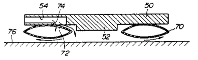
제3도, 제4도 및 제5a도 내지 제5c도에 나타난 바와 같이 복수개의 펠렛(50)은 프레임(12)의 하부 플레이트(12c)의 하부 표면에 고정되어 있다. 각각의 펠렛(50)은 평면으로 나타난 바와 같이 일정의 수직 두께와 정사각형을 갖는 수평 플레이트와 그의 저부에서 아래로 향하여 돌출되고 플로워(76)상에 정상적으로 안착되는 원추형 부분(52)으로 구성된다. 펠렛(50)은 유체를 통과시키기 위한 유체통로(54)를 가지며 유체통로(54)는 제4도에 나타난 바와 같이 유체공급 시스템에서 호오스(58)을 통해 유체원(56)으로 연결되어 있다. 펠렛(50)과 유체원(56) 사이에 커플러(60), 압력조절기(62), 밸브(64), 제한기(66), 긴급시 유체압력을 끊어주는 릴리이프 밸브(68)가 연결되어 있으며 이들 부품들은 유체공급 시스템을 구성한다. 유체공급 시스템은 본 발명에 직접적으로 관련이 없으므로 이를 상세히 기술하지 않는다. 탄성물질인 중공환부재(70)는 원추형 부분(52) 주위에 배치되어 있으며 유체통로(54)의 일측 단부에 출구(74)아래 일정의 개구(72)를 갖는다. 압력하의 공기와 같은 유체는 유체원(56)으로부터 유체통로(54)로 공급될때 공기는 개구(72)를 통해 각각 펠렛(50)의 환상 부재(70)로 공급하여 제5도에 나타난 바와 같이 환상 부재(70)를 부풀게 하여 원추 부분(72)을 플로워(76)에서 약간 들어 올린다. 압축공기가 환상 부재(70)내로 계속하여 공급되어 출구(74)와 환상 부재(70) 사이의 틈을 늘림으로써 공급된 공기가 틈을 통해 플로워(76)로 향하여 흐른다. 그 결과 유체층 또는 공기층은 플로워(76)와 환상 부재(70)의 저부사이에 진행하여 제5c도에 나타난 바와 같이 전 캐리지(10)을 들어 올린다. 환상 부재(70)와 플로워(76) 사이의 마찰계수가 전 캐리지(10)의 부동전에 제5a도 나타낸 조건에서 1/1000 내지 3/1000의 수준으로 감소된다. 따라서 캐리지(10)은 여기에 적용된 매우 적은 힘으로 움직일 수 있다.As shown in FIGS. 3, 4 and 5a to 5c, the plurality of
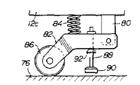
제3도, 제6a도 및 제6b도에서 예시한 바와 같이 하부 플레이트(12C)의 하부표면상에 브래키트(80)이 설치된다. 암(82)은 각각의 브래키트(80)의 하부 프리엔드에 추축으로 부착되어 있다. 압축 스프링(84)은 암(82)을 하방으로 정상적으로 누르기 위해 암(82) 및 하부 플레이트(12C) 사이에서 압축하에 배치된다. 캐리지(10)는 제6a도에 나타난 바와 같이 플로워(76)에서 부동될 때 암(82)은 압축 스프링(84)의 탄성하에 아래방향으로 눌러 회전하는 바퀴(86)가 암(82)의 말단 단부상에 설치되어 플로워(76)와 접촉하게 된다. 로드(88)는 암(82)을 통해 수직으로 연장되어 그의 하부 단부상에서 라버패드(90)를 지지한다. 반구형 부재(92)는 로드(88)의 중간부분에 고정된다. 캐리지(10)는 제6b도에 나타난 바와 같이 플로워(76)상까지 하강할 때 라버 패드(90)는 플로워(76)와 접촉하여 암(82)을 브래키드(80)의 피보트 핀(83)에서 상향으로 진동시켜 플로워(76)에서 바퀴(86)을 들어올리게 된다.As illustrated in FIG. 3, FIG. 6A and FIG. 6B, a
제7도는 가열로(94)에 인접하여 설치된 성형기의 프레임 어셈블리(96)를 나타낸다. 프레임 어셈블리(96)는 복수개의 수직 프레임(96a) 및 수직 프레임(96a)에 상부 단부에 고정된 상부 수평 플레이트(96b)로 구성된다. 실린더 유니트(98)는 상부 플레이트(96b)의 상부 표면상에 설치되어 있으며 지지 베이스(102)를 수직으로 이동하기 위한 상부 지지 베이스(102)의 연결부재에 커플링된 하부 단부를 갖는 로드(100)를 갖는다. 상부 지지 베이스(102)는 상부 부착 플레이트(38)를 그위에 설치된 상부 주형(44)으로 안전하게 물리게 하는 복수개의 클램프(104)를 갖는다.7 shows the
이하 부동 캐리지(10)의 조작을 기술한다. 새로운 상부 주형을 상부 부착 플레이트(38)에 부착하고 새로운 하부 주형을 하부 부착 플레이트(36)에 부착한다. 하부 주형을 적당한 서스펜션 장치로 하부 지지 베이스(20)상에 놓고 클램프(34)로 하부 지지 베이스(20)에 안전하게 고정한다. 그런다음 상부 부착 플레이트(38)를 동일한 서스펜션 장치로 하부 주형(42)위로 들어올리고 상부 및 하부 부착 플레이트(36), (38)를 콘넥팅로드(40)에 의해 상호 연결한다. 압축공기를 유체원(56)으로부터 각각의 환상 부재(70)내로 공급한다. 환상부재(70)는 부풀어 캐리지(10)를 플로워(76)로부터 들어 올린다. 그런다음 상당히 작은 힘으로 캐리지(10)에 가하여 캐리지(10)를 그대로 프레임 어셈블리(96)로 이동시킬 수 있다. 일정방향으로 고정하여 향하는 바퀴(86)로 캐리지(10)는 전술한 일정방향 이외의 다른 방향으로 이탈하는 것을 방지한다.The operation of the floating
캐리지(10)가 프레임 어셈블리(96)내에 놓여진 후 실린더 유니트(16)는 상부 부착 플레이트(38)가 상부 지지 베이스(102)에 대해 접촉될 때까지 하부 지지 베이스(20)를 올리는 작동을 한다. 상부 부착 플레이트(38)는 상부 지지 베이스(102)에 대해 놓여진 후 상부 부착 플레이트(38)는 클램프(104)로 상부 지지 베이스(102)를 고정한다. 그런다음 실린더 유니트(16)는 하부 지지 베이스(20)을 하강시키는 작동을 하고 콘넥팅로드(40)는 이동된다. 캐리지(10)는 제8도에 나타난 바와 같이 이때 프레임 어셈블리(96)내에 위치된다. 가열로(94)내에서 연화점까지 가열된 판유리를 캐리지(10)상에 설치된 리시버 플레이트(106)상에 공급 로울러(106)에서 수납된 후 판유리를 당분야의 공지의 방법으로 상부 및 하부 주형(42), (44) 및 링주형(32)에 의해 소정형상으로 구부러진다.After the
전술한 방법은 반대로 프레임 어셈블리(96)에서 주형(42), (44)을 제거하고 이를 새로운 주형으로 대체할 수 있다. 더 상세히는 실린더 유니트(16)를 하부 지지 베이스(20)를 들어 올리도록 작동하고 상부 및 하부 부착 플레이트(36), (38)를 콘넥팅 로드(40)로 서로 커플링한다. 클램프(104)는 바깥방향으로 진동하여 상부 부착 플레이트(38)을 상부 지지 베이스(102)로부터 풀어준다. 실린더 유니트(16)는 다시 하부 지지 베이스(102)를 하강하는 작동을 한다. 환상 부재(70)는 압축공기가 공급되어 캐리지(10)를 플로워로부터 뜨게 하고 캐리지(10)는 새로운 세트의 상부 및 하부 주형이 보관된 주형 보관소로 이동된다.The method described above can conversely remove the
비록 본 발명의 바람직한 구체예로 고려되는 것을 기술하였다 하더라도 본 발명의 필수적 특성을 떠나지 않고 다른 특이 형태로 구체화될 수 있음을 이해되어야 한다. 기재된 구체예는 본 발명을 예시하는 것이지 한정하는 것은 아니다. 본 발명의 범위는 전술한 기재에 의해서 보다 첨부된 특허청구의 범위에 의해 나타날 것이다.Although described as being preferred embodiments of the invention, it should be understood that they may be embodied in other specific forms without departing from the essential characteristics of the invention. The described embodiments illustrate, but do not limit, the present invention. It is intended that the scope of the invention be defined by the claims appended hereto further by the foregoing description.
Claims (5)
Applications Claiming Priority (3)
| Application Number | Priority Date | Filing Date | Title |
|---|---|---|---|
| JP62308973A JPH01148720A (en) | 1987-12-07 | 1987-12-07 | Floating die exchanging truck |
| JP62-308973 | 1987-12-07 | ||
| JP?62-308973 | 1987-12-07 |
Publications (2)
| Publication Number | Publication Date |
|---|---|
| KR890009776A KR890009776A (en) | 1989-08-04 |
| KR920000669B1 true KR920000669B1 (en) | 1992-01-20 |
Family
ID=17987444
Family Applications (1)
| Application Number | Title | Priority Date | Filing Date |
|---|---|---|---|
| KR1019880015416A KR920000669B1 (en) | 1987-12-07 | 1988-11-23 | Floating mold changer carriage |
Country Status (5)
| Country | Link |
|---|---|
| US (1) | US5087280A (en) |
| EP (1) | EP0320128B1 (en) |
| JP (1) | JPH01148720A (en) |
| KR (1) | KR920000669B1 (en) |
| DE (1) | DE3883177T2 (en) |
Families Citing this family (12)
| Publication number | Priority date | Publication date | Assignee | Title |
|---|---|---|---|---|
| JP3003132U (en) * | 1994-04-15 | 1994-10-18 | 東光金型有限会社 | Stick head for gateball |
| US6485247B1 (en) * | 2000-09-28 | 2002-11-26 | The Boeing Company | Engine uplift loader |
| JP4771270B2 (en) * | 2001-01-30 | 2011-09-14 | 旭硝子株式会社 | Method and apparatus for replacing glass plate mold |
| US7426974B1 (en) * | 2003-04-09 | 2008-09-23 | Yeghiayan Arra D | Air bearing base and workstation |
| SE528817C2 (en) | 2005-05-23 | 2007-02-20 | Camfil Ab | A pocket filter assembly |
| JP2007185638A (en) * | 2006-01-16 | 2007-07-26 | Akushii:Kk | Bag filter |
| CN102240753A (en) * | 2011-05-13 | 2011-11-16 | 厦门捷视光学有限公司 | Process for manufacturing metal glass frame body |
| US8800707B1 (en) * | 2011-08-23 | 2014-08-12 | The Boeing Company | Modular system and methods for moving large heavy objects |
| CN104550447B (en) * | 2015-01-26 | 2016-06-08 | 苏黎 | A kind of lower mold quick change construction of hot-riveting welding machine structure |
| CN108069583B (en) * | 2016-11-11 | 2019-12-27 | 比亚迪股份有限公司 | Curved glass hot bending die, curved glass and preparation method thereof |
| CN106584765A (en) * | 2016-11-18 | 2017-04-26 | 江苏智石科技有限公司 | Mold change trolley for self-adaption of lathe height |
| FI20185664A1 (en) * | 2018-07-31 | 2020-02-01 | Taifin Glass Machinery Oy | Method in a device for bending glass sheets, and device for bending glass sheets |
Family Cites Families (10)
| Publication number | Priority date | Publication date | Assignee | Title |
|---|---|---|---|---|
| US3457874A (en) * | 1966-09-19 | 1969-07-29 | Aida Iron Works & Co Ltd | Quick die changing system |
| US3618694A (en) * | 1969-10-06 | 1971-11-09 | Aero Go Inc | Hop-free fluid bearing of spandrel inflated flexible type |
| US3807035A (en) * | 1972-05-08 | 1974-04-30 | Ingersoll Milling Machine Co | Method of and apparatus for precision positioning of heavy workpieces |
| US3825094A (en) * | 1973-08-06 | 1974-07-23 | Rolair Syst Inc | Remote control for air bearing transporters and the like |
| JPS52118158A (en) * | 1976-03-26 | 1977-10-04 | Matsushita Electric Ind Co Ltd | V-belt and its preparation |
| US4082195A (en) * | 1976-06-21 | 1978-04-04 | Ex-Cell-O Corporation | Handling system for heavy loads |
| US4092141A (en) * | 1977-01-03 | 1978-05-30 | Ppg Industries, Inc. | Method and apparatus for handling glass sheets for shaping and cooling |
| US4273244A (en) * | 1979-01-29 | 1981-06-16 | Fmc Corporation | Crane upperstructure self-transferring system |
| JPS5749023U (en) * | 1980-09-03 | 1982-03-19 | ||
| JPS62182124A (en) * | 1986-02-03 | 1987-08-10 | Nippon Sheet Glass Co Ltd | Forming apparatus having mold changing device for flat glass |
-
1987
- 1987-12-07 JP JP62308973A patent/JPH01148720A/en active Granted
-
1988
- 1988-11-16 DE DE88310795T patent/DE3883177T2/en not_active Expired - Fee Related
- 1988-11-16 EP EP88310795A patent/EP0320128B1/en not_active Expired - Lifetime
- 1988-11-23 KR KR1019880015416A patent/KR920000669B1/en not_active IP Right Cessation
- 1988-12-07 US US07/402,898 patent/US5087280A/en not_active Expired - Fee Related
Also Published As
| Publication number | Publication date |
|---|---|
| US5087280A (en) | 1992-02-11 |
| DE3883177T2 (en) | 1993-12-23 |
| EP0320128A2 (en) | 1989-06-14 |
| DE3883177D1 (en) | 1993-09-16 |
| KR890009776A (en) | 1989-08-04 |
| JPH01148720A (en) | 1989-06-12 |
| EP0320128A3 (en) | 1990-09-05 |
| EP0320128B1 (en) | 1993-08-11 |
| JPH0545334B2 (en) | 1993-07-08 |
Similar Documents
| Publication | Publication Date | Title |
|---|---|---|
| KR920000669B1 (en) | Floating mold changer carriage | |
| FI84996C (en) | Method and apparatus for attaching, moving and adjusting sheets of flexible plastic material | |
| CA2151620C (en) | Flexible press | |
| CA2184397C (en) | Flexible press | |
| CA2135529C (en) | Flexible press rail support | |
| CN110479844B (en) | Bidirectional variable blank holder force deep drawing hydraulic press and use method thereof | |
| CN215378338U (en) | High strength communication support for communication engineering | |
| JPS5833578A (en) | Transferring device for vehicle body of automobile | |
| CN216229266U (en) | Double-station blanking stretching device | |
| CN210283578U (en) | Product lifting device applied to steel mesh printing equipment | |
| CN215515775U (en) | Module is transplanted in horizontal transport | |
| CN212712320U (en) | Curved surface glass's hoist device | |
| CN214646751U (en) | Device for cloth gold stamping | |
| CN217574129U (en) | Material pressing structure of aluminum foil gasket | |
| CN1128767C (en) | Apparatus and method for bending glass sheets | |
| CN220009130U (en) | Diaphragm printing positioning device | |
| CN215359441U (en) | Vulcanization device for production of wear-resistant engineering vehicle tire cushion belt | |
| CN219563921U (en) | Sponge conveying device for sponge vertical foaming machine | |
| CN217183558U (en) | Circuit board printing machine | |
| CN212658766U (en) | Full-automatic multiple operation processingequipment | |
| CN217333105U (en) | Oblique-pulling type clamping device | |
| CN216100409U (en) | Mechanical beating plate yarn wrapping mechanism | |
| CN213858815U (en) | Grinding wheel demolding equipment | |
| CN219740766U (en) | Portable mount pad is used to chip mounter | |
| CN220950191U (en) | Automatic cork pad pasting machine |
Legal Events
| Date | Code | Title | Description |
|---|---|---|---|
| A201 | Request for examination | ||
| G160 | Decision to publish patent application | ||
| E701 | Decision to grant or registration of patent right | ||
| GRNT | Written decision to grant | ||
| FPAY | Annual fee payment |
Payment date: 20030109 Year of fee payment: 12 |
|
| LAPS | Lapse due to unpaid annual fee |