KR910008972B1 - Internal combustion engine rotating position detector - Google Patents
Internal combustion engine rotating position detector Download PDFInfo
- Publication number
- KR910008972B1 KR910008972B1 KR1019880010420A KR880010420A KR910008972B1 KR 910008972 B1 KR910008972 B1 KR 910008972B1 KR 1019880010420 A KR1019880010420 A KR 1019880010420A KR 880010420 A KR880010420 A KR 880010420A KR 910008972 B1 KR910008972 B1 KR 910008972B1
- Authority
- KR
- South Korea
- Prior art keywords
- internal combustion
- combustion engine
- position detection
- sleeve member
- timing pulley
- Prior art date
Links
Images


Classifications
-
- G—PHYSICS
- G01—MEASURING; TESTING
- G01D—MEASURING NOT SPECIALLY ADAPTED FOR A SPECIFIC VARIABLE; ARRANGEMENTS FOR MEASURING TWO OR MORE VARIABLES NOT COVERED IN A SINGLE OTHER SUBCLASS; TARIFF METERING APPARATUS; MEASURING OR TESTING NOT OTHERWISE PROVIDED FOR
- G01D5/00—Mechanical means for transferring the output of a sensing member; Means for converting the output of a sensing member to another variable where the form or nature of the sensing member does not constrain the means for converting; Transducers not specially adapted for a specific variable
- G01D5/02—Mechanical means for transferring the output of a sensing member; Means for converting the output of a sensing member to another variable where the form or nature of the sensing member does not constrain the means for converting; Transducers not specially adapted for a specific variable using mechanical means
- G01D5/04—Mechanical means for transferring the output of a sensing member; Means for converting the output of a sensing member to another variable where the form or nature of the sensing member does not constrain the means for converting; Transducers not specially adapted for a specific variable using mechanical means using levers; using cams; using gearing
-
- F—MECHANICAL ENGINEERING; LIGHTING; HEATING; WEAPONS; BLASTING
- F02—COMBUSTION ENGINES; HOT-GAS OR COMBUSTION-PRODUCT ENGINE PLANTS
- F02P—IGNITION, OTHER THAN COMPRESSION IGNITION, FOR INTERNAL-COMBUSTION ENGINES; TESTING OF IGNITION TIMING IN COMPRESSION-IGNITION ENGINES
- F02P7/00—Arrangements of distributors, circuit-makers or -breakers, e.g. of distributor and circuit-breaker combinations or pick-up devices
- F02P7/06—Arrangements of distributors, circuit-makers or -breakers, e.g. of distributor and circuit-breaker combinations or pick-up devices of circuit-makers or -breakers, or pick-up devices adapted to sense particular points of the timing cycle
- F02P7/067—Electromagnetic pick-up devices, e.g. providing induced current in a coil
- F02P7/0677—Mechanical arrangements
Abstract
내용 없음.No content.
Description
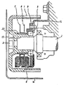
제1도는 이 발명의 한 실시예에 의한 내연기관용 회전위치 검출장치의 단면도.1 is a cross-sectional view of a rotation position detecting device for an internal combustion engine according to one embodiment of the present invention.
제2도는 그 회전위치 검출센서와 회전자의 관계를 표시하는 부분확대 단면도.2 is a partially enlarged cross-sectional view showing the relationship between the rotational position detection sensor and the rotor.
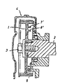
제3도는 이 발명의 다른 실시예에 의한 내연기관용 회전위치 검출장치의 단면도.3 is a cross-sectional view of a rotation position detecting device for an internal combustion engine according to another embodiment of the present invention.
제4도는 종래의 내연기관용 회전위치 검출장치의 단면도이다.4 is a cross-sectional view of a conventional rotational position detection apparatus for an internal combustion engine.
* 도면의 주요부분에 대한 부호의 설명* Explanation of symbols for main parts of the drawings
1 : 캠타이밍풀리 2 : 캠축1: Cam timing pulley 2: Cam shaft
3 : 고정나사 4 : 벨트덮개3: fixing screw 4: belt cover
5 : 베어링 6 : 회전위치 검출센서5: bearing 6: rotation position detection sensor
7, 8 : 회전자 13 : 슬리브7, 8: rotor 13: sleeve
그리고 각 도면중 동일부호는 동일 또는 상당부분을 표시한다.In the drawings, the same reference numerals indicate the same or corresponding parts.
이 발명은 내연기관의 회전위치를 검출하고 점화시기의 제어등에 사용하는 내연기관용 회전위치 검출장치에 관한 것이다.This invention relates to the rotation position detection apparatus for internal combustion engines used to detect the rotation position of an internal combustion engine, and to control the ignition timing.
제4도는 예를들면 일본국 실개소 60-23714호 공보에 공개된 종래의 내연기관용 회전위치 검출장치를 표시하는 단면도이다. 도면에서, 1은 캠타이밍풀리, 2는 풀리(1)가 장착되어 있는 캠축, 3은 풀리(1)를 고정하는 볼트, 4는 벨트덮개, 6은 기관본체축에 고착된 회전위치 검출센서, 7', 8'는 캠타이밍풀리(1)의 단면에 동축적 환상으로 설치된 리브이다.4 is a cross-sectional view showing a conventional rotational position detecting device for an internal combustion engine disclosed in, for example, Japanese Patent Application Laid-Open No. 60-23714. In the drawings, 1 is a cam timing pulley, 2 is a cam shaft on which the
리브(7'), (8')에는 슬릿이 있으며 이 슬릿이 회전위치 검출센서(6)를 통과할때에 캠축(2)의 회전각도위치에 따른 신호를 회전위치 검출센서(6)에서 출력한다. 상기와 같은 종래의 내연기관용 회전위치 검출장치에서는 회전위치 검출센서(6)를 먼저 기관본체측에 설치한 후 환상리브(7'), (8')가 있는 캠타이밍풀리(1)를 캠축(2)에 설치하는 것으로, 제부품의 제작정도에 기인하는 전반적인 내연기관용 회전위치 검출장치의 측정 정도는 실제의 조립을 완료하기까지 결정되지 못하며 내연기관용 회전위치 검출장치 단독으로 성능확인 및 보증을 할 수 없다는 결점이 있었다.The ribs 7 'and 8' have slits, and when the slits pass through the rotational position detection sensor 6, a signal corresponding to the rotational angle position of the
또 다른 부품의 결함에 의하여 캠타이밍풀리(1)등을 분리하여 재차 조립한 경우에 내연기관용 회전위치 검출장치의 정도가 변화되고 일정한 성능보증이 불가능하다는 결점이 있었다. 또한 캠타이밍풀리와 내연기관용 회전위치 검출장치를 개별적으로 취급하기 때문에 재고, 출하, 수송에서 기관본체의 조립에 이르기까지 많은 시간과 노력이 필요하였다.When the
이 발명은 그러한 결점을 제거하기 위한 것으로서, 내연기관용 회전위치 검출장치 단독으로 성능검사를 할 수 있고, 제조공장에서 보증부로 출하할 수 있는 내연기관용 회전위치 검출장치이며 또한 캠타이밍풀리에 조립되어 있는 것을 얻는 것을 목적으로 한다.The present invention is intended to eliminate such drawbacks, and is capable of performing a performance test by a rotating position detecting device for an internal combustion engine alone, and is a rotating position detecting device for an internal combustion engine that can be shipped to a guarantee unit in a manufacturing factory, and is assembled to a cam timing pulley. The purpose is to get something.
이 발명에 의한 내연기관용 회전위치 검출장치는 기관본체측에 고착되는 회전위치 검출센서 설치부재에 캠축을 통하게 하고 이와 함께 회전되는 슬리브부재를 회전가능하게 설치하며, 이 슬리브부재에 회전위치 검출센서와 협동하는 회전자를 장착하며 또한 슬리브부재를 캠타이밍풀리에 일체적으로 연결한 것이다.The rotation position detecting device for an internal combustion engine according to the present invention has a rotating position detecting sensor mounting member fixed to the engine main body via a camshaft and rotatably installs a sleeve member which is rotated together with the rotating position detecting sensor on the sleeve member. It is equipped with a cooperating rotor and the sleeve member is integrally connected to the cam timing pulley.
이 발명에서는 회전자와 회전위치 검출센서가 내연기관용 회전위치 검출장치로서 하나로 통합되고 있으므로 내연기관용 회전위치 검출장치 단독으로 성능확인을 할 수가 있다. 더구나 이 내연기관용 회전위치 검출 장치는 그 슬리브부재에 캠타이밍풀리와 일체적으로 구성되어 있으므로 캠타이밍풀리의 취급에 의하여 처리 될 수가 있다. 다음은 이 발명을 도면에 의하여 설명한다.In the present invention, since the rotor and the rotation position detection sensor are integrated into one rotation position detection device for the internal combustion engine, the performance check can be performed by the rotation position detection device for the internal combustion engine alone. Moreover, since the rotation position detecting device for the internal combustion engine is formed integrally with the cam timing pulley in the sleeve member, it can be processed by handling the cam timing pulley. Next, this invention is demonstrated by drawing.
제1도는 이 발명의 한 실시예에 의한 내연기관용 회전위치 검출장치를 표시하는 단면도이며, 1-4는 상기 종래의 것과 같다. 10은 이 발명의 내연기관용 회전위치 검출장치를 기관본체측에 지지하기 위한 고정암(arm), 9는 고정암(10)에 지지된 내연기관용 회전위치 검출장치의 설치부재, 6은 설치부재(9)에 설치된 회전위치 검출센서, 13은 설치부재(9)에 회전가능하게 장착된 슬리브부재, 5는 슬리브부재(13)를 설치부재(9)에 회전가능하게 보지하는 베어링, 7, 8은 슬리브부재(13)에 고착된 회전자이다. 이들 회전자(7), (8)은 그 주면에 슬릿이 파저있어 슬리브부재(13)의 회전에 따라 회전위치 검출센서(6)가 회전위치 신호를 출력하게 되어 있다.1 is a cross-sectional view showing a rotation position detecting device for an internal combustion engine according to an embodiment of the present invention, 1-4 is the same as the conventional one. 10 is a fixed arm for supporting the rotational position detecting apparatus for the internal combustion engine of the present invention on the engine body side, 9 is an installation member of the rotational position detection apparatus for the internal combustion engine supported by the
슬리브부재(13)는 캠축(2)에 느슨하게 덮혀있고 그 편평부(14)는 캠축(2)의 절삭부(14a)에 걸어맞추어 슬리브부재(13)를 캠축(2)의 회전에 추종시킨다. 그리고 11, 12는 파형와셔이다. 제2도는 회전위치 검출센서(6)와 회전자(7)의 관계를 예를들면 홀(hall)소자를 사용한 구체적예이다.The
도면에서, 15는 홀소자, 16은 자석, 17, 18은 연철제 자속카이드이다. 물론 이 경우 회전자(7)는 연철제와 같은 종류의 것이며 회전자(7)의 슬릿이 회전위치 검출센서(6)위치에 오면은 자석(16)의 자속이 홀소자(15)를 통하게 되어 있다. 그리고 제1도의 실시예에서는 설치부재(9)는 고정암(10)을 통하여 기관본체에 대하여 정지되어 있지만은 이와 같은 고정상태에 한정되는 것은 아니며 예를들어 기관본체측에서 캠축(2)에 평행으로 지주를 연장하고 이 지주가 통하는 구멍을 설치부재(9)에 설치하고 슬리브부재(13)를 캠축(2)에 장착시 설치부재(9)의 상기 구멍에 상기 지주를 통하게 하여 설치부재(9)의 회전을 지지하도록 하여도 된다.In the figure, 15 is a hall element, 16 is a magnet, and 17 and 18 are soft iron flux kides. Of course, in this case, the
이상의 설명에서 알 수 있는 바와 같이 이 발명의 내연기관용 회전위치 검출장치는 암(arm)상의 캠타이밍풀리(1)의 내측캠측(2)상에 장착되어 있다. 그리고 이 내연기관용 회전위치 검출장치는 종래것과 달리, 회전부와 정지부가 베어링(5)를 통하여 하나로 연결되어 있으므로 캠축(2)에 장착시에도 캠타이밍풀리(1)를 설치전에 이 내연기관용 회전위치 검출장치의 회전부(즉 슬리브부재(13))를 캠축(2)에 통하게 하여 그 정지부(즉 설치부재(9))를 고정암(10)등을 통하여 기관본체측에 설치하기만 하면 되므로 조립작업이 용이하게 된다.As can be seen from the above description, the rotation position detecting device for the internal combustion engine of the present invention is mounted on the
물론, 이 내연기관용 회전위치 검출장치는 기관본체에 조립하기전이라도 그 성능시험을 할 수가 있다. 또 캠축의 축 방향 진동에 대하여 이 내연기관용 회전위치 검출장치는 실질적으로 악영향을 받지 않는다. 왜냐하면은 슬리브부재(13)는 캠축(2)에 대하여 회전방향으로만 걸어 맞추어져 있고 축선방향에 대하여는 자유로이 되어 있기 때문이다.Of course, the rotation position detecting device for the internal combustion engine can be tested for its performance even before assembling to the engine main body. In addition, the rotation position detecting device for the internal combustion engine is substantially unaffected by the axial vibration of the camshaft. This is because the
제3도에서 제1도와 동일부분은 동일부호를 붙여서 그 설명은 생략한다. 이 실시예에서는 슬리브(13)에 캠타이밍풀리(1)가 일체적으로 형성되어 있다. 그리고 회전자(7), (8)는 관(20)을 통하여 슬리브부재(13)에 장착되어 있다. 따라서 이것은 캠타이밍풀리(1)를 캠축(2)에 설치하는 작업으로 내연기관용 회전위치 검출 장치도 장착되기 때문에 조립작업이 보다 능률화된다.In FIG. 3, the same parts as in FIG. 1 are denoted by the same reference numerals, and description thereof will be omitted. In this embodiment, the
이 발명은 이상 설명한 바와 같이 회전자(7), (8)를 갖추어 캠축과 함께 회전하는 회전부와 회전위치 검출 센서(6)를 구비하여 기관본체측에 고정되는 정지부가 베어링(5)를 통하여 하나로 연결되어 있으므로 종래와 같이 캠축(2)에 실제로 조립하지 않으면 그 측정정도를 알 수 없다는 일은 없으며 공장 출하시 보증부 출하를 할 수 있는 효과가 있다. 또한 캠타이밍풀리내의 유효공장을 활용하여 검출센서를 설치하였으므로 엔진을 컴펙트화하는 효과도 있다.As described above, the present invention includes a rotor (7) and a rotor (8) rotating together with the camshaft and a rotational position detecting sensor (6) so that a stationary part fixed to the engine body side is connected via a bearing (5). Since it is connected, the measurement accuracy is not known unless the assembly is actually assembled to the
Claims (1)
Applications Claiming Priority (6)
| Application Number | Priority Date | Filing Date | Title |
|---|---|---|---|
| JP1987170981U JPH0175815U (en) | 1987-11-09 | 1987-11-09 | |
| JP87-170981(U) | 1987-11-09 | ||
| JP??62-170981 | 1987-11-09 | ||
| JP62282552A JPH01124705A (en) | 1987-11-09 | 1987-11-09 | Rotational position detecting device for internal combustion engine |
| JP87-282552 | 1987-11-09 | ||
| JP?62-282552 | 1987-11-09 |
Publications (2)
| Publication Number | Publication Date |
|---|---|
| KR890008546A KR890008546A (en) | 1989-07-12 |
| KR910008972B1 true KR910008972B1 (en) | 1991-10-26 |
Family
ID=26493830
Family Applications (1)
| Application Number | Title | Priority Date | Filing Date |
|---|---|---|---|
| KR1019880010420A KR910008972B1 (en) | 1987-11-09 | 1988-08-17 | Internal combustion engine rotating position detector |
Country Status (4)
| Country | Link |
|---|---|
| US (1) | US4903525A (en) |
| KR (1) | KR910008972B1 (en) |
| DE (1) | DE3837870A1 (en) |
| FR (1) | FR2622925A1 (en) |
Families Citing this family (8)
| Publication number | Priority date | Publication date | Assignee | Title |
|---|---|---|---|---|
| CA1335641C (en) * | 1989-05-12 | 1995-05-23 | David E. Rawlings | Apparatus for positioning a sensor |
| US5408894A (en) * | 1993-03-09 | 1995-04-25 | Henson; Keith S. | Apparatus for mounting an object of interest on an electric motor |
| DE10023196C2 (en) * | 2000-05-11 | 2003-04-03 | Orenstein & Koppel Ag | Device for detecting the angle of rotation between two components |
| US6786084B2 (en) * | 2003-01-13 | 2004-09-07 | Delphi Technologies, Inc. | Sensor assembly and method for non-intrusively sensing instantaneous speed of the engine of a vehicle |
| US7296810B2 (en) * | 2004-04-01 | 2007-11-20 | Cnh America Llc | Apparatus and method for installing a sensor in connection with relatively movable members for sensing relative position thereof without adjustment |
| US7543831B2 (en) * | 2004-09-01 | 2009-06-09 | Cnh America Llc | Apparatus for installing a sensor on a kingpin |
| US7798015B2 (en) * | 2005-05-16 | 2010-09-21 | Endress + Hauser Flowtec Ag | Magneto-inductive flowmeter and measuring tube for such |
| FR2900701B1 (en) * | 2006-05-05 | 2008-08-01 | Skf Ab | DEVICE FOR CONTROLLING VALVES OF AN INTERNAL COMBUSTION ENGINE PROVIDED WITH AN INSTRUMENT BEARING |
Family Cites Families (7)
| Publication number | Priority date | Publication date | Assignee | Title |
|---|---|---|---|---|
| US3438362A (en) * | 1968-01-08 | 1969-04-15 | Willis D Clyborne | Ignition system |
| DE2363982A1 (en) * | 1973-12-21 | 1975-06-26 | Siemens Ag | IGNITION DISTRIBUTORS FOR IGNITION SYSTEMS IN COMBUSTION ENGINE |
| AT371603B (en) * | 1980-01-11 | 1983-07-11 | List Hans | ANGLE MARKER FOR DETERMINING THE TURNING ANGLE POSITION OF SHAFTS |
| SE452639B (en) * | 1984-12-20 | 1987-12-07 | Saab Scania Ab | ARRANGEMENTS FOR A COMBUSTION ENGINE FOR CONNECTING A DRUG SENSOR |
| DE3635756A1 (en) * | 1985-10-21 | 1987-04-23 | Honda Motor Co Ltd | ROTATIONAL SENSOR FOR AN INTERNAL COMBUSTION ENGINE |
| JPS63198740A (en) * | 1987-02-13 | 1988-08-17 | Fuji Heavy Ind Ltd | Crank angle detecting device for internal combustion engine |
| JP2745469B2 (en) * | 1992-03-13 | 1998-04-28 | ホクシン 株式会社 | Manufacturing method of ultra-thin fiberboard |
-
1988
- 1988-08-17 KR KR1019880010420A patent/KR910008972B1/en not_active IP Right Cessation
- 1988-11-08 DE DE3837870A patent/DE3837870A1/en active Granted
- 1988-11-09 FR FR8814616A patent/FR2622925A1/en active Granted
- 1988-11-09 US US07/269,092 patent/US4903525A/en not_active Expired - Lifetime
Also Published As
| Publication number | Publication date |
|---|---|
| KR890008546A (en) | 1989-07-12 |
| FR2622925B1 (en) | 1995-03-17 |
| FR2622925A1 (en) | 1989-05-12 |
| DE3837870A1 (en) | 1989-05-18 |
| US4903525A (en) | 1990-02-27 |
Similar Documents
| Publication | Publication Date | Title |
|---|---|---|
| KR910005480B1 (en) | Rotate position detecting device for engine | |
| KR910008972B1 (en) | Internal combustion engine rotating position detector | |
| US6323641B1 (en) | Non-contacting position sensor with helical flux linkage | |
| KR950007109Y1 (en) | Hall effect sensor with a protective support device | |
| WO2006020201A1 (en) | Offset magnet rotary position sensor | |
| JPH08254172A (en) | Rotation angle detecting device | |
| JPH02176481A (en) | Electromagnetic pickup | |
| JP2003172168A (en) | Mounting structure of plate for sensing crankshaft rotation angle | |
| US5528140A (en) | Rotation angle sensor for internal combustion engine having rotatable detection means | |
| WO2015075518A1 (en) | Camshaft, cam angle detection device, and internal combustion engine | |
| KR940006854Y1 (en) | Rotation swinkel detector | |
| DE4212973A1 (en) | Housing sealing cover for vehicle crankshaft - has sensor for determining speed or angle and ring for sealing lip functioning as pulse transmitter for sensor | |
| JPH01124705A (en) | Rotational position detecting device for internal combustion engine | |
| CN115263596A (en) | Engine | |
| US4620513A (en) | Rotational position detecting device for internal combustion engine | |
| KR930000025Y1 (en) | Distributor for internal combustion engine | |
| KR200165132Y1 (en) | Motor rotation velocity sensing unit | |
| US4903673A (en) | Iginition distributor for an internal combustion engine | |
| US4383442A (en) | Apparatus for sensing the presence and position of a crank pulley bolt in an internal combustion engine | |
| JPH09304008A (en) | Crank angle detector for engine | |
| JPH0544731Y2 (en) | ||
| KR100411039B1 (en) | An apparatus for measuring rotational position of a rotating shaft | |
| KR940002900Y1 (en) | Distributer | |
| JPH04104144U (en) | Engine crank angle detection device | |
| KR20020040248A (en) | A sensing system using a magnetic sensor |
Legal Events
| Date | Code | Title | Description |
|---|---|---|---|
| A201 | Request for examination | ||
| E902 | Notification of reason for refusal | ||
| G160 | Decision to publish patent application | ||
| E701 | Decision to grant or registration of patent right | ||
| GRNT | Written decision to grant | ||
| FPAY | Annual fee payment |
Payment date: 20021008 Year of fee payment: 12 |
|
| LAPS | Lapse due to unpaid annual fee |