KR910008536B1 - Ventilated and turns for rotor windings of a dynamoelectric machine - Google Patents
Ventilated and turns for rotor windings of a dynamoelectric machine Download PDFInfo
- Publication number
- KR910008536B1 KR910008536B1 KR1019870006398A KR870006398A KR910008536B1 KR 910008536 B1 KR910008536 B1 KR 910008536B1 KR 1019870006398 A KR1019870006398 A KR 1019870006398A KR 870006398 A KR870006398 A KR 870006398A KR 910008536 B1 KR910008536 B1 KR 910008536B1
- Authority
- KR
- South Korea
- Prior art keywords
- coolant gas
- rotor
- turns
- gas flow
- disposed
- Prior art date
Links
Images


Classifications
-
- H—ELECTRICITY
- H02—GENERATION; CONVERSION OR DISTRIBUTION OF ELECTRIC POWER
- H02K—DYNAMO-ELECTRIC MACHINES
- H02K1/00—Details of the magnetic circuit
- H02K1/06—Details of the magnetic circuit characterised by the shape, form or construction
- H02K1/22—Rotating parts of the magnetic circuit
- H02K1/32—Rotating parts of the magnetic circuit with channels or ducts for flow of cooling medium
-
- H—ELECTRICITY
- H02—GENERATION; CONVERSION OR DISTRIBUTION OF ELECTRIC POWER
- H02K—DYNAMO-ELECTRIC MACHINES
- H02K3/00—Details of windings
- H02K3/04—Windings characterised by the conductor shape, form or construction, e.g. with bar conductors
- H02K3/24—Windings characterised by the conductor shape, form or construction, e.g. with bar conductors with channels or ducts for cooling medium between the conductors
-
- H—ELECTRICITY
- H02—GENERATION; CONVERSION OR DISTRIBUTION OF ELECTRIC POWER
- H02K—DYNAMO-ELECTRIC MACHINES
- H02K3/00—Details of windings
- H02K3/04—Windings characterised by the conductor shape, form or construction, e.g. with bar conductors
- H02K3/22—Windings characterised by the conductor shape, form or construction, e.g. with bar conductors consisting of hollow conductors
Landscapes
- Engineering & Computer Science (AREA)
- Power Engineering (AREA)
- Windings For Motors And Generators (AREA)
- Motor Or Generator Cooling System (AREA)
Abstract
내용 없음.No content.
Description
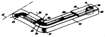
제1도는 본 발명에 따른 다이나모일렉트릭 머신의 회전자 권선의 사분면 단부 영역의 동축도.1 is a coaxial view of a quadrant end region of a rotor winding of a dynamoelectric machine according to the invention.
제2도는 제1도의 한 턴의 부분도.2 is a partial view of one turn of FIG.
제3도는 제1도의 다른 턴의 부분도.3 is a partial view of another turn of FIG.
* 도면의 주요부분에 대한 부호의 설명* Explanation of symbols for main parts of the drawings
10 : 본체부 11 : 회전자 권선10 main body 11 rotor winding
18 : 코일 슬로트 20, 30 : 콘덕터 또는 턴18: coil slot 20, 30: conductor or turn
24, 34 : 제1 및 제2가스 흐름 채널, 도관 또는 통로24, 34: first and second gas flow channels, conduits or passageways
28, 38 : 절연재 29, 39 : 제1 및 제2단부 턴28, 38: insulation material 29, 39: first and second end turn
본 발명의 일반적으로 다이나모일렉트머신의 회전자 권선에 관한 것으로, 특히, 권선의 단부 턴(turn)콘덕터를 환기시키기 위한 수단에 관한 것이다.The invention relates generally to the rotor windings of a dynamoelectric machine, and more particularly to means for venting the end turn conductors of the windings.
획일성 있고 쉬운 이해를 도모하기 위해, 본 명세서와 청구범위에 사용된 하기의 용어는 구체화된 의미를 갖는다. 기술적인 참고문헌이 항상 부합되지는 않고 내면적으로도 항상 일관된 것이 아님을 더 말할 나위도 없다. 콘덕터는 전기를 도전시키는 소자인데, 전형적으로 구리로 구성되며 전류 운반 통로의 다른 부재를 형성한다. 회전자의 폴 주위에서 하나의 전기적 루프가 턴이다. 코일은 회전자의 주변에서 예정된 축방향으로 연장하는 슬로트, 또는 코일 슬로트에 배치된 모든 턴을 구비한다. 권선은 회전자에서 모든 동심 코일을 구비한다.For the sake of uniform and easy understanding, the following terms used in the specification and claims have specific meanings. It goes without saying that technical references are not always consistent and are not always internally consistent. Conductors are devices that conduct electricity, typically consisting of copper and forming another member of the current carrying path. One electrical loop is turned around the pole of the rotor. The coil has a slot extending in a predetermined axial direction around the rotor, or all turns disposed in the coil slot. The winding has all the concentric coils in the rotor.
냉각가스 다이나모일렉트릭모신의 회전자는 다수의 코일이 배치된 다수의 축방향으로 연장하는 코일 슬포트를 규정하는 중앙 회전자 본체부를 포함한다. 슬로트는 동일한 폴부 주변에 배치된 모든 코일이 전형적으로 동심이 되고 회전자의 권선을 형성하도록 회전자 본체의 풀부의 한쪽면상의 회전자 본체의 주변에서 주변으로 이격된다.The rotor of the cooling gas dynamoelectric mossine includes a central rotor body portion defining a plurality of axially extending coil slits in which a plurality of coils are disposed. The slot is spaced around at the periphery of the rotor body on one side of the pull portion of the rotor body so that all coils disposed around the same pole are typically concentric and form the winding of the rotor.
다이나모일렉트릭머신에 쓰이는 전자계를 발생시키기 위하여, 권선을 구성하는 각각 다수의 콘덕터는 회전자 본체의 각 폴 둘레의 루프에서 전류를 운반한다. 콘덕터는 축방향으로 연장하며 각 턴 사이에 배치된 절연재 층이 있는 턴을 형성하도록 코일 슬로트에서 방사상으로 적층된다. 전류가 콘덕터에 흐를때, 콘덕터에서 I2R 손실에 의해 열이 발생된다. 비균일 온도 윤곽을 갖는 회전자 권선은 부분적으로 증강된 열팽창에 기인하여 더 높은 레벨의 열적 왜곡 및 진동을 받게되며, 결과적으로 이것은 균일한 온도 본포를 갖는 회전자 권선보다 더 낮은 레벨의 신빙성이 있다.In order to generate the electromagnetic field used in the dynamoelectric machine, each of the plurality of conductors constituting the winding carries current in a loop around each pole of the rotor body. The conductors are laminated radially in the coil slots to form turns with axially extending and layers of insulation disposed between each turn. When current flows through the conductor, heat is generated by the loss of I 2 R in the conductor. Rotor windings with non-uniform temperature contours are subject to higher levels of thermal distortion and vibration due to partially enhanced thermal expansion, which in turn has lower levels of reliability than rotor windings with uniform temperature shells. .
회전자 권선을 직접 냉각시키기 위한 많은 냉각구조는 콘덕터의 세로로난 도관에서 통로를 통해 냉각제 가스흐름을 사용하는 것이다. 그러나, 콘덕터의 세로 도관에서 흐르는 냉각제 가스를 도관의 길이를 따라 열을 취할때 온도가 증가되기 때문에, 길다란 냉각제 도관을 갖는 회전자 권선은 냉각제 가스 및 관련된 콘덕터의 커다란 열증가를 야기시킨다. 보충적인 냉각의 설비도 없이 냉각제 도관이 길면 길수록, 열점 온도, 즉, 극대 절대 온도는 더욱 커지며 코일의 평균 온도는 더 높아진다. 때로는 국부적인 열점은 열점 주변의 각 턴에서 제2도관을 위치시킴으로써 극소화된다. 그러나 소정의 회전자 권선을 설계할 때 턴을 형성하는 콘덕터는너무 협소하여 동일한 턴에서 두개의 홈을 수용할 수가 없다.Many cooling schemes for direct cooling of the rotor windings use coolant gas flow through the passages in the longitudinal conduits of the conductors. However, because the temperature increases as the coolant gas flowing in the longitudinal conduit of the conductor heats up along the length of the conduit, the rotor winding with a long coolant conduit causes a large thermal increase in the coolant gas and associated conductors. The longer the coolant conduit without the provision of supplemental cooling, the higher the hot spot temperature, i.e. the maximum absolute temperature, and the higher the average temperature of the coil. Sometimes local hot spots are minimized by placing the second conduit on each turn around the hot spots. However, when designing a given rotor winding, the conductor that forms the turn is too narrow to accommodate two grooves in the same turn.
공지된 냉각구조에 있어서, 냉각제 가스는 폴 중심선 근방의 단일 채널로 유입되며 턴 모퉁이를 통하여 회전자 본체를 향하여 흐른다. 방사상으로 외부 턴 및 방사상으로 인접한 내부 턴에서 상기 호름은 두 턴의 방사상 외부턴에 배치된 단일 채널에서 합류된다. 방사상 내부 턴으로부터의 가스는 회전자 본체의 축 단부 바로 외면에 위치한 턴 절연체 및 구리 코일내의 홀을 통해 방사상 외부턴의 가스흐름과 합류한다. 그때 새로운 냉각제 가스는 두개의 외면에서 가스 흐름이 합류되는 위치에서 방사상 내부턴 바로 내면으로 유입된다.In known cooling arrangements, coolant gas enters a single channel near the pole centerline and flows through the turn corners towards the rotor body. On radially outer turns and radially adjacent inner turns, the horns join in a single channel disposed on two turns of radial outer turns. The gas from the radial inner turn joins the gas flow of the radial outer turn through a hole in the copper coil and a turn insulator located just outside the axial end of the rotor body. The new coolant gas then enters the inner surface immediately following the radial inner turn at the location where the gas flows join at the two outer surfaces.
또 다른 구조는 코일의 축방향으로 놓인 기반부 및 코일의 주변 단부에 배치된 분리 내부통로를 포함한다. 주변 단부에서 가스 흐름은 정교하고 값비싼 차폐장치구조에 의해 축방향으로 놓인 콘덕터에서 가스가 분류되는 것이 방지된다. 냉각제 가스는 다이나모일렉트릭머신의 폴면 또는 중심링을 통해 방출될 수도 있다. 차단작용은 콘덕터에서 내부 통로를 통해 냉각제 가스 흐름을 촉진시키는 적당한 가스 압력차를 유지하기 위하여 서로가 비교적 가깝게 배치된 가스 입구 및 가스 출구를 갖는 권선 냉각제 시스템용으로도 요구된다.Another structure includes an axially laid base of the coil and a separate inner passage disposed at the peripheral end of the coil. The gas flow at the peripheral end is prevented from fractionating the gas in the axially placed conductors by the sophisticated and expensive shielding structure. The coolant gas may be released through the pole face or the center ring of the dynamoelectric machine. Shutoff is also required for winding coolant systems having gas inlets and gas outlets disposed relatively close to each other to maintain a suitable gas pressure differential that promotes coolant gas flow through the internal passageway in the conductor.
따라서, 본 발명의 목적은 다이나모일렉트릭머신의 회전자 권선의 냉각을 제공하는 것으로, 회전자 권선은 인접하게 배치된 두개의 가스 통로를 수용할 수 없는 협소한 턴을 포함한다.It is therefore an object of the present invention to provide cooling of the rotor windings of a dynamoelectric machine, the rotor windings comprising a narrow turn that cannot accommodate two gas passages arranged adjacently.
본 발명의 다른 목적은 회전자 권선의 단부 턴에서 실제로 균일한 온도 윤곽을 유지시키는 것이다.Another object of the present invention is to maintain a substantially uniform temperature profile at the end turns of the rotor windings.
본 발명의 다른 목적은 다이나모일렉트릭머신의 폴면 또는 중심링을 통해 냉각제 가스를 방출하는 환기구조에서 요구된 것과 같은 차단 장치의 필요를 제거시키는 것이다.Another object of the present invention is to eliminate the need for a shutoff device such as that required for a ventilation structure that releases coolant gas through the pole face or center ring of a dynamoelectric machine.
본 발명에 따라, 다이나모일렉트릭머신용 회전자는 폴부 및 회전자 권선의 한쪽면의 본체의 주변에서 주변으로 이격된 축 권선 슬로트를 규정하는 본체부를 구비한다. 회전자 권선은 권선 슬로트에 배치된 축방향으로 연장하는 다수의 제1슬로트 기반 콘덕터 및 회전자 본체를 지나서 연장하는 다수의 제1단부 턴을 포함한다. 다수의 제1단부 턴은 다수의 제1슬로트 기반 콘덕터의 확장에 의해 형성된 다수의 제1축단부 턴 콘덕터 및 다수의 제1축단부 턴 콘덕터에 각기 접속하는 다수의 제1단부 턴 주변 콘덕터를 포함한다. 회전자 권선은 권선 슬로트에 배치된 축방향으로 연장하는 다수의 제2슬로트 기반 콘덕터도 포함하며, 상기 다수의 제2슬로트 기반 콘덕터의 각각은 다수의 제1슬로트 기반 콘덕터의 인접한 콘덕터와 전기적으로 절연되어 있다. 다수의 제2단부 턴은 회전자 본체를 지나서 연장하며 다수의 제1단부 턴과 교대로 배치된다. 다수의 제2단부 턴의 각각을 열 흐름 전달을 하는 다수의 제1단부턴의 인접한 턴과 전기적으로 절연된다. 다수의 제2단부 컨은 다수의 제2슬로트 기반 콘덕터의 확장에 의해 형성된 다수의 제2축 단부 턴 콘덕터를 포함하며, 상기 다수의 제2축 단부 턴 콘덕터에 각기 접속하는 다수의 제2단부 턴 주변 콘덕터도 포함한다. 다수의 제1단부 턴은 다수의 제1단부 턴을 따라 세로로 연장하는 다수의 제1냉각제 가스흐름 태널을 포함하며, 상기 다수의 제1냉각제 가스 채널은 다수의 제1단부 턴 주변 콘덕터에 각기 배치된 다수의 각각의 제1냉각제 가스 입구를 가지고 있다. 다수의 제2단부 턴은 다수의 제2단부 턴을 따라 세로로 연장하는 각기 다수의 제2냉각제 가스 흐름 채널을 포함하며, 상기 다수의 제2냉각제 가스 채널은 다수의 제2축 단부 턴 콘덕터에 각기 배치된 각각의 다수의 제2냉각제 가스 입구를 가지고 있다.In accordance with the present invention, a rotor for a dynamoelectric machine includes a pawl portion and a body portion defining an axial winding slot spaced from the periphery of the body on one side of the rotor winding. The rotor winding includes a plurality of axially extending first slot based conductors disposed in the winding slot and a plurality of first end turns extending beyond the rotor body. The plurality of first end turns comprise a plurality of first end turns each connected to a plurality of first end turn conductors and a plurality of first end turn conductors formed by the expansion of the plurality of first slot based conductors. Includes peripheral conductors. The rotor winding also includes a plurality of second slot based conductors extending axially disposed in the winding slots, each of the plurality of second slot based conductors being a plurality of first slot based conductors. It is electrically insulated from adjacent conductors. The plurality of second end turns extend beyond the rotor body and are alternately arranged with the plurality of first end turns. Each of the plurality of second end turns is electrically insulated from adjacent turns of the plurality of first end turns for heat flow transfer. The plurality of second end cones comprises a plurality of second axis end turn conductors formed by the expansion of the plurality of second slot based conductors, the plurality of second end cones respectively connecting to the plurality of second axis end turn conductors. It also includes a conductor around the second end turn. The plurality of first end turns includes a plurality of first coolant gas flow channels extending longitudinally along the plurality of first end turns, wherein the plurality of first coolant gas channels are connected to the plurality of first end turns peripheral conductors. Each has a plurality of respective first coolant gas inlets arranged. The plurality of second end turns includes a plurality of second coolant gas flow channels each extending longitudinally along the plurality of second end turns, the plurality of second coolant gas channels each comprising a plurality of second axial end turn conductors. Each has a plurality of second coolant gas inlets disposed therein.
다수의 제1냉각제 가스 입구는 회전자 폴부의 중심선 근방에 배치될 수 있으며, 그리고 다수의 제2냉각제 가스 입구는 다수의 제2단부 턴 주변 콘덕터 및 다수의 축단부 턴 콘덕터의 접합부에서 모서리 근방에 배치될 수 있다. 그러므로, 다수의 제1냉각제 가스 입구부의 회전자 본체의 축 단부까지 전개된 길이는 다수의 제2냉각제 가스 입구부터 회전자 본체의 축 단부까지 전개된 길이보다 더 길다. 또한, 단부 턴들 사이에 배치된 절연재는 다수의 제1 및 제2가스 흐름 채널의 표면을 형성할 수 있다.The plurality of first coolant gas inlets may be disposed near the center line of the rotor poles, and the plurality of second coolant gas inlets may be edged at the junction of the plurality of second end turn peripheral conductors and the plurality of axial end turn conductors. It can be placed in the vicinity. Therefore, the length developed from the plurality of second coolant gas inlets to the shaft end of the rotor body is longer than the length developed from the plurality of second coolant gas inlets to the shaft end of the rotor body. In addition, the insulation disposed between the end turns can form the surface of the plurality of first and second gas flow channels.
신규한 것으로 인식된 본 발명의 특징은 첨부된 청구범위에서 구체적으로 설명된다. 그러나, 또 다른 목적 및 장점과 함께, 작동 방법 및 구성으로서의 본 발명의 그 자체는 첨부된 도면에 관하여 취해진 상세한 설명을 참조함으로서 명백히 이해될 것이다.Features of the invention that are recognized as novel are specifically described in the appended claims. However, together with other objects and advantages, the invention itself as a method of operation and construction will be clearly understood by reference to the detailed description taken in conjunction with the accompanying drawings.
제1도를 참조하면, 다이나모일렉트릭머신의 사분면의 단부 턴 영역에 대한 등축도가 도시되었다. 다이나모일렉트릭머신은 회전자의 폴(pole)부 (12)양측면에서 회전자 본체부(10)의 주변에서 원형으로 이격된 축 코일 솔로트(18)를 한정하는 중앙 본체부(10)를 구비한다. 단부 턴 영역이 폴면 중심(15)에 대하여 대칭이며, 그리하여 불필요한 반복을 피하기 위해, 본 발명을 이해하는데 통상의 지식을 가진 자에게 필요한 단부 턴 영역만이 도시되었다.Referring to FIG. 1, an isometric view of the end turn area of the quadrant of the dynamoelectric machine is shown. The dynamoelectric machine has a central body portion 10 defining a shaft coil sole 18 spaced in a circle around the rotor body portion 10 on both sides of the pole portion 12 of the rotor. . The end turn areas are symmetrical with respect to the pole face center 15, so that only the end turn areas necessary for those skilled in the art to understand the present invention are shown in order to avoid unnecessary repetition.
회전자 권선(11)은 콘덕터 각각의 방사상 외부 표면에 걸쳐 배치된 절연체(28, 38)층을 갖는 교대로 적층된 다수의 콘덕터 (20,30)를 구비한다. 도시된 각 턴의 단일 콘덕터를 포함하기 때문에, "콘덕터" 및 "턴"이란 용어는 상호 교환 가능하게 사용될 수도 있다. 그러나, 본 발명은 복수의 콘덕터 턴이 유익하게 이용될 수도 있다. 방사상으로 최외곽, 또는 상단 턴(40)은 방사상으로 절연재(38)층 바깥쪽으로 배치되며 절연재(14)층은 방사상으로 상단 턴(40) 바깥쪽으로 배치된다. 방사상 외부 표면에 배치된 절연채(44)층을 갖는 방사상으로 가장 안쪽, 또는 하단 턴(42)은 방사상으로 가장 안쪽으로 배치된 턴(20)으로부터 방사상으로 안쪽으로 위치된다. 턴(20,30,40,42)은 설명할 냉각용 설비를 제외하고는 유사하게 제조될 수도 있다. 정형적으로 슬로트 웨지(도시않됨)는 슬로트(28)내의 권선(11)을 고착시키기 위해 절연재(14)층 외부에서 방사상으로 배치된다. 또한 권선(11)과 비슷하게 제조될 수 있는 권선의 다른 권선(19)이 도시되었다.The rotor winding 11 has a plurality of conductors 20, 30 alternately stacked with layers of insulators 28, 38 disposed over the radially outer surface of each conductor. As it includes a single conductor of each turn shown, the terms "conductor" and "turn" may be used interchangeably. However, in the present invention, a plurality of conductor turns may be advantageously used. The radially outermost, or top, turn 40 is disposed radially outward of the layer of insulation 38 and the layer of insulation 14 is disposed radially outward of the upper turn 40. The radially innermost, or bottom turn, 42 with a layer of insulation 44 disposed on the radially outer surface is located radially inward from the radially innermostly disposed turn 20. Turns 20, 30, 40, and 42 may be similarly manufactured, with the exception of the cooling arrangements described. A slot wedge (not shown) is typically disposed radially outside the layer of insulation 14 to secure the winding 11 in the slot 28. Also shown is another winding 19 of the winding that can be manufactured similar to winding 11.
턴(20)은 코일 슬로트(18)에 배치된 축방향으로 연장하는데 제1슬로트 기반부(25)와 제1단부 턴(29)을 포함한다. 제1단부 턴(29)은 제1슬로트 기반부(25)의 확장으로 형성된 제1단부 턴 축부(23)와 제1단부 턴 축부(23)에 결합된 단부 턴 주변부(21)를 포함한다. 유사하게 턴(30)은 코일 슬로트(18)에 배치된 축방향으로 연장하는 제2슬로트 기반부(25)와 제2단부 턴(39)을 포함한다. 제2단부 턴(39)을 제2슬로트 기반부(35)의 연장에 의해 형성된 제2단부 턴 축부(33)와 제2단부 턴 축부(33)에 결합된 단부 턴 주변부(31)를 포합한다. 제2단부 턴(39)은 제1단부 턴(29)과 교대로 배치되며 제1 및 제2단부 턴(39)은 제1단부 턴(29)과 교대로 배치되며 제1 및 제2단부 턴(29,39)중의 인접한 턴은 상호 열 흐름통로 배치된다. 턴(20,30,40,42)은 본 기술에서 공지된 바와 같이 회전자 본체(10)와 적합하게 전기적으로 절연된다(도시않음).The turn 20 extends in an axial direction disposed in the coil slot 18 and includes a first slot base 25 and a first end turn 29. The first end turn 29 includes a first end turn shaft 23 formed by the expansion of the first slot base 25 and an end turn perimeter 21 coupled to the first end turn shaft 23. . Similarly, the turn 30 includes an axially extending second slot base 25 and a second end turn 39 disposed in the coil slot 18. The second end turn 39 includes a second end turn shaft 33 and an end turn periphery 31 coupled to the second end turn shaft 33 formed by the extension of the second slot base 35. Add up. The second end turn 39 is alternately arranged with the first end turn 29, and the first and second end turns 39 are alternately arranged with the first end turn 29 and the first and second end turns 29. Adjacent turns in (29, 39) are arranged in mutual heat flow paths. Turns 20, 30, 40, 42 are suitably electrically insulated from rotor body 10 as is known in the art (not shown).
제2도를 참조하면, 콘덕터 또는 턴(20)의 일부가 도시되었다. 콘덕터(20)는 그안에서 세로의 제1가스흐름 채널(24)을 규정하기 위한 제1냉각제 가스 출구(26)를 포함한다. 제1가스 흐름 채널(24)은 콘덕터(20)에 의해 완전히 에워싸이지는 않고 제1가스 흐름 채널(24)의 제1냉각제 가스 입구(22)에서 제1가스 흐름 채널(24)의 제1냉각제 가스 출구(26)로 가스 흐름을 유도하기 위한 도관을 형성하도록 가로 놓인 절연재(28)에 의해 둘러싸인다. 제1냉각제 가스 출구(26)는 콘덕터(20)와 가로 놓인 절연재(28)층을 통해 방사상으로 지향된 홀(hole)을 포함한다. 제1가스 흐름 채널(24)의 제1냉각제 가스 입구(22) 또는 제1가스 흐름 채널(24)과 교차하지 않도록 표면 중심(15)과 이격된 채로 폐쇄된다.Referring to FIG. 2, a portion of the conductor or turn 20 is shown. Conductor 20 includes a first coolant gas outlet 26 for defining a longitudinal first gas flow channel 24 therein. The first gas flow channel 24 is not completely enclosed by the conductor 20 and the first of the first gas flow channel 24 at the first coolant gas inlet 22 of the first gas flow channel 24. Surrounded by insulating material 28 laid down to form a conduit for directing gas flow to the coolant gas outlet 26. The first coolant gas outlet 26 comprises a hole directed radially through the layer of insulation 28 which intersects the conductor 20. It is closed spaced from the surface center 15 so as not to intersect the first coolant gas inlet 22 or the first gas flow channel 24 of the first gas flow channel 24.
제3도를 참조하면, 콘덕터 또는 턴(30)의 일부가 도시되었다. 콘덕터(30)는 그안에서 세로의 가스 흐름 채널을 규정하는 제2냉각제 가스 출구(36)를 포함한다. 제2가스 흐름 채널(34)은 제2가스 흐름 채널(34)과 협동하여 가로놓인 절연재(38)층이 가스 운반 도관을 형성하도록 콘덕터(30)로 완전히 둘러싸이지 않는다. 실제로 제2가스 흐름 채널(34)은 단부 턴 축부(33)에 배치되며 축방향 내측 폴면을 제2가스 흐름 채널(34)의 제2냉각제 가스 출구(36)까지 연장시킨다. 제2냉각제 가스 출구(36)는 콘덕터(30) 및 가로놓인 절연재(38)를 통해 일반적으로 방사상으로 연장하는 홀을 포함하여, 콘덕터(20), (제2도) 및 콘덕터(30)가 코일 슬로트(18),(제2도)에 적합하게 배치될 때, 제1냉각제 가스 출구(26),(제2도) 및 제2냉각제 가스 출구(36)가 일반적으로 방사상으로 연장하는 굴뚝(16)을 형성하도록 일치된다. 굴뚝(16)은 다이나모일렉트릭머신의 고정자(도시 안됨) 및 회전자 본체부(10)사이의 간격으로 배출되도록 제1가스 흐름 채널(24)의 제1냉각제 가스 입구(22) 및 제2가스 흐름 채널(34)의 제2냉각제 가스 입구(32)로 들어가는 가스 흐름을 조종한다. 제2냉각제 가스 입구(32)는 콘덕터(30)의 측면에 배치되어 콘덕터(30)의 모서리(37)와 회전자 본체부(10)의 축단부(13)(제1도)사이에서 축방향으로 이격된다. 제2냉각제 가스 입구(32)는 모서리(37)의 기계적이며 구조적인 일체성을 이루지 않고 콘덕터(30)의 모서리(37)와 가능하면 밀접하게 이격된다.Referring to FIG. 3, a portion of the conductor or turn 30 is shown. Conductor 30 includes a second coolant gas outlet 36 defining a longitudinal gas flow channel therein. The second gas flow channel 34 is not completely enclosed by the conductor 30 such that the layer of insulating material 38 which cooperates with the second gas flow channel 34 forms a gas delivery conduit. In fact, the second gas flow channel 34 is disposed in the end turn shaft 33 and extends the axially inner pole surface to the second coolant gas outlet 36 of the second gas flow channel 34. The second coolant gas outlet 36 includes a hole that extends generally radially through the conductor 30 and the intersecting insulation 38, so that the conductor 20, (FIG. 2) and the conductor 30 ) Is suitably disposed in the coil slot 18, (FIG. 2), the first coolant gas outlet 26, (FIG. 2) and the second coolant gas outlet 36 generally extend radially. To match the chimney 16. The chimney 16 is the first coolant gas inlet 22 and the second gas flow of the first gas flow channel 24 to be discharged at an interval between the stator (not shown) of the dynamo electric machine and the rotor body portion 10. It directs the gas flow entering the second coolant gas inlet 32 of the channel 34. The second coolant gas inlet 32 is disposed on the side of the conductor 30 between the edge 37 of the conductor 30 and the shaft end 13 (FIG. 1) of the rotor body 10. Spaced axially. The second coolant gas inlet 32 is possibly as close as possible to the edge 37 of the conductor 30 without achieving mechanical and structural integrity of the edge 37.
콘덕터(20 및 30)는 이를테면 콘덕터(24)로 포함하는 교대 턴에서, 차가운 냉각제 가스가 제1냉각제 가스 입구(22)에서 제1가스 흐름 채널(24)로 인입하도록 교대로 적층된다. 콘덕터(30)를 포함하는 턴에 대하여, 차가운 냉각제 가스는 제2냉각제 가스 입구(32)에서 제2가스 흐름 채널(34)로 인입한다. 코일의 각 사분면에 대하여, 모든 제1 및 제2가스 흐름 채널(24,34)은 회전자 본체부(10)의 축단부의 내측에 배치된 각각의 공통 굴뚝(16)으로 방출된다. 화살표(17), (제1도)는 굴뚝(16)으로 부터의 가스 흐름 방향을 나타낸다.Conductors 20 and 30 are alternately stacked such that, in alternating turns, including conductor 24, cold coolant gas enters first gas flow channel 24 at first coolant gas inlet 22. For the turn comprising the conductor 30, cold coolant gas enters the second gas flow channel 34 at the second coolant gas inlet 32. For each quadrant of the coil, all the first and second gas flow channels 24, 34 are discharged to respective common chimneys 16 arranged inside the shaft ends of the rotor body 10. Arrows 17 and 1 show the gas flow direction from the chimney 16.
제1도에 도시된 실시예에서, 상부 턴(40) 및 하부 턴(42)이 냉각제 통로 또는 도관을 포함하지 않음을 주목하자. 그러나, 냉각제 통로는 원한다면 상부 턴(40) 및 하부 턴(42)의 양쪽 또는 한쪽에 제공될 수도 있다. 또한, 단부 턴 영역에서 콘덕터(20 및 30)의 적층순서는 예를 들어, 콘덕터(30)를 하부 턴(42)의 방사상 바로 외부에 배치시켜 콘덕터(20 및 30)가 교대로 적층되게 하는 바와 같은 제1도에 도시된 순서로 변경될 수 있다. 또한, 단부 지역내로 냉각제 가스의 흐름을 조절하거나 다이나모일렉트릭머신의 제1 및 제2가스 흐름 채널(24,34)내로 냉각제 가스 흐름을 가압하기 위한 어떠한 차단 장치도 요구되지 않음이 제1도에서 관찰될 수 있다.Note that in the embodiment shown in FIG. 1, the upper turn 40 and the lower turn 42 do not include coolant passages or conduits. However, coolant passages may be provided on both or one side of upper turn 40 and lower turn 42 if desired. In addition, the stacking order of the conductors 20 and 30 in the end turn region, for example, the conductors 30 and 30 are alternately stacked by placing the conductors 30 just outside the lower turn 42. It may be changed in the order shown in FIG. It is also observed in FIG. 1 that no shutoff device is required to regulate the flow of coolant gas into the end region or to pressurize the coolant gas flow into the first and second gas flow channels 24 and 34 of the dynamoelectric machine. Can be.
본 발명의 콘덕터(20)와 유사한 콘덕터를 갖는 종래의 냉각 구조에 있어서, 두 개가 나란히 세로로 연장하는 가스 흐름 채널이 유사 콘덕터의 축 단부 턴부에 배치되어 유사 콘덕터의 축 단부 턴부에 배치된 제2채널로 유입될 수 있다. 그러나, 본 발명은 냉각 단부 턴을 향해 지향되어 있으며 여기에서 콘덕터는 동일한 콘덕터에서 두 병행 냉각제 가스 통로를 지탱하기에 충분한 크기로 구성되어 있지 않으며, 상기 통로는 콘덕터를 통해 필요한 냉각제 가스 흐름을 제공하기에 적당한 크기를 가지면서도 다이나모일렉트릭머신의 적절한 작동에 필요한 콘덕터의 구조적인 통합을 그대로 유지하고 있다.In a conventional cooling structure having a conductor similar to the conductor 20 of the present invention, two side-by-side longitudinally extending gas flow channels are disposed in the axial end turn of the similar conductor so that the axial end turn of the similar conductor is provided. Can flow into the second channel disposed. However, the present invention is directed towards a cooling end turn where the conductors are not configured to be large enough to support two parallel coolant gas passages in the same conductor, the passages passing the required coolant gas flow through the conductors. It is sized to provide and maintains the structural integration of the conductors required for proper operation of the dynamoelectric machine.
작동중에, 냉각제 가스는 제1냉각제 가스 입구(22)에서 콘덕터(20)의 제1가스 흐름 채널(24)로 유입한다. 냉각제 가스가 콘덕터(20)의 주변부(21)의 제1가스 흐름 채널(24)을 따라 흐르기 때문에 콘덕터(20)로부터 열을 제거시키며 또한 방사상으로 콘덕터(20) 내부 및 외부에 각기 배치된 인접 콘덕터(30)로부터 열을 제거시킨다. 콘덕터(20)의 제1가스 흐름 채널(24)을 통해 흐르는 냉각제 가스에 의한 콘덕터(30)의 주변부(31)로부터의 열의 제거는 콘덕터(30)로부터 절연재(28 또는 38)을 통해 열이 흐르는 것이 요구된다. 절연재(28,38)의 두께가 각기 약 0.025cm(0.010인치) 내지 0.050cm(0.020인치), 양호하게는 약 0.038cm(0.015인치)라면 적합한 열유동이 얻어질 수 있다는 것을 알고 있다. 절연재(28,38)는 직조된 폴리에스터 유리 물질 또는 다른 종래의 전기적 절연물질을 각기 포함할 수도 있는데, 이것은 상술한 두께 및 적용에 대한 물질의 열 전달 특성이 현저히 가변하지 않으며 콘덕터(30)의 주변부(31)의 소절의 온도 윤곽을 유지시키기 위한 적합한 열 전달을 결정할 수가 있는 것이다.In operation, coolant gas enters the first gas flow channel 24 of the conductor 20 at the first coolant gas inlet 22. Since coolant gas flows along the first gas flow channel 24 of the perimeter 21 of the conductor 20, it removes heat from the conductor 20 and is disposed radially inside and outside the conductor 20, respectively. Heat is removed from the adjacent adjacent conductors 30. The removal of heat from the periphery 31 of the conductor 30 by the coolant gas flowing through the first gas flow channel 24 of the conductor 20 results from the conductor 30 through the insulation material 28 or 38. Heat is required to flow. It is understood that suitable heat flow can be obtained if the thickness of the insulation materials 28 and 38 are each about 0.025 cm (0.010 inch) to 0.050 cm (0.020 inch), preferably about 0.038 cm (0.015 inch). Insulation materials 28 and 38 may each comprise a woven polyester glass material or other conventional electrical insulating material, which does not significantly vary the heat transfer properties of the material for the above-described thicknesses and applications and the conductor 30 It is possible to determine a suitable heat transfer for maintaining the temperature profile of the measures of the periphery 31.
비록 제1냉각제 가스 입구(22)로 유입하는 냉각제 가스가 비교적 차가울지라도, 이 가스의 온도는 제1가스 흐름 채널(24)을 따라 흐르는 동안 열을 취한 만큼 상승되어, 가스가 턴 모서리(27)에 도달하는 시간까지 그 냉각 효과를 많이 잃을 수도 있다. 모서리(27)로부터의 회전자(10) 본체를 향해 축 내부로 흐르는 가스의 냉각 효과의 손실을 상쇄시키기 위해, 콘덕터(30)의 제2가스 흐름 채널(34)의 제2냉각제 가스 입구(32)로 비교적 차가운 냉각재 가스의 새로운 공급이 수행된다. 콘덕터(30)의 채널에서 흐르는 냉각제 가스는 콘덕터(30)에서 일소된 열을 제거하며 또한 방사상으로 콘덕터(30)의 바로 내부 및 외부에 배치된 콘덕터(30)에서 일소된 약간의 열을 절연재(28 또는 38)을 통해 제거시킨다. 제1 및 제2단부 턴 축부(23, 33)위에 각기 놓인 절연체(28, 38)는 상술한 바와 같이, 단부 턴 주변부(21, 31)위에 놓인 절연재(28, 38)와 동일할 수도 있다.Although the coolant gas entering the first coolant gas inlet 22 is relatively cold, the temperature of this gas is raised by taking heat while flowing along the first gas flow channel 24, so that the gas turns edge 27. By the time it reaches, it may lose much of its cooling effect. The second coolant gas inlet of the second gas flow channel 34 of the conductor 30 to counteract the loss of the cooling effect of the gas flowing in the shaft towards the rotor 10 body from the corner 27. 32) a new supply of relatively cool coolant gas is carried out. The coolant gas flowing in the channel of the conductor 30 removes heat that has been dissipated from the conductor 30 and also slightly dissipated from the conductor 30 disposed radially directly inside and outside the conductor 30. Heat is removed through insulation 28 or 38. The insulators 28, 38 respectively placed on the first and second end turn shafts 23, 33 may be the same as the insulators 28, 38 lying on the end turn perimeters 21, 31, as described above.
콘덕터(20)의 제1단부 턴 축부(23)에 배치된 제1가스 흐름 채널(24)에 흐르는 냉각제 가스의 온도는 콘덕터(20)의 제1가스 흐름 채널(24)을 통한 가스 흐름이 콘덕터(20)또는 콘덕터(30)의 매우 적은 부가적인 열을 제거시키도록 콘덕터(20)을 형성하는 물질의 온도와 전형적으로 유사하다. 많은 실험을 행하지 않고도 본 명세서의 기술을 이용하는 기술에서 평범한 기술을 가진자에 의해 행해질 수도 있는 바와 같이, 콘덕터(30)를 따라 제2냉각제 가스 입구(32)를 적절히 위치시킴으로써, 세로로 연장하는 제1 및 제2단부 턴(29,39)에 걸쳐 실제로 균일한 온도 윤관이 얻어질 수 있다. "실제로 균일한 온도 윤곽" 이란 약 10℃이하, 양호하게는 각 콘덕터를 따라 약 50℃ 이하를 의미한다.The temperature of the coolant gas flowing in the first gas flow channel 24 disposed in the first end turn shaft 23 of the conductor 20 is such that the gas flows through the first gas flow channel 24 of the conductor 20. This is typically similar to the temperature of the material forming the conductor 20 to remove very little additional heat of the conductor 20 or the conductor 30. As may be done by one of ordinary skill in the art using the techniques herein, without having to do a lot of experiments, the longitudinally extending second coolant gas inlet 32 along the conductor 30 may be A substantially uniform temperature lubrication can be obtained over the first and second end turns 29, 39. By "substantially uniform temperature contour" is meant about 10 ° C. or less, preferably about 50 ° C. or less along each conductor.
그리하여 다이나모일렉트릭머신의 회전자 권선의 냉각을 제공하기 위한 냉각 시스템이 도시되고 기술되었으며 여기에서 턴은 병행 통로를 수용하지 않을 만큼 좁으며 또한 회전자 권선의 단부 턴에서 실제로 균일한 온도 윤곽이 얻어진다. 더욱이, 회전자의 폴면 또는 중심링을 통해가스를 방출시키거나, 또는 비교적 서로 가깝게 배치된 가스 입구 및 가스 출구를 갖는 통풍 장치에서 요구된 바와 같이, 압력 차폐장치의 사용을 회피하는 다이나모렉랙트릭머신의 회전자 권선 냉각용 시스템이 도시 및 설명되었다.Thus, a cooling system for providing cooling of the rotor windings of the dynamoelectric machine is shown and described, where the turns are narrow enough not to accommodate parallel passages and a substantially uniform temperature profile is obtained at the end turns of the rotor windings. . Moreover, a dynamo trictric machine avoids the use of pressure shields, as required by ventilators with gas inlet and gas outlet disposed relatively close to each other or to release gas through the pole face or center ring of the rotor. A system for cooling the rotor windings of is shown and described.
단지 본 발명의 소정의 양호한 특징만이 설명 및 도시되었지만, 많은 개조 및 변화가 이 기술에 숙련된 자에게서 이루어질 수 있다. 첨부된 청구범위가 본 발명의 참 정신 및 범주에 해당되는 바와 같은 모든 이러한 개조 및 변화를 커버하고자 의도된 것으로 이해된다.Although only certain preferred features of the present invention have been described and illustrated, many modifications and variations can be made by those skilled in the art. It is understood that the appended claims are intended to cover all such modifications and variations as fall within the true spirit and scope of this invention.
Claims (14)
Applications Claiming Priority (2)
| Application Number | Priority Date | Filing Date | Title |
|---|---|---|---|
| US880465 | 1986-06-30 | ||
| US06/880,465 US4709177A (en) | 1986-06-30 | 1986-06-30 | Ventilated end turns for rotor windings of a dynamoelectric machine |
Publications (2)
| Publication Number | Publication Date |
|---|---|
| KR880001086A KR880001086A (en) | 1988-03-31 |
| KR910008536B1 true KR910008536B1 (en) | 1991-10-18 |
Family
ID=25376338
Family Applications (1)
| Application Number | Title | Priority Date | Filing Date |
|---|---|---|---|
| KR1019870006398A KR910008536B1 (en) | 1986-06-30 | 1987-06-24 | Ventilated and turns for rotor windings of a dynamoelectric machine |
Country Status (6)
| Country | Link |
|---|---|
| US (1) | US4709177A (en) |
| EP (1) | EP0250980B1 (en) |
| JP (1) | JPS6315644A (en) |
| KR (1) | KR910008536B1 (en) |
| CN (1) | CN1008493B (en) |
| DE (1) | DE3780368T2 (en) |
Families Citing this family (46)
| Publication number | Priority date | Publication date | Assignee | Title |
|---|---|---|---|---|
| US4814655A (en) * | 1987-12-21 | 1989-03-21 | General Electric Company | Ventilated gusset for single-layer turns in a dynamoelectric machine |
| US5281877A (en) * | 1992-11-13 | 1994-01-25 | General Electric Company | Dynamoelectric machine rotor endwindings with corner cooling passages |
| US5252880A (en) * | 1992-11-24 | 1993-10-12 | General Electric Company | Dynamoelectric machine rotor endwindings with cooling passages |
| US5432391A (en) * | 1994-03-21 | 1995-07-11 | General Electric Company | Conformable dynamoelectric machine field distance blocks and methods of installation |
| DE4428370C1 (en) * | 1994-08-11 | 1995-11-02 | Siemens Ag | Arrangement with a plurality of conductor bars stretched along a longitudinal axis and stacked one on top of the other along a vertical axis |
| US6362545B1 (en) * | 1994-11-04 | 2002-03-26 | General Electric Company | Dynamoelectric machines having rotor windings with turbulated cooling passages |
| US5644179A (en) * | 1994-12-19 | 1997-07-01 | General Electric Company | Gas cooled end turns for dynamoelectric machine rotor |
| ATE187024T1 (en) * | 1996-04-17 | 1999-12-15 | Siemens Ag | ROTOR WINDING FOR AN ELECTRICAL MACHINE |
| DE19617540A1 (en) * | 1996-05-02 | 1997-11-13 | Asea Brown Boveri | Gas-cooled electrical machine |
| US5886434A (en) * | 1997-03-20 | 1999-03-23 | General Electric Co. | Generator field turn copper |
| US5986380A (en) * | 1998-08-26 | 1999-11-16 | General Electric Co. | Mechanical constraints for tapered end turns of a generator rotor |
| US6339268B1 (en) | 2000-02-02 | 2002-01-15 | General Electric Company | Cooling ventilation circuit for rotor end winding and slot end region cooling |
| US6252318B1 (en) | 2000-02-09 | 2001-06-26 | General Electric Co. | Direct gas cooled longitudinal/cross-flow rotor endwinding ventillation scheme for rotating machines with concentric coil rotors |
| US6204580B1 (en) * | 2000-02-09 | 2001-03-20 | General Electric Co. | Direct gas cooled rotor endwinding ventilation schemes for rotating machines with concentric coil rotors |
| US6417586B1 (en) | 2000-12-19 | 2002-07-09 | General Electric Company | Gas cooled endwindings for dynamoelectric machine rotor and endwinding cool method |
| US6495943B2 (en) * | 2000-12-19 | 2002-12-17 | General Electric Company | Spaceblock scoops for enhanced rotor cavity heat transfer |
| US6617749B2 (en) * | 2000-12-22 | 2003-09-09 | General Electric Company | Re-entrant spaceblock configuration for enhancing cavity flow in rotor endwinding of electric power generator |
| US6720687B2 (en) * | 2000-12-22 | 2004-04-13 | General Electric Company | Wake reduction structure for enhancing cavity flow in generator rotor endwindings |
| US6392326B1 (en) | 2000-12-22 | 2002-05-21 | General Electric Company | Flow-through spaceblocks with deflectors and method for increased electric generator endwinding cooling |
| EP1283582B1 (en) * | 2001-08-09 | 2005-01-19 | Siemens Aktiengesellschaft | Arrangement of inside cooled electric conductors, especially for a rotor of a generator |
| US6628020B1 (en) * | 2002-05-21 | 2003-09-30 | General Electric Company | Heat transfer enhancement of ventilation grooves of rotor end windings in dynamoelectric machines |
| US6759770B1 (en) | 2003-04-11 | 2004-07-06 | General Electric Company | Cooling system for modular field windings of a generator |
| US6844637B1 (en) | 2003-08-13 | 2005-01-18 | Curtiss-Wright Electro-Mechanical Corporation | Rotor assembly end turn cooling system and method |
| US6870299B1 (en) | 2003-12-19 | 2005-03-22 | General Electric Company | Thermal management of rotor endwinding coils |
| US7009317B2 (en) * | 2004-01-14 | 2006-03-07 | Caterpillar Inc. | Cooling system for an electric motor |
| US6989621B2 (en) * | 2004-03-23 | 2006-01-24 | General Electric Company | Module winding system for electrical machines and methods of electrical connection |
| US6952070B1 (en) | 2004-04-29 | 2005-10-04 | General Electric Company | Capped flat end windings in an electrical machine |
| US6972507B1 (en) * | 2004-05-21 | 2005-12-06 | General Electric Company | End winding restraint in an electrical machine |
| US6965185B1 (en) | 2004-05-26 | 2005-11-15 | General Electric Company | Variable pitch manifold for rotor cooling in an electrical machine |
| US7078845B2 (en) * | 2004-05-26 | 2006-07-18 | General Electric Company | Optimized drive train for a turbine driven electrical machine |
| US6977459B1 (en) * | 2004-05-26 | 2005-12-20 | General Electric Company | Apparatus and methods for anchoring a modular winding to a rotor in an electrical machine |
| US20050274489A1 (en) * | 2004-06-10 | 2005-12-15 | Brand Joseph H | Heat exchange device and method |
| US6977460B1 (en) | 2004-08-26 | 2005-12-20 | General Electric Company | Spacer for axial spacing enclosure rings and shields in an electrical machine |
| JP4797559B2 (en) * | 2005-10-18 | 2011-10-19 | 株式会社日立製作所 | Rotating electric machine rotor |
| JP5239449B2 (en) * | 2008-03-28 | 2013-07-17 | 富士電機株式会社 | Cylindrical rotor of rotating electrical machine |
| US20090295239A1 (en) * | 2008-06-03 | 2009-12-03 | General Electric Company | Heat transfer enhancement of ventilation chimneys for dynamoelectric machine rotors |
| US7816825B2 (en) * | 2008-07-23 | 2010-10-19 | General Electric Company | Heat transfer enhancement of ventilation chimneys for dynamoelectric machine rotors |
| US7791230B2 (en) * | 2008-10-21 | 2010-09-07 | General Electric Company | Heat transfer enhancement of dynamoelectric machine rotors |
| US8049379B2 (en) * | 2009-04-23 | 2011-11-01 | General Electric Company | Dynamoelectric machine rotors having enhanced heat transfer and method therefor |
| DE102013204047B4 (en) | 2013-03-08 | 2018-08-30 | Fraunhofer-Gesellschaft zur Förderung der angewandten Forschung e.V. | Electrical device with a coil |
| KR101757051B1 (en) * | 2015-08-24 | 2017-07-11 | 두산중공업 주식회사 | Rotor assembly having improved cooling path |
| KR101953995B1 (en) * | 2017-10-13 | 2019-03-04 | 두산중공업 주식회사 | Structure for cooling of rotor, rotor amd generator having the same |
| DE102018115654A1 (en) * | 2018-06-28 | 2020-01-02 | Schaeffler Technologies AG & Co. KG | Actively cooled coil |
| JPWO2022255259A1 (en) | 2021-05-31 | 2022-12-08 | ||
| EP4106152A1 (en) | 2021-06-17 | 2022-12-21 | General Electric Company | Magnetic mass for a rotor, associated rotor and rotating electric machine |
| CN114257009B (en) * | 2021-09-24 | 2023-05-02 | 中国科学院电工研究所 | Magnetic pole coil, rotor and salient pole motor with internal cooling structure |
Family Cites Families (10)
| Publication number | Priority date | Publication date | Assignee | Title |
|---|---|---|---|---|
| FR714319A (en) * | 1930-07-12 | 1931-11-12 | Alsthom Cgee | Cooling process for windings of electrical machines |
| BE534929A (en) * | 1954-01-19 | |||
| GB868467A (en) * | 1958-08-15 | 1961-05-17 | Ass Elect Ind | Improvements relating to dynamo-electric machines |
| US2833944A (en) * | 1957-07-22 | 1958-05-06 | Gen Electric | Ventilation of end turn portions of generator rotor winding |
| US3005119A (en) * | 1960-08-05 | 1961-10-17 | Gen Electric | Ventilation of the end windings of large dynamoelectric machine rotors |
| GB1062669A (en) * | 1962-12-13 | 1967-03-22 | Alsthom Cgee | Improvements in dynamo-electric machine liquid-cooled rotors |
| FR1352884A (en) * | 1962-12-13 | 1964-02-21 | Alsthom Cgee | New liquid cooling arrangements for the rotor windings of an electric machine |
| DE7036500U (en) * | 1970-10-02 | 1971-06-16 | Kraftwerk Union Ag | ELECTRIC MACHINE, IN PARTICULAR TURBOGENERATOR RUNNERS. |
| JPS4845804A (en) * | 1971-10-14 | 1973-06-30 | ||
| US4543503A (en) * | 1983-12-20 | 1985-09-24 | General Electric Company | Ventilated end turns for rotor windings of a dynamoelectric machine |
-
1986
- 1986-06-30 US US06/880,465 patent/US4709177A/en not_active Expired - Lifetime
-
1987
- 1987-04-02 CN CN87102593A patent/CN1008493B/en not_active Expired
- 1987-05-22 JP JP62124117A patent/JPS6315644A/en active Granted
- 1987-06-12 DE DE8787108492T patent/DE3780368T2/en not_active Expired - Lifetime
- 1987-06-12 EP EP87108492A patent/EP0250980B1/en not_active Expired - Lifetime
- 1987-06-24 KR KR1019870006398A patent/KR910008536B1/en not_active IP Right Cessation
Also Published As
| Publication number | Publication date |
|---|---|
| US4709177A (en) | 1987-11-24 |
| EP0250980A1 (en) | 1988-01-07 |
| EP0250980B1 (en) | 1992-07-15 |
| JPS6315644A (en) | 1988-01-22 |
| DE3780368T2 (en) | 1993-02-18 |
| DE3780368D1 (en) | 1992-08-20 |
| CN87102593A (en) | 1988-01-13 |
| CN1008493B (en) | 1990-06-20 |
| KR880001086A (en) | 1988-03-31 |
| JPH0556102B2 (en) | 1993-08-18 |
Similar Documents
| Publication | Publication Date | Title |
|---|---|---|
| KR910008536B1 (en) | Ventilated and turns for rotor windings of a dynamoelectric machine | |
| US4352034A (en) | Stator core with axial and radial cooling for dynamoelectric machines wth air-gap stator windings | |
| US2833944A (en) | Ventilation of end turn portions of generator rotor winding | |
| US3846651A (en) | Dynamoelectric machine ventilating system | |
| US4031422A (en) | Gas cooled flux shield for dynamoelectric machine | |
| US5065064A (en) | Rotor slot insulation in rotors with subslots | |
| KR19990023802A (en) | turbogenerator | |
| EP3136550B1 (en) | Rotor assembly having improved cooling path | |
| US11677297B2 (en) | Electrical machines | |
| US4321498A (en) | Sub-slot cover for generator field | |
| KR100337266B1 (en) | Rotor end turn ventilation structure | |
| KR20020063570A (en) | Electrical machine comprising a stator with windings | |
| US4251745A (en) | Method and apparatus for cooling superconductive windings of electric machines | |
| US3270229A (en) | Cooling arrangements for electric machines | |
| US4311931A (en) | Rotor for hydrogen-cooled rotary electric machines | |
| US3391363A (en) | Transformer winding having cooling ducts | |
| JPH0654469A (en) | Ring-shaped stator core provided with cooling promotion means | |
| US2904708A (en) | Ventilation of end turn portions of generator rotor winding | |
| JPS60200737A (en) | Cylindrical rotor | |
| US4206378A (en) | System for liquidly cooling dynamoelectric machine rotor coils | |
| JPH11113222A (en) | Cylindrical rotor of dynamo-electric machine | |
| JPS5840898B2 (en) | Rotating electric machine with short and long rotor | |
| JPH099542A (en) | Rotor for electric rotating machine | |
| JP5239449B2 (en) | Cylindrical rotor of rotating electrical machine | |
| KR200381493Y1 (en) | Cool down structure of the vertical transformer |
Legal Events
| Date | Code | Title | Description |
|---|---|---|---|
| A201 | Request for examination | ||
| E902 | Notification of reason for refusal | ||
| G160 | Decision to publish patent application | ||
| E701 | Decision to grant or registration of patent right | ||
| GRNT | Written decision to grant | ||
| LAPS | Lapse due to unpaid annual fee |