KR910006873B1 - Nuclear reactor fuel assembly with a removable top nozzle - Google Patents
Nuclear reactor fuel assembly with a removable top nozzle Download PDFInfo
- Publication number
- KR910006873B1 KR910006873B1 KR1019840006025A KR840006025A KR910006873B1 KR 910006873 B1 KR910006873 B1 KR 910006873B1 KR 1019840006025 A KR1019840006025 A KR 1019840006025A KR 840006025 A KR840006025 A KR 840006025A KR 910006873 B1 KR910006873 B1 KR 910006873B1
- Authority
- KR
- South Korea
- Prior art keywords
- fuel assembly
- nozzle
- sleeve
- hole
- socket
- Prior art date
Links
Images


Classifications
-
- G—PHYSICS
- G21—NUCLEAR PHYSICS; NUCLEAR ENGINEERING
- G21C—NUCLEAR REACTORS
- G21C3/00—Reactor fuel elements and their assemblies; Selection of substances for use as reactor fuel elements
- G21C3/30—Assemblies of a number of fuel elements in the form of a rigid unit
- G21C3/32—Bundles of parallel pin-, rod-, or tube-shaped fuel elements
- G21C3/33—Supporting or hanging of elements in the bundle; Means forming part of the bundle for inserting it into, or removing it from, the core; Means for coupling adjacent bundles
-
- G—PHYSICS
- G21—NUCLEAR PHYSICS; NUCLEAR ENGINEERING
- G21C—NUCLEAR REACTORS
- G21C3/00—Reactor fuel elements and their assemblies; Selection of substances for use as reactor fuel elements
- G21C3/30—Assemblies of a number of fuel elements in the form of a rigid unit
- G21C3/32—Bundles of parallel pin-, rod-, or tube-shaped fuel elements
- G21C3/33—Supporting or hanging of elements in the bundle; Means forming part of the bundle for inserting it into, or removing it from, the core; Means for coupling adjacent bundles
- G21C3/3315—Upper nozzle
-
- Y—GENERAL TAGGING OF NEW TECHNOLOGICAL DEVELOPMENTS; GENERAL TAGGING OF CROSS-SECTIONAL TECHNOLOGIES SPANNING OVER SEVERAL SECTIONS OF THE IPC; TECHNICAL SUBJECTS COVERED BY FORMER USPC CROSS-REFERENCE ART COLLECTIONS [XRACs] AND DIGESTS
- Y02—TECHNOLOGIES OR APPLICATIONS FOR MITIGATION OR ADAPTATION AGAINST CLIMATE CHANGE
- Y02E—REDUCTION OF GREENHOUSE GAS [GHG] EMISSIONS, RELATED TO ENERGY GENERATION, TRANSMISSION OR DISTRIBUTION
- Y02E30/00—Energy generation of nuclear origin
- Y02E30/30—Nuclear fission reactors
Abstract
내용 없음.No content.
Description
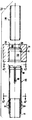
제1도는 본 발명이 적용되는 핵연료 집합체를 명료하게 하기 위하여 부분적으로 절단한 정면도.1 is a front view partially cut to clarify the fuel assembly to which the present invention is applied;
제2도는 본 발명을 실시하는 고착구조의 단면 분해 부품 배열도.2 is a cross-sectional disassembled parts arrangement diagram of the fixing structure of the present invention.
제3도는 고착구조가 조립된 상태로 단면 측면도.3 is a cross-sectional side view with the fixing structure assembled.
제4도는 제3도의 선 4-4을 따라 절취한 조립된 고착구조의 평면도.4 is a plan view of the assembled fastening structure cut along line 4-4 of FIG.
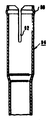
제5도는 제3도의 선 5-5을 따라 절취한 단면도.5 is a cross-sectional view taken along the line 5-5 of FIG.
제6도, 제7도 및 제8도는 쉐정관을 삽입 위치내에 고착시키기 위한 수단의 다른 변경 양태를 도시하는 제3도의 유사도.6, 7 and 8 show a similar view of FIG. 3 showing another alternative embodiment of the means for securing the sheath in the insertion position.
제9도는 본 발명의 교체 실시양태를 도시하는 제2도와 유사한 단면분해 부품 배열도.9 is a cross-sectional view of a component arrangement similar to that of FIG. 2 showing an alternative embodiment of the present invention.
제10도는 제9도에 도시한 고착구조의 내부 소켓트의 선 10-10을 절취한 평면도.FIG. 10 is a plan view taken along line 10-10 of the internal socket of the fixing structure shown in FIG. 9. FIG.
제11도는 변경된 내부 소켓트의 상단부 확대 단편도.11 is an enlarged fragmentary view of the top of the modified inner socket.
제12도는 제9도의 선 12-12를 절취한 단면도.12 is a cross-sectional view taken along the line 12-12 of FIG.
제13도는 제9도에 도시한 고착구조의 쇄정부재의 변경된 상단부의 확대 단편도.FIG. 13 is an enlarged fragmentary view of the modified upper end of the locking member of the fixing structure shown in FIG.
제14도는 조립된 상태에 있는 제9도의 고착구조의 단면도.14 is a sectional view of the fixing structure of FIG. 9 in an assembled state.
제15도는 제14도의 선 15-15를 절취한 평면도.FIG. 15 is a plan view taken along line 15-15 of FIG.
제16도는 본 발명을 실시하는 고착구조의 내부 소켓트의 변경양태를 도시하는 단면도.Fig. 16 is a sectional view showing a modification of the internal socket of the fixing structure for implementing the present invention.
* 도면의 주요부분에 대한 부호의 설명* Explanation of symbols for main parts of the drawings
10 : 연료 집합체 12 : 하부 노즐10
14 : 제어봉 가이드관 22 : 상부 노즐14: control rod guide tube 22: upper nozzle
40 : 내부소켓트 42 : 외부 소켓트40: internal socket 42: external socket
46 : 슬리이브 48 : 벌지46: Sleeve 48: Bulge
50 : 슬롯 60, 62 : 레지50:
64 : 몸체부 66 : 플렌지64 body portion 66 flange
본 발명은 일반적으로 원자로용 연료 집합체에 관계하며 상세하게는 제어용 가이드관의 상단부에 연료 집합체의 상부 노즐을 탈착가능하게 설치하기 위한 개량된 부착구조에 관한 것이다.The present invention generally relates to a fuel assembly for a nuclear reactor, and more particularly, to an improved attachment structure for detachably installing an upper nozzle of a fuel assembly at an upper end of a control guide tube.
대부분의 원자로에 있어서, 노심부는 다수의 신장된 연료 요소 즉 연료 집합체라 언급되는 골격 구조에 의해 지지되는 동시에 그 내부에 통합되어 있는 연료봉으로 이루어진다. 연료 집합체는 일반적으로 신장하여 지지대를 수용하며 상부 및 하부의 횡방향으로 신장하는 노심지지판과 정렬된다.In most reactors, the core consists of fuel rods that are supported by and integrated within a number of elongated fuel elements, ie, skeletal structures referred to as fuel assemblies. The fuel assembly generally extends to accommodate the support and is aligned with the transversely extending core support plates of the upper and lower sides.
가장 통상적인 배열에서, 노심지지통의 장축은 수직으로 신장하며 다수의 연료 집합체도 또한 수직으로 배열되어 하부지지판의 상부에 설치된다. 이와 같은 연료 집합체의 통상적인 설계는 제어봉 가이드관에 고착되는 동시에 연료 집합체를 따라 수직방향으로 일정간격으로 배열되는 횡방향의 그리드에 의해 규칙적인 배열로 유지되는 다수의 연료봉 및 제어봉 가이드관을 포함한다. 상부 및 하부노즐은 완전한 연료 집합체 구조를 형성하기 위하여 그의 양단부에서 제어봉 가이드관에 고착된다. 상부 및 하부노즐은 그 사이에서 봉을 고정시키면서 연료봉의 단부들로부터 각각 상부 및 하부로 약간씩 신장된다.In the most common arrangement, the long axis of the core support barrel extends vertically and a plurality of fuel assemblies are also arranged vertically and installed on top of the lower support plate. A typical design of such a fuel assembly includes a plurality of fuel rods and control rod guide tubes that are held in a regular arrangement by a transverse grid that is secured to the control rod guide tubes and arranged at regular intervals in the vertical direction along the fuel assembly. . The upper and lower nozzles are fixed to control rod guide tubes at their ends to form a complete fuel assembly structure. The upper and lower nozzles extend slightly up and down from the ends of the fuel rod, respectively, with the rod fixed therebetween.
원자로를 운전하는 동안, 연료 집합체의 연료봉은 때때로 일차적으로 내부 응력으로 야기되는 균열을 일으켜서 원자로의 일차냉각수내로 분열 생성물이 누출되도록 한다. 이와 같은 분열 생성물은 연료교체 작업을 하는 동안 방수 원자로 공동 내로 또는 사용연료 집합체가 저장되는 푸울을 통해 순환되는 냉각수내로 방출될 수도 있다. 연료봉은 상부 및 하부노즐에 용접된 가이드관이 있는 완전한 집합체의 일부이기 때문에, 손상봉을 탐지 및 제거하는 것이 곤란하다.During operation of the reactor, the fuel rods in the fuel assembly sometimes crack, primarily caused by internal stresses, causing cracked products to leak into the reactor's primary coolant. Such fission products may be discharged into the coolant circulated through the water reactor cavity or through the pool in which the spent fuel assembly is stored during the fuel replacement operation. Since the fuel rods are part of a complete assembly with guide tubes welded to the upper and lower nozzles, it is difficult to detect and remove damaged rods.
이와 같은 것을 달성하기 위하여, 일차적으로 원자로 심으로부터 손상 연료 집합체를 제가한 다음 노즐을 제어봉 가이드관에 고착시킨 용접을 파쇄시키는 것이 필요하다. 용접을 파쇄하는 데에 필요한 파괴적인 조치가 종종 가이드관 및 노즐에 재용접이 불가능한 정도로 손상을 일으켜서, 연료 집합체가 원자로내에서 재사용되는 것을 부적합하게 한다.To achieve this, it is necessary first to remove the damaged fuel assembly from the reactor shim and then to break the weld in which the nozzle is fixed to the control rod guide tube. The destructive measures needed to break the weld often damage the guide tubes and nozzles to a degree that is impossible to reweld, making the fuel assembly unusable for reuse in the reactor.
연료고체가 고가인 점에 비추어서 또한 그들의 작동 및 보수비용을 최소화하기 위하여, 국내 및 국외의 업주들은 재구성 가능한 연료 집합체에 흥미를 표명하고 있다. 원자로 산업은 탈착 가능한 상부 노즐이 있는 재구성 가능한 연료 집합체를 마련함으로써 이 요구에 부응하며, 상부 노즐의 대부분은 상부 노즐을 제어봉 가이드관에 고착시키기 위하여 관통 배열을 적용하고 있으며, 관통 배열은 골격 집합체내에 연료봉을 접근시키기 위하여 상부 노즐이 제거될 수 있게 한다.In view of the high cost of fuel solids and to minimize their operating and maintenance costs, domestic and foreign owners have expressed interest in reconfigurable fuel assemblies. The reactor industry responds to this requirement by providing a reconfigurable fuel assembly with a removable top nozzle, most of which employ a through arrangement to secure the top nozzle to the control rod guide tube, the through arrangement being within the skeletal assembly. Allows the top nozzle to be removed to access the fuel rods.
이와 같은 재구성 가능한 연료 집합체의 한 형태가 미합중국 특허 제3,770,583호 및 제3,814,667호에 명세되어 있으며 각각은 내부에 호울드-다운 장치를 갖는 상부 노즐을 도시하는 동시에 단부 평판을 관통하는 상부 정렬 포스트에 배치된 코일 스프링을 구비하며 이때 평판의 하부에는 고정 너트가 배치된다. 상부 호울드-다운 평판을 정렬위치상에 활동가능하게 설치되며, 코일 스프링이 호울드-다운 평판과 단부 평판사이에 압착에 의하여 개삽된다. 이와 같은 형태의 집합체를 개량하기 위한 노력으로서 미합중국 특허 제3,992,259호가 다른 관통 연결 배열을 명세하고 있으며, 제어봉 가이드관 상에 상부 노즐을 탈착 가능하게 고착시키기 위해 사용되는 또 다른 형태의 관통 배열이 미합중국 특허 제3,858,868호에 명세되어 있다.One form of such a reconfigurable fuel assembly is specified in US Pat. Nos. 3,770,583 and 3,814,667, each showing an upper nozzle with a holder-down device therein and placed in an upper alignment post through the end plate. And a fixed nut is disposed at the bottom of the plate. The upper holder-down plate is operatively installed on the alignment position, and the coil spring is inserted by compression between the holder-down plate and the end plate. In an effort to improve this type of assembly, US Pat. No. 3,992,259 specifies another through connection arrangement, and another form of through arrangement used to detachably secure an upper nozzle onto a control rod guide tube is a US patent. 3,858,868.
관통정렬을 적용하는 이와 같은 통상적인 재구성 가능한 연료 집합체를 높은 제작비용, 복잡한 설계 및, 상부 노즐의 제거와 재고착이 곤란한 점등의 결점을 겪을 뿐만 아니라 조사후에 관통 연결이 부식 및 작용 불가능하게 되는 문제를 제시한다는 것을 발견하였으며, 이리하여 이들 구성 부품에 상당한 손상을 야기하는 동시에 연료 집합체의 재사용이 부적합하게 할 수도 있는 어떤 파괴적인 조치가 노즐 및 가이드관에 취해져야 한다는 것을 요구하고 있다.Such conventional reconfigurable fuel assemblies applying through-alignment suffer from high manufacturing costs, complex design, and lighting defects that make it difficult to remove and refit the top nozzle, as well as corrosion and inability to penetrate the connection after irradiation. It has been found that the present invention requires that any destructive measures be taken on the nozzles and guide tubes, which can cause significant damage to these components and at the same time make the reuse of fuel assemblies unsuitable.
제어봉 가이드관과 같은 연료 집합체 구성 부품에 손상없이 용이하게 제거 및 재삽입될 수 있는 방법으로 연료 집합체의 상부 노즐을 탈착 가능하게 설치하기 위한 개량된 고착구조를 마련함으로써 이와 같은 문제점 및 결점을 경감시키는 것이 본 발명의 주요한 목적이다.It is possible to alleviate these problems and drawbacks by providing an improved fixation structure for removably installing the upper nozzle of the fuel assembly in such a way that it can be easily removed and reinserted without damage to fuel assembly components such as control rod guide tubes. It is the main object of the present invention.
따라서, 본 발명은 상부 노즐에 한정된 외부소켓트와 가이드관의 상단부에 한정된 내부소켓트를 구비하는 고착구조를 마련한다. 내부소켓트는 압축된 방면 위치와 팽창된 쇄정위치사이에서 이동가능하다. 압축된 방면 위치에서, 내부 소켓트는 제거되어서 외부소켓트내로 삽입될 수 있는 반면에, 내부소켓트의 확장된 쇄정위치 내부 및 외부소켓트는 함께 쇄정된다. 내부소켓트를 외부소켓트내의 쇄정위치에 유지하여 고착된 상부 노즐을 가이드관에 유지하기 위하여, 쇄정부재가 바람직하게는 신장된 관의 형태로 내부소켓트내로 삽입된다. 내부소켓트로부터 쇄정부재를 제거함으로써 내부소켓트가 방변위치로 이동될 수 있도록 하여 그로 인해 상부 노즐이 가이드 관으로부터 분리될 수 있도록 한다.Accordingly, the present invention provides a fixing structure having an outer socket defined in the upper nozzle and an inner socket defined in the upper end of the guide tube. The inner socket is movable between the compressed lateral position and the expanded locking position. In the compressed lateral position, the inner socket can be removed and inserted into the outer socket, while the extended locking position inner and outer sockets of the inner socket are locked together. In order to hold the inner nozzle in the locking position in the outer socket and retain the fixed upper nozzle in the guide tube, the locking member is preferably inserted into the inner socket in the form of an elongated tube. By removing the locking member from the inner socket, the inner socket can be moved to the deflected position, thereby allowing the upper nozzle to be separated from the guide tube.
본 발명의 양호한 실시양태에서, 외부소켓트는 상부 노즐의 하부 어뎁터 판에 환상의 홈으로 형성된 통로의 형태로 있다. 내부소켓트는 상단부에 형성된 외주 벌지를 갖는 슬리이브이다. 슬리이브의 하단부는 가이드관의 상단부에 연결된다. 슬리이브상의 벌지가 통로의 환상 홈내로 삽입되고 또 그로부터 제거될 수 있도록 하기 위하여, 슬리이브가 상단부에 적어도 하나의 신장된 슬롯을 가지며 벌지는 내부 탄성 와해가 압축된 방면 위치로 갈 수 있도록 벌지를 통해 신장한다.In a preferred embodiment of the invention, the outer socket is in the form of a passage formed in an annular groove in the lower adapter plate of the upper nozzle. The inner socket is a sleeve having an outer bulge formed in the upper end. The lower end of the sleeve is connected to the upper end of the guide tube. In order to allow the bulge on the sleeve to be inserted into and removed from the annular groove of the passageway, the sleeve has at least one elongated slot at the top and the bulge allows the internal elastic breakage to reach the compressed lateral position. Elongate through.
고착 구조는 또한 내부소켓트내의 삽입위치에 쇄정부재를 고착시키기 위한 수단을 구비한다. 본원에 명세된 일실시양태에서, 고착수단 쇄정부재의 상단부에 배치되어 있는 동시에 상부 노즐에 마련된 요부 또는 구멍내로 변형된 박벽의 환상 플랜지 형태를 취하고 있다. 도시된 또다른 일실시 양태에서, 고착 수단은 상부 노즐의 어뎁터핀 내에 외부 소켓트를 한정하는 통로의 상단부의 내경보다 약간 큰 외경을 갖도록 외부로 돌출한 쇄정부재의 상부 주변 모서리부를 갖는다. 이리하여, 쇄정부재가 통로내로 삽입되면 통로의 상부 환상벽부와 빽빽한 마찰 적합성이 형성된다. 고착수단은 쇄정부재가 통로내로 삽입된 후에 쇄정부재의 상부내로 형성된 몇 개의 벌지 즉 첨두를 가져서 벌지가 통로내에 한정된 어댑터판의 주변홈 내로 신장하도록 하고 있다.The securing structure also includes means for securing the locking member at an insertion position in the inner socket. In one embodiment described herein, it takes the form of an annular flange of thin wall disposed at the upper end of the fixation means locking member and deformed into the recess or hole provided in the upper nozzle. In another embodiment shown, the securing means has an upper peripheral edge of the locking member protruding outward to have an outer diameter slightly larger than the inner diameter of the upper end of the passage defining the outer socket in the adapter pin of the upper nozzle. Thus, when the locking member is inserted into the passage, a close friction fit with the upper annular wall portion of the passage is formed. The fastening means has several bulges, or peaks, formed into the top of the locking member after the locking member is inserted into the passage so that the bulge extends into the peripheral groove of the adapter plate defined in the passage.
이제 본 발명의 양호한 실시 양태가 첨부한 도면에 관하여 실시예에 의하여 설명될 것이다.Preferred embodiments of the present invention will now be described by way of example with reference to the accompanying drawings.
도면에서 동일 참조 숫자 몇몇 도면을 통하여 동일 또는 유사 부품을 표시한다. 또한, "전방", "후방", "좌측", "우측", "상방", "하방" 및 이와 유사한 용어는 본원에서는 편의상의 단어로서만 사용될 것이며 한정적인 용어로 해석되지는 않을 것이다.In the drawings, like reference numerals designate like or similar parts throughout the several views. Also, the terms “front”, “rear”, “left”, “right”, “upward”, “downward” and similar terms are used herein only as convenience words and shall not be construed as limiting terms.
이제 도면을 참조하면, 제1도에 도시된 연료 집합체(10)는 기본적으로 원자로(도시하지 않음)의 노심 영역내의 하부노심판(도시하지 않음)상에 집합체를 지지하기 위한 하단 구조 즉 하부노즐(12), 하부노즐(12)로부터 상방으로 돌출하는 다수의 종방향으로 싱장하는 제어봉 가이드관(14), 가이드관(14)를 따라 축방향으로 일정 배열을 이루고 있는 다수의 횡방향 그리드(16), 그리드(16)에 의하여 지지되는 동시에 횡방향으로 일정 간격을 이루고 조직화된 배열의 신장 연료봉(18), 집합체의 중앙에 위치한 기구 사용관(20) 및, 집합체 구성부품을 손상시킴이 없이 통상적으로 취급될 수 있는 완전한 집합체를 형성하기 위하여 하기에 완전히 명세된 방법으로 가이드관(14)의 상단부에 고착된 상단구조 즉 상부 노즐(22)로 이루어 진다.Referring now to the drawings, the
상부 노즐(22)는 밀폐부 또는 하우징을 한정하는 동시에 주변 모서리로부터 신장하는 직립 측벽(26)을 갖는 횡방향으로 신장하는 어뎁테판(24)과 그의 상부에서 측벽(26)으로부터 신장하는 환상의 방사상 플렌지(28)을 구비한다. 환상 플랜지(28)에 판상 스프링(30 : 제1도에는 하나만 도시)이 적절히 클램프되어 노심에서 유도되는 열팽창 또는 그와 유사한 것으로 인한 연료 집합체 길이의 변화를 허여하면서 상방향의 냉각수 흐름에 의해 야기되는 연료 집합체의 수압상승력을 방지하기 위하여 통상적인 방법으로 상부노심판(도시하지 않음)과 통합된다. 방사상으로 신장하는 플루우크(34 : fluke)를 갖는 통상의 봉 다발 제어 집합체(32)가 환상플랜지(28)에 의하여 한정된 개구부내에 배치되어 공지된 방법으로 제어봉 가이드관(14)내에서 제어봉을 수직으로 이동시키기 위하여 제어봉(36)의 상단부에 연결된다.The
연료 집합체(10)을 형성하기 위하여, 횡방향의 그리드(16)가 소정의 축방향으로 일정간격으로 배치된 위치에서 신장된 가이드관(14)에 고착되며, 연료봉(18)이 그리드(16)을 통해 삽입되며, 하부노즐(12)이 가이드관의 하단부에 적절히 고착된 다음 상부 노즐(22)이 본 발명을 실시하는 고착구조(38)에 의하여 가이드관(14)의 상단부에 고착된다.In order to form the
제2도 내지 제5도 특히 제2도와 제3도를 설명하면 가이드관(14)의 상단부에 상부 노즐(22)를 탈착가능하게 설치하기 위한 고착구조(38)의 양호한 실시양태가 설명될 것이다. 비록 각 가이드관(14)이 상부 노즐(22)에 고착되어 있지만, 하기의 설명은 일 가이드관의 고착만 설명할 것이며 나머지 가이드관은 동일한 방법으로 고착될 것이다. 기본적으로, 고착구조(38)은 가이드관(14)의 상단부상의 내부소켓트(40), 상부 노즐(22)에 형성된 외부소켓트 및, 외부소켓트(42)와 쇄정결합으로 내부소켓트(40)을 지지하는 쇄정부재(44)를 구비하여 상부 노즐(22)을 가이드관(14)에 탈착가능하게 고착시킨다. 이제 고착구조(38)을 만드는 이들 세 구성 부품의 각각인 외부소켓트(42), 내부소켓트(40) 및, 쇄정부재(44)가 상세히 논의될 것이다.2 to 5 and in particular FIG. 2 and FIG. 3, a preferred embodiment of the fixing
제2도에 양호하게 도시된 바와 같이, 내부소켓트(40)는 바람직하게도 공지된 방법으로 가이드관(14)의 상단부에 하단 벌지 적합성을 갖는 신장된 슬리이브(46)은 그의 상단부에 형성된 주변 벌지(48)을 가지며, 측면에 적어도 하나, 바람직하게는 세 개(제5도)의 신장된 종방향의 슬롯(50)을 갖는다. 벌지(48)은 설명이 진행됨에 따라서 쉽게 명백해지기 위하여 호형상을 하고 있다. 세 개의 종방향의 슬롯(50)은 슬리이브의 벽 주위를 외주방향으로 일정간격을 이루고 있으며 슬리이브의 상부 모서리로부터 축방향으로 하방으로 벌지(48)를 약간 지난만큼 신장한다. 슬롯(50)의 목적은 내부소켓트(40)가 외부소켓트(42)내로 삽입되고 제거될 수 있도록 하는 압축된 방면 위치로 슬리이브(46)의 상단부의 압축 즉 탄성 와해를 할 수 있도록 하는 것이다. 본원에서는 가이드관(14)에 고착된 것으로 도시되어 있지만, 슬리이브(46)은 그리드와 함께 적용된 슬리이브 종류의 변경 또는 통상적인 그리드 슬리이브로부터 분리된 슬리이브로서 가이드관의 상단부에 차례로 벌지 적합되는 상부 그리드(16)와 함께 상부 그리드(16)에 고착될 수 있다는 것을 주시해야만 한다. 또한, 벌지(48)와 같은 외주 벌지 및 슬롯(50)과 같은 신장 슬롯을 측면에 갖춤으로써 가이드관의 통합 상단부로서 내부소켓트(40)을 형성하는 것은 본 발명의 범주내에 있을 것이다.As best shown in FIG. 2, the
제2도를 다시 설명하면, 외부 소켓트(42)는 바람직하게는 상부노즐(22)의 어뎁터 평판(24)내에 한정된 축방향의 통로 형태이며 상부 구멍(52), 중간 구멍(54) 및 하부 구멍(56)으로 이루어지며, 하부 구멍은 그 벽에 하부 구멍(54)을 상부(56a : 홉(58)의 상부) 및 하부(56b : 홈(58)의 하부)로 나누는 환상의 홈(58)을 갖는다. 환상의 홈(58)은 슬리이브(46)상에 벌지(48)이 호형상에 부합되는 배열을 한다. 상부 구멍(52), 중간 구멍(54) 및 하부 구멍(56)은 모두 동축이며 상세히 말하면 서로 축방향으로 일렬로 정렬된다. 상부 구멍(52)는 중간 구멍(54)의 직경보다 큰 직경을 가지며, 중간 구멍(54)의 직경은 하부 구멍(56)의 직경보다 작다. 바람직하게도, 중간 구멍(54)의 직경은 슬리이브(46)의 내부직경과 같으며, 하부 구멍(56)의 직경은 슬리이브(46)의 외부직경과 같고, 환상홈(58)의 직경은 팽창된 쇄정위치에서의 벌지(48)의 외부직경과 같다. 소켓트벽은 상부 구멍(52)와 함께 중간 구멍(54)의 교차점에서 상부 레지(60 : ledge)를 한정하며 하부 구멍(56)과 함께 중간 구멍(54)의 교차점에서 하부 레지(62)를 한정 한다. 레지(62)는 슬리이브(46)의 방사상의 벽두께와 대체로 동일한 폭을 갖는다. 구멍과 외부소켓트(42)의 환상요부의 정렬, 크기 및 형상과 벌지(48 : 내부소켓트(40))와 함께 슬리이브(46)의 상단부의 크기 및 형상은 내부소켓트(40)가 외부소켓트(42 : 제3도)내의 팽창된 쇄정위치에 있을 때, 벌지(48)이 환상홈(58)가 파단, 슬리이브(46)의 상단부 즉 모서리가 하부레지(62)에 접속하며, 벌지(48)상부의 슬리이브의 단면이 하부 구멍(56)의 상부(56a)와 꼭 맞는 접촉을 하며, 벌지(48)하부의 슬리이브(46)의 단면이 하부 구멍(56)의 하부(56b)와 꼭 맞는 접촉을 하도록 되어 있다. 이와 같은 관계는 내부소켓트(40)와 외부소켓트(42)사이에 꼭 까는 즉 빈틈이 없는 간격을 산출하도록 하고 있다. 여기서 하부레지(62)의 일차적인 목적이 내부소켓트(40)가 외부소켓트(42)내로 삽입될 때 통로 내로의 슬리이브(46)의 적절한 축방향의 위치 설정을 위하여 정지부 즉 정렬 가이드로서 사용하고자 한다는데 있다는 것을 주지해야만 한다.Referring again to FIG. 2, the
다시, 제2도를 설명하면 고착구조(38)은 또한 외부소켓트(42)내의 팽창된 쇄정위치에 내부소켓트(40)을유지하기 위한 쇄정부재(44)를 구비한다. 바람직하게도, 쇄정부재(44)는 원통형 즉 관상의 몸체부(64)와 관의 상단부에 형성된 방사상의로 신장하는 쇼울더 즉 방사상의 플랜지(66)을 갖는 신장된 관이다. 몸체부(64)의 외부직경은 중간 구멍(54)의 직경보다 약간 작으며 마찬가지로 슬리이브(46)의 내부 직경보다 작아서 그 사이에 마찰 적합성을 설정하면서 빽빽한 활동가능 속박을 하고 있다. 확대된 쇼울더(66)의 외부직경은 상부 구멍(52)의 직경보다 약간작다. 제3도에 도시한 바와 같이 쇄정관의 삽입위치에서, 쇼울더(66)은 어뎁터 평판(24)의 상부 구멍(52)내에 배치되며, 관상 몸체부(64)중간 구멍(54)를 통해 신장하는 동시에 슬리이브(46)의 상단부내로 신장하는 동안 상부레지(60)상에 배치된다. 즉시 알 수 있는 바와 같이, 정렬은 쇄정부재(44)가 그의 삽입위치에서 환상홈(58)과의 팽창된 쇄정 속박으로 벌지를 유지하고 그의 압축된 방면 위치로 이동되는 것을 방지하며, 그로인해 외부소켓트(42)와의 쇄정 속박으로 내부소켓트(40)을 유지하며 가이드관(14)의 상단부에 상부 노즐(22)이 접속되게한다.Referring again to FIG. 2, the securing
또한 개량된 고착구조(38)은 진동력 및 그와 유사한 힘으로 인한 변위에 반하여 내부소켓트(40)내의 삽입 위치에 쇄정부재(44)를 고착하기 위한 수단을 구비한다. 제2도에 도시된 바와 같이, 양호한 실시양태에서 고착수단은 쇄정부재(44)를 방사상의 플랜지(66)으로부터 상방향으로 신장하는 축방향 박벽의 원형 플랜지(68) 형태를 취하고 있으며 축방향의 플랜지(68)은 변형이 가능하며, 그 부분이 상부 구멍(52 : 제3도 및 제4도)에 인접한 어텝터 평판(24)내에 형성된 요부 즉 구멍(70)내에 들어갈 수 있도록 되어 있다.The
간략하게 제2도 및 제3도를 설명하면, 상부 노즐(22)은 다음과 같은 방법으로 가이드관(14)에 고착되며 또한 그로부터 분리된다. 즉 그 상부에 벌지(48)을 구비한 슬리이브(46)의 상단부는 벌지(48)이 슬리이브(46)의 탄성적으로 압축된 단부가 팽창된 쇄정위치로 탄성적으로 복귀됨에 따라서 벌지(48)이 환상의 홈(58)내에 도달하며 맞물릴 때까지 압축되어 외부소켓트(42)의 하부 구멍(56)내로 삽입된다. 그런 다음, 쇄정부재(44)가 내부소켓트(40)의 상부내로 삽입가능하게 신장하며 홈(58)과 쇄정속박으로 벌지(48)을 유지하도록 내부소켓트(40)내로 삽입된다. 최종적으로, 쇄정부재(44)의 축방향의 플랜지(68)가 요부(70)내로 변형된다. 상부 노즐(22)을 고착시키는 교체적인 방법은 내부소켓트(40), 외부소켓트(42) 및 쇄정부재를 우선 소조립 부품으로서 상기에 기술된 방법으로 조립한 다음 슬라이브(46)의 하단부를 가이드관(14)의 상단부상에 벌지 적합시킨다. 상부 노즐(22)를 분리시키기 위하여, 쇄정부재(44)가 플랜지(68)과 요부(70)사이의 쇄정 속박을 파단시키기 위하여 회전되며, 쇄정부재(44)는 외부소켓트(42)로부터 취출되는 동시에 어뎁터 평판(24)이 상승되어 그로인해 외부소켓트(42),따라서 노즐(22)이 가이드관(14)로부터 분리될 수 있게 하는 동시에 벌지(48)이 홈(58)의 외부로 캐밍아우트 되도록 한다.2 and 3, the
제6도, 제7도 및 제8도는 내부소켓트(40)내의 적절한 위치에 쇄정부재(44)를 유지하기 위하여 적용된 고착수단을 제외하고는 제2도 및 제3도에 관해 이제 막 기술된 양호한 실시양태와 대체로 동일하다. 이리하여, 제6도에 도시된 교체 실시양태에서, 고착 수단이 어뎁터 평판(24)의 상부 구멍(62)내의 환상요부(74)에 배치된 분할 접속링(72)이다. 링(72)는 쇄정부재(44)가 쇄정위치의 외부로 수직 상방으로 이동되는 것을 방지하기 위하여 쇼울더 즉 방사상 플랜지(66)의 상부 표면을 속박한다. 제7도에서, 고착수단은 상부 구멍(52)의 벽에 마련된 내부 관통부(76)을 삽입적으로 속박하는 방사상 플랜지(66)의 외부측 표면상에서 외부 관통부(78)의 형태를 취하고 있다. 또한 제8도에서 도시된 교체 실시 양태에서, 고착 수단(80)은 쇄정부재(44)의 몸체부(64)와 슬리이브(40)의 사이에서 벌지-적합성의 형태를 취하고 있다.6, 7 and 8 have just been described with respect to FIGS. 2 and 3 except for fastening means adapted to hold the locking
이전 실시양태가 쇄정부재에 대한 고착 수단에 대해서만은 서로 다른 반면에, 제9도 내지 제15도에 도시된 실시양태는 고착구조가 다소 변경된 슬리이브 즉 내부소켓트(82), 외부소켓트(84) 및, 쇄정부재(86)를 적용한다는 다른 양상에도 또한 다르다.Whereas the previous embodiment differed only with respect to the fastening means to the locking member, the embodiment shown in FIGS. 9 to 15 shows a sleeve with a slightly changed fixing structure, namely an
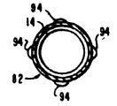
더 상세히 설명하면, 내부소켓트(82)는 상부 모서리(90)으로부터 단지 짧은 간격만으로 형성된 외부 벌지(90)을 가지며, 그의 상단부에 네 개의 신장된 슬롯(92 : 제10도)이 구비되며, 소켓트(82)에 관하여 원주 방향으로 대체로 등거리로 배치된 영역으로 네개의 벌지(94)에 의하여 세 개의 축 방향으로 일정간격을 이루는 영역에서 가이드관에 벌지 적합된 하단부를 갖는다. 제11도는 외주벌지(88) 상부의 상단부가 예로서 4-5도 정도로 약간 외부로 돌출된 다소 변경된 내부소켓트(82)를 도시한다.In more detail, the
외부소켓트(84)는 바람직하게는 상부 노즐(22)의 어뎁터 평판(24)내의 축방향 통로 형태로서 상부 구멍(98), 하부 구멍(100) 및 구멍(100)벽내의 환상홈(102)으로 이루어진다. 하부 구멍(100)은 상부 구멍(98)보다 길며 그 내부의 환상홈(102)은 상부 및 하부 구멍(98, 100)사이의 교차점에 형성된 레지 즉 쇼울더(104)의 하부에 짧은 간격으로 배치된다. 벌지(88)이 외부소켓트(84)내의 홈(102)와 계합되는 적절한 축방향 위치에 내부소켓트(82)를 정지시키기 위하여 하부 구멍(100)의 직경이 상부 구멍(98)보다 크며 이리하여 내부소켓트(82)가 외부소켓트(84)내로 삽입됨에 따라서 내부소켓트(82)의 상부 모서리(90)와 통합하는 정지부로서 사용되는 동시에 하방으로 향하는 레지(104)를 형성한다.The outer socket 84 is preferably in the form of an axial passage in the
이와 같은 실시양태에서 쇄정부재(86)에 대한 고착수단은 내부소켓트(82)상의 환상벌지(88)의 내부표면에 의하여 한정된 외부홈으로 벌지 적합되도록 쇄정부재(86)가 통로내로 삽입된 후에 쇄정부재(86)의 상부에 형성된 한쌍의 벌지(106 : 제15도)형태를 취하고 있다. 대신에 바람직하게도 벌지(106)에 덧붙여서 쇄정부재(86) 이 외부로 약간 즉, 쇄정부재(80)이 쇄정위치에 있을 때 상부 구멍(98)의 외주벽과 모서리부(108)사이에 견실한 마찰 적합성을 부여하기에 충분하게만(예로써 1내지 2도) 돌출된 상부 주변 모서리부(108 :제13)를 구비할 수도 있다.In such an embodiment, the locking means for the locking
마지막으로 제16도를 설명하면, 소켓트(96)가 별개 품목이 아니라 관(14)의 통합부 즉 상부 신장으로 형성되는 것을 제외하고는 제9도 내지 제14도에 도시된 내부소켓트(82)와 유사한 변경양태의 내부소켓트(96)를 도시한다. 본원에 명세된 다른 실시양태에서 적용된 내부소켓트가 유사한 방법으로 변경될 수 있다는 것을 감지할 것이다.Finally, with reference to FIG. 16, the internal sockets shown in FIGS. 9-14 are shown except that the socket 96 is formed as an integral part of the
Claims (21)
Applications Claiming Priority (2)
| Application Number | Priority Date | Filing Date | Title |
|---|---|---|---|
| US53777583A | 1983-09-30 | 1983-09-30 | |
| US537775 | 1983-09-30 |
Publications (2)
| Publication Number | Publication Date |
|---|---|
| KR850002347A KR850002347A (en) | 1985-05-10 |
| KR910006873B1 true KR910006873B1 (en) | 1991-09-09 |
Family
ID=24144048
Family Applications (1)
| Application Number | Title | Priority Date | Filing Date |
|---|---|---|---|
| KR1019840006025A KR910006873B1 (en) | 1983-09-30 | 1984-09-28 | Nuclear reactor fuel assembly with a removable top nozzle |
Country Status (9)
| Country | Link |
|---|---|
| EP (1) | EP0140588B1 (en) |
| JP (1) | JPS6093988A (en) |
| KR (1) | KR910006873B1 (en) |
| DE (1) | DE3470974D1 (en) |
| ES (1) | ES8702043A1 (en) |
| IL (1) | IL72907A (en) |
| IT (1) | IT1176827B (en) |
| PH (1) | PH21497A (en) |
| ZA (1) | ZA847032B (en) |
Families Citing this family (19)
| Publication number | Priority date | Publication date | Assignee | Title |
|---|---|---|---|---|
| FR2546113A2 (en) * | 1983-03-21 | 1984-11-23 | Mesnel Sa Ets | Sealing strip for guiding retractable vehicle window |
| FR2543074B1 (en) * | 1983-03-21 | 1987-05-07 | Mesnel Sa Ets | "FLUSHING" MOBILE WINDOWS, ESPECIALLY FOR AUTOMOBILE DOORS |
| SE440835B (en) * | 1984-11-02 | 1985-08-19 | Asea Atom Ab | PROCEDURE INCLUDING A REMOVAL OF A VERTICAL MIDDLE AXLE AND CIRCULATED SECTION CURRENTLY EXTENDED LEADERSHIP FROM A HORIZONTAL TOP PLATE IN A NUCLEAR FUEL CARTRIDGE |
| US4684498A (en) * | 1985-03-29 | 1987-08-04 | Westinghouse Electric Corp. | Guide thimble captured locking tube in a reconstitutable fuel assembly |
| US4699758A (en) * | 1985-04-02 | 1987-10-13 | Westinghouse Electric Corp. | Reusable locking tube in a reconstitutable fuel assembly |
| US4699759A (en) * | 1985-06-12 | 1987-10-13 | Westinghouse Electric Corp. | Double lock joint for attaching top nozzle to guide thimbles of nuclear fuel assembly |
| US4684500A (en) * | 1985-09-12 | 1987-08-04 | Westinghouse Electric Corp. | Guide thimble captured locking tube in a reconstitutable fuel assembly |
| US4688416A (en) * | 1985-11-12 | 1987-08-25 | Westinghouse Electric Corp. | Fixture and method for rectifying damaged guide thimble insert sleeves in a reconstitutable fuel assembly |
| ES2004864A6 (en) * | 1985-11-12 | 1989-02-16 | Westinghouse Electric Corp | Fixture for rectifying guide-thimble damage in reconstitutable nuclear fuel assemblies. |
| US4684499A (en) * | 1985-12-10 | 1987-08-04 | Westinghouse Electric Corp. | Burnable absorber rod releasable latching structure |
| FR2636767B1 (en) * | 1988-09-19 | 1990-12-14 | Framatome Sa | METHOD AND DEVICE FOR EXTRACTING A LOCKING SLEEVE FROM A REMOVABLE GUIDE TUBE FROM A FUEL ASSEMBLY OF A NUCLEAR REACTOR |
| FR2636768B1 (en) * | 1988-09-19 | 1990-12-14 | Framatome Sa | REMOVABLE FUEL ASSEMBLY FOR A NUCLEAR REACTOR COOLED BY LIGHT WATER |
| EP0360664B1 (en) * | 1988-09-19 | 1994-06-01 | Framatome | Removable fixture device for a guide tube of a fuel assembly end nozzle of a nuclear reactor |
| US4980121A (en) * | 1989-07-28 | 1990-12-25 | Westinghouse Electric Corp. | Protective device for lower end portion of a nuclear fuel rod cladding |
| US5149495A (en) * | 1990-05-24 | 1992-09-22 | General Electric Company | Water rod for nuclear reactor and method for providing and using same |
| US5479464A (en) * | 1994-08-30 | 1995-12-26 | Westinghouse Electric Corporation | Expandable top nozzle and device for securing same to a nuclear fuel assembly |
| FR2864324B1 (en) * | 2003-12-22 | 2008-07-18 | Framatome Anp | END CAP FOR FUEL NOSE ASSEMBLY FOR REFRIGERANT FLUID FLOW AND CORRESPONDING ASSEMBLY |
| JP7066121B2 (en) * | 2018-05-18 | 2022-05-13 | ペット エンジニアリング アンド サーヴィシーズ エスアールエル | Coupling structure for liquid fuel combustors and liquid fuel combustors |
| CN113118682B (en) * | 2019-12-30 | 2023-04-14 | 中核北方核燃料元件有限公司 | Split rod bundle clamp for automatic end plate welding |
Family Cites Families (5)
| Publication number | Priority date | Publication date | Assignee | Title |
|---|---|---|---|---|
| US4219386A (en) * | 1977-06-10 | 1980-08-26 | Exxon Nuclear Company, Inc. | PWR Integral tie plate and locking mechanism |
| FR2493024B1 (en) * | 1980-10-29 | 1986-08-29 | Franco Belge Combustibles | REMOVABLE CONNECTION DEVICE FOR PRODUCING COMBUSTIBLE ASSEMBLIES OF LIGHTWATER NUCLEAR REACTORS |
| FR2529704B1 (en) * | 1982-07-01 | 1987-09-04 | Commissariat Energie Atomique | DEVICE FOR FASTENING A GUIDE TUBE INTO THE END PIECE OF A NUCLEAR REACTOR FUEL ASSEMBLY |
| FR2533350B1 (en) * | 1982-09-16 | 1988-07-08 | Fragema Framatome & Cogema | NUCLEAR FUEL ASSEMBLY WITH REPLACEABLE PENCILS |
| DE3330357A1 (en) * | 1982-09-23 | 1984-03-29 | Westinghouse Electric Corp., 15222 Pittsburgh, Pa. | METHOD FOR REPAIRING A CORE REACTOR FUEL |
-
1984
- 1984-09-06 ZA ZA847032A patent/ZA847032B/en unknown
- 1984-09-10 IL IL72907A patent/IL72907A/en unknown
- 1984-09-20 PH PH31248A patent/PH21497A/en unknown
- 1984-09-27 ES ES536284A patent/ES8702043A1/en not_active Expired
- 1984-09-27 IT IT22866/84A patent/IT1176827B/en active
- 1984-09-27 JP JP59200715A patent/JPS6093988A/en active Granted
- 1984-09-28 EP EP84306629A patent/EP0140588B1/en not_active Expired
- 1984-09-28 DE DE8484306629T patent/DE3470974D1/en not_active Expired
- 1984-09-28 KR KR1019840006025A patent/KR910006873B1/en not_active IP Right Cessation
Also Published As
| Publication number | Publication date |
|---|---|
| KR850002347A (en) | 1985-05-10 |
| EP0140588A1 (en) | 1985-05-08 |
| PH21497A (en) | 1987-11-10 |
| ES536284A0 (en) | 1986-12-01 |
| JPH0211119B2 (en) | 1990-03-12 |
| EP0140588B1 (en) | 1988-05-04 |
| DE3470974D1 (en) | 1988-06-09 |
| ES8702043A1 (en) | 1986-12-01 |
| JPS6093988A (en) | 1985-05-25 |
| IT1176827B (en) | 1987-08-18 |
| ZA847032B (en) | 1985-08-28 |
| IT8422866A0 (en) | 1984-09-27 |
| IL72907A (en) | 1988-02-29 |
Similar Documents
| Publication | Publication Date | Title |
|---|---|---|
| KR910006873B1 (en) | Nuclear reactor fuel assembly with a removable top nozzle | |
| KR910004195B1 (en) | Device for fixing a guide ture in a recess on the end fitting of a nuclear reactor fuel assembly | |
| US4631168A (en) | Nuclear reactor fuel assembly with a removable top nozzle | |
| ES2326934T3 (en) | APPARATUS TO MAKE REPAIRS IN A PIPE UP OF A JUMP PUMP. | |
| KR910007920B1 (en) | Removable top nozzle and tool for a nuclear reactor fuel assembly | |
| JPS60104810A (en) | Apparatus and method for fixing two parts by retention screw | |
| EP0196916B1 (en) | Reusable locking tube in a reconstitutable fuel assembly | |
| KR100882195B1 (en) | Guide thimble of the dual tube type structure for nuclear fuel assembly | |
| JPS6352355B2 (en) | ||
| KR940003798B1 (en) | Double lock joint for attaching top nozzle to guide timbles of nuclear fuel assembly | |
| KR900000690B1 (en) | Reconstitutable fuel assembly for a nuclear reactor | |
| KR940010229B1 (en) | Guide thimble captured locking tube in a reconstitutable fuel assembly | |
| JP2843376B2 (en) | A device for removably securing a guide tube to the end fitting of a fuel assembly of a nuclear reactor | |
| KR940008251B1 (en) | Fixture for inserting locking tubes in reconstitutable nuclear fuel assembly | |
| KR100969934B1 (en) | Top nozzle assembly with improved release and coupling configuration in remote distance | |
| JPH0478956B2 (en) | ||
| KR970003771B1 (en) | Reconstitutable nuclear fuel assembly having locking tubes with dimples | |
| JPH083552B2 (en) | Fuel assembly upper nozzle | |
| JPH0478958B2 (en) | ||
| KR0163418B1 (en) | Demountable fuel assembly for a nuclear reactor cooled by light water | |
| JPH06201878A (en) | Spacer-pad for control rod | |
| US4568111A (en) | Detachable connection for a nuclear reactor fuel assembly | |
| US4895697A (en) | Top support lock | |
| US4620960A (en) | Method and apparatus for removably mounting a top nozzle on a nuclear reactor fuel assembly | |
| KR100709276B1 (en) | Index installation jig for extraction of rod from spent nuclear fuel assembly |
Legal Events
| Date | Code | Title | Description |
|---|---|---|---|
| A201 | Request for examination | ||
| G160 | Decision to publish patent application | ||
| E701 | Decision to grant or registration of patent right | ||
| GRNT | Written decision to grant | ||
| FPAY | Annual fee payment |
Payment date: 20040719 Year of fee payment: 14 |
|
| EXPY | Expiration of term |