KR910005731B1 - Fuel assembly for a nuclear reactor - Google Patents
Fuel assembly for a nuclear reactor Download PDFInfo
- Publication number
- KR910005731B1 KR910005731B1 KR1019840000862A KR840000862A KR910005731B1 KR 910005731 B1 KR910005731 B1 KR 910005731B1 KR 1019840000862 A KR1019840000862 A KR 1019840000862A KR 840000862 A KR840000862 A KR 840000862A KR 910005731 B1 KR910005731 B1 KR 910005731B1
- Authority
- KR
- South Korea
- Prior art keywords
- fuel
- plate
- fuel rod
- rod
- rods
- Prior art date
Links
Images


Classifications
-
- G—PHYSICS
- G21—NUCLEAR PHYSICS; NUCLEAR ENGINEERING
- G21C—NUCLEAR REACTORS
- G21C1/00—Reactor types
- G21C1/04—Thermal reactors ; Epithermal reactors
- G21C1/06—Heterogeneous reactors, i.e. in which fuel and moderator are separated
-
- G—PHYSICS
- G21—NUCLEAR PHYSICS; NUCLEAR ENGINEERING
- G21C—NUCLEAR REACTORS
- G21C3/00—Reactor fuel elements and their assemblies; Selection of substances for use as reactor fuel elements
- G21C3/30—Assemblies of a number of fuel elements in the form of a rigid unit
- G21C3/32—Bundles of parallel pin-, rod-, or tube-shaped fuel elements
- G21C3/33—Supporting or hanging of elements in the bundle; Means forming part of the bundle for inserting it into, or removing it from, the core; Means for coupling adjacent bundles
- G21C3/3305—Lower nozzle
-
- Y—GENERAL TAGGING OF NEW TECHNOLOGICAL DEVELOPMENTS; GENERAL TAGGING OF CROSS-SECTIONAL TECHNOLOGIES SPANNING OVER SEVERAL SECTIONS OF THE IPC; TECHNICAL SUBJECTS COVERED BY FORMER USPC CROSS-REFERENCE ART COLLECTIONS [XRACs] AND DIGESTS
- Y02—TECHNOLOGIES OR APPLICATIONS FOR MITIGATION OR ADAPTATION AGAINST CLIMATE CHANGE
- Y02E—REDUCTION OF GREENHOUSE GAS [GHG] EMISSIONS, RELATED TO ENERGY GENERATION, TRANSMISSION OR DISTRIBUTION
- Y02E30/00—Energy generation of nuclear origin
- Y02E30/30—Nuclear fission reactors
Abstract
Description
제1도는 본 발명에 따른 연료 집합체의 부분 측면도.1 is a partial side view of a fuel assembly according to the present invention;
제2도는 제1도의 C-C 선을 따라 취한 부분 단면도.2 is a partial cross sectional view taken along the line C-C in FIG.
제3도는 제2도의 A-A 선을 따라 취한 수직 단면도.3 is a vertical sectional view taken along the line A-A of FIG.
제4도는 제2도의 B-B 선을 따라 취한 부분 단면도.4 is a partial cross-sectional view taken along the line B-B in FIG.
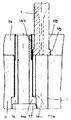
제5도는 제4도의 확대 상세도.5 is an enlarged detailed view of FIG.
* 도면의 주요부분에 대한 부호의 설명* Explanation of symbols for main parts of the drawings
1 : 연료봉 2 : 하부 플러그1: fuel rod 2: lower plug
3 : 상부 플러그 5 : 스페이서 그리드3: upper plug 5: spacer grid
6 : 하단부판 7 : 안내관6: bottom plate 7: guide tube
8 : 상단부판 12 : 하부 노심판8: upper plate 12: lower core plate
14 : 부착판 15 : 견부14: attachment plate 15: shoulder
16 : 중공부시16: hollow bush
본 발명은 연료봉이 연료 집합체의 하단부판에 유지되는 원자로용 연료 집합체에 관한 것이다.The present invention relates to a fuel assembly for a reactor in which a fuel rod is held on a bottom plate of the fuel assembly.
원자로용 연료 집합체, 특히 수형 원자로용 연료 집합체는 스페이서 그리드로 구성되는 구조부와 두 개의 단부판과, 스페이서 그리드와 단부판을 연결하는 안내관에 의해 유지되는 평행한 연료봉 다발로 구성된다.The reactor fuel assembly, in particular the fuel reactor for the male reactor, consists of a parallel fuel rod bundle held by a structure consisting of a spacer grid and two end plates, and a guide tube connecting the spacer grid and the end plate.
원통형의 길다란 연료봉은 이것을 다발 형태로 적소에서 유지시키는 스페이서 그리드에 결합된다.The cylindrical elongated fuel rod is coupled to a spacer grid that holds it in place in the form of a bundle.
일반적으로, 스페이서 그리드는 연료 집합체내의 일부 연료봉 대신 채택되는 안내관보다 짧은 길이를 갖는 연료봉의 횡방향 및 축방향 위치화를 제공한다. 따라서, 연료봉의 단부는 어떠한 곳에도 고정되지 않으며 단부판으로부터 일정한 거리에 위치한다.In general, the spacer grid provides for lateral and axial positioning of fuel rods having a shorter length than guide tubes employed instead of some fuel rods in the fuel assembly. Thus, the end of the fuel rod is not fixed anywhere and is located at a constant distance from the end plate.
스페이서 그리드에 의하여 봉의 축방향 및 횡방향 위치화를 제공하기 위하여, 봉에 횡방향의 큰 힘을 작용시키는 스프링을 사용하는 것이 필요하다.In order to provide axial and transverse positioning of the rod by means of a spacer grid, it is necessary to use a spring that exerts a large transverse force on the rod.
원자로심의 중성자 수량을 개선하기 위하여, 집합체의 그리드를 형성하도록 낮은 중성자 흡수율을 갖는 지르코늄 합금으로 제조된 것이 일반적으로 사용된다.In order to improve the neutron yield of the reactor core, one made of a zirconium alloy with a low neutron absorption is generally used to form a grid of aggregates.
그러나, 스프링은 방사선 조사 상태에서 스프링의 적절한 탄성적 및 역학적 특성을 가질 수 있도록 니켈합금으로 제조되어야 한다.However, the spring must be made of nickel alloy so that it can have the proper elastic and mechanical properties of the spring in the irradiation state.
그러므로, 연료봉의 한쪽 단부를 연료 집합체의 하단부판에 고정시키므로써, 연료봉의 횡방향 및 축방향 위치화 기능을 분리시키게 된다. 그러나, 이것은 하단부판의 구조를 복잡하게 하고, 분해를 어렵게 하며, 그리고 연료 집합체내의 일차 유체의 유동 단면적을 감소시키는 단점을 갖는다.Therefore, by fixing one end of the fuel rod to the bottom plate of the fuel assembly, the lateral and axial positioning functions of the fuel rod are separated. However, this has the disadvantage of complicating the structure of the bottom plate, making it difficult to disassemble, and reducing the flow cross-sectional area of the primary fluid in the fuel assembly.
그러므로, 본 발명의 목적은 길다란 원통형으로 서로 평행하게 배치되고, 봉에 대하여 횡방향인 스페이서 그리드로 구성되는 구조부와, 횡방향 단부판과, 스페이서 그리드와 단부판에 연결되고 일부 연료봉 다발대신 배치되는 안내관에 의하여 유지되는 연료봉 다발로 구성하는 원자로용 연료 집합체를 제공하는 것으로, 연료봉은 연료 집합체의 하부에 배치되는 단부판중 하나위에 하나의 봉 단부가 고정되며, 연료 집합체가 원자로심내에 수직 작동위치로 배치될 때, 이러한 연료 집합체는 용이한 해체와 적절한 일차 유체의 유동 단면적을 제공하는 한편, 봉의 효율적인 축방향 및 횡방향 위치화를 제공하는 간단한 구조의 하단부판을 구비하여야 한다.It is therefore an object of the invention to be arranged in parallel to each other in an elongated cylindrical form, consisting of a structure consisting of a spacer grid transverse to the rod, a transverse end plate, connected to the spacer grid and the end plate and arranged instead of some fuel rod bundles. A fuel assembly for a nuclear reactor comprising a fuel rod bundle held by a guide tube, wherein the fuel rod is fixed at one rod end on one of the end plates disposed below the fuel assembly, and the fuel assembly is operated vertically within the reactor core. When placed in position, such fuel assemblies should have a simple bottom plate that provides easy disassembly and flow cross-sectional area of the appropriate primary fluid, while providing efficient axial and transverse positioning of the rods.
상기 목적을 위하여, 연료 집합체는 각각의 연료봉에 대응하는 직경과 위치를 가지며 봉의 열에 각각 대응하는 평행한 홈으로 개방되어 있는 개구를 가지는 부착판에 의해 하단부판에 고정되고, 상기 홈은 단부판과 접촉상태에 있는 부착판의 하부표면에 형성되며, 각각의 연료봉은 횡단면이 120°각도로 적어도 세 방사방향 브랜치를 갖는 하부 플러그(2)를 구비하며, 대응하는 방사방향 연장부의 각각은 연료봉의 원통형 부분의 외형으로부터 방사방향으로 돌출하는 견부로서 하향으로 종단되고, 연료봉은 부착판을 횡단하여 높이가 홈의 깊이와 거의 동일한 돌출 하부 견부가 회전에 대항하여 유지되고 하단부판과 부착판 사이에 축방향으로 유지되도록 하기 위하여 대응 홈내에 배치된다.For this purpose, the fuel assembly is fixed to the bottom plate by an attachment plate having an opening and opening with parallel grooves corresponding to the rows of rods, respectively, with the diameter and position corresponding to each fuel rod, the groove being end plate and Formed on the lower surface of the attachment plate in contact, each fuel rod having a
본 발명이 더욱 명확하게 이해되도록 개선된 중성수량의 원자로에 사용된 본 발명에 따른 연료 집합체를 첨부도면을 참조하여 기술한다.DESCRIPTION OF THE PREFERRED EMBODIMENTS The fuel assembly according to the invention used in an improved neutral quantity reactor for the purpose of understanding the invention more clearly is described with reference to the accompanying drawings.
제1도에는 본 출원인의 프랑스공화국 특허출원 제 82/18,012호에 기술된 바와 같은 개선된 중성자 수량의 원자로에 사용된 연료 집합체가 도시되어 있다.1 shows a fuel assembly used in an improved neutron quantity reactor as described in Applicant's French Patent Application No. 82 / 18,012.
이러한 연료 집합체는 연료 펠릿을 에워싸는 외장 튜브로 구성되는 한셋트의 연료봉(1)을 포함한다. 외장튜브는 하단부에서 플러그(2)에 의하여 폐쇄되며 상단부에서 플러그(3)에 의하여 폐쇄된다. 하부 플러그(2) 바로 위에 위치하는 봉 영역(1a)은 봉의 중간 영역을 채우는 핵분열성 연료 물질대신 핵친화성 물질로 채워진다. 또한, 봉의 상부 플러그(3)바로 아래에 위치하는 봉 영역(1b)에도 핵친화성 물질이 채워진다. 따라서, 각각의 연료 집합체와 전체 원자로심에 핵친화성 물질의 상부 블랭킷과 하부 블랭킷이 형성되어, 상기 특허출원 제82/18,012호에서 기술된 바와 같이 원자로의 중성자 수량을 개선시킨다.This fuel assembly comprises a set of
연료봉(1)은 봉의 축방향 위치화를 위한 스페이서 그리드(5)와, 하단부판(6)과, 상단부판(8), 그리고 그리드(5)에 연결되고 한 단부가 하단부판(6)에 고정되고 다른 단부가 상단부판(8)에 고정되는 안내관(7)으로 구성하는 구조부에서 유지된다. 따라서 상기 안내관(7)은 봉의 지지구조부의 위치화 및 견고성을 제공한다. 안내관(7)은 하단부판용 부시(9) 또는 상단부판용 부시(10)의 나사부에 결합되는 탭 단부에 의하여 단부판(6,8)을 관통하는 개구내에 고정된다.The
상기 부시(9,10)를 안내관의 탭 단부내로 나사 결합시키면, 부시는 회전 억제된다. 연료 집합체는 제1도에 개략적으로 도시된 중앙 제어기(13)를 구비하는 장치에 의하여 하부 노심판(12)상에 그 하부를 고정시킨다. 연료 집합체 하부를 고정시키는 이러한 장치는 프라마토메 소시에떼 명의로 출원된 프랑스공화국 특허 출원 제 81/22,754호에 기술되어 있다.When the
제1, 제2, 제3, 제4 및 제5도를 참조하여 연료봉의 하부를 하단부판(6)상에 고정시키는 장치에 대하여 설명한다.An apparatus for fixing the lower part of the fuel rod on the
연료봉의 하부 플러그(2)는 제2도에 도시되어 있으며 서로 120°각도로 방사방향의 세 개의 브랜치(2a, 2b, 2c)를 구비하는 단면으로 길이의 대부분에 걸쳐 기계 가공된다. 상기 브랜치(2a, 2b, 2c)에 대응하는 각각의 방사 연장부는 하부에 방사방향을 돌출한 부분을 제외한 플러그 부분을 내접하는 원통형 부분내의 봉의 원형 단면에 대하여 돌출한 견부(15)를 포함한다.The
부착판(14)의 하부표면은 하단부판(6)을 관통하는 개구(17)내에 결합된 나사식 중공부시(16)에 의하여 상기판(14)이 고정되는 단부판(6)의 상부 표면상에 놓여진다. 각각의 개구부(17)는 부시(16)의 헤드(16a)를 지지하는 견부(17a)를 갖는다. 부시(16)의 나사부(16b)는 단부판(6)의 개구(17)의 연장부내에서 판(14)에서 제공된 탭 구멍에 나사결합된다. 부시(16)가 죄여진후, 개구(17)의 입구에 제공된 구멍내로 부시의 헤드(16a)가 연장되는 상부 스커트(16c)의 변형에 의하여 회전 억제된다. 이러한 방식으로 완전한 고정형태로 판(14)을 단부판(6)상에 고정시키는 것이 가능하다.The lower surface of the
부착판(14)은 연료봉(1)의 원통형의 직경과 동일한 직경을 가지며 연료봉 다발의 위치에 대응하는 위치에 있는 개구(18)를 포함한다. 봉과 개구(18) 각각의 연장부에 있어서, 단부판(6)도 봉의 직경과 동일한 직경의 구멍(20)이 뚫려있다. 그러므로, 단부판(6)은 이를 수직으로 관통하여 세 형태의 구멍, 즉 안내관의 고정개구, 판(14)이 나사식 중공부시(16)를 위한 통로 개구 그리고 봉(1)의 하부 주위에 원자로의 냉각수 통로를 제공하는 구멍(20)을 포함한다. 상기 중공 부시(16)도 냉각수 통로를 제공한다.The
이와 유사하게 부착판(14)은 이를 수직으로 관통하는 세 형태의 구멍, 즉, 안내관(7)이 통과하는 개구, 연료봉(1)을 고정시키는 개구(18) 그리고 부식(16)의 나사 결합을 위한 탭 구멍을 포함한다. 또한, 부착판(14)의 하부 표면은 서로 평행한 한셋트의 홈(21)를 포함하며, 그 각각은 연료봉의 열에 대응한다. 봉 하부의 통로를 위한 개구(18)는 그 하단부에서 홈(21)내부로 유입한다.Similarly, the
제1도에 도시된 바와 같이, 홈(21)의 깊이는 연료봉(1)의 플러그(2)상에 형성된 방사방향의 견부(15)의 높이와 일치한다. 상술된 바와 같이 개선된 중성자 수량을 갖는 원자로용 연료 집합체의 경우에 있어서, 상기 홈(21)의 깊이는 5mm이다. 방사방향으로의 견부(15)의 크기는 2mm이다.As shown in FIG. 1, the depth of the
판(14)의 하부 표면에 가공된 홈(21)의 폭은, 제2도에 도시된 바와 같이 봉 하부의 방사방향의 브랜치중 어느 하나가 홈의 축에 수직이 되도록 선택된다. 상기 세 브랜치는 120°각도로 배치되고, 봉의 축은 홈의 중간면보다 약간 넓게 오프세트되어, 봉을 판(14)상에 배치시키기 위하여 홈의 벽에 원통형 리세스(24)를 구비할 필요가 있다. 직경이 9.5mm인 봉을 갖는 연료 집합체의 경우에 있어서는, 홈의 폭은 8mm이다.The width of the
이하, 연료 집합체에 연료봉의 설치 및 고정시키기 위하여 필요한 작동을 기술한다.Hereinafter, the operation necessary for installing and fixing the fuel rod to the fuel assembly will be described.
우선, 부착판(14)은 안내관의 하단부상의 적소에서 위치하게 되며, 안내관의 위치에 대응하는 구멍 시스템을 포함한다. 그래서, 봉은 부착판(14)과 스페이서 그리드(5)를 통하여 삽입되고, 부착판(14)내에 형성된 홈(21)의 밑면상에 접촉하는 하부 플러그(2)의 결부(15)에 의하여 정지된다. 상기 봉은 회전을 방지시키는 홈내에 단한번의 방법으로 적소에 위치할 수 있다. 그리고 나서, 하부판(6)은 안내관의 단부상의 적소에 위치하게되며, 부착판(14)은 당부판(6)의 상부 표면상에 놓여지게 된다. 그후, 하단부판은 안내관 단부내로 나사결합될 때 회전방지시키는 나사형성된 부시(9)에 의하여 안내관에 부착된다.First, the
다음에, 부착판(14)은 단부판(6)에 형성된 홈 내측에 변형된 스커트(16c)에 의하여 그것이 나사결합될 때 회전방지시키는 나사식 부시(16)에 의하여 단부판(6)상에 고정된다. 그후, 연료봉(1)은 연료 집합체내에서 회전운동과 마찬가지로 축방향 병진운동도 완전히 방지된다. 연료봉은 봉을 고정시키는 작은 돌출부만을 포함하지만 종래 기술의 집합체의 스페이서 그리드에서 사용된 바와 같은 인코넬 스프링을 포함하지 않는 스페이서 그리드(5)에 의하여 측방향으로 고정된다.The
본 출원인의 실험은 작동중에 이러한 방식으로 고정된 연료봉이 원자로내에 비정상 모드의 진동 영향을 받지 않는 것이 입증되었다. 또한, 연료봉은 부착판(14)에 의하여 축방향으로 완전히 고정된다. 그럼에도 불구하고, 연료 집합체의 냉각수 유동 단면적은 연료봉의 단면적과 비슷한 단면적으로 단부판과 부착판을 통해 냉각수의 유동을 허용하는 하부 플러그의 형상과 중공 부시(6)에 의하여 상당히 잔존한다. 마지막으로, 판(14)으로부터 중공 부시(16)를 그리고 안내관(7)으로부터 부시(9)를 돌려 빼는 것이 충분하므로, 하단부판과 연료봉의 해체가 매우 용이하다. 해체시키는 동안, 부시 스커트는 부시의 회전방지를 해제하기 위하여 변형된다.Applicants' experiments have demonstrated that fuel rods fixed in this manner during operation are not subjected to abnormal modes of vibration in the reactor. In addition, the fuel rod is completely fixed in the axial direction by the
본 발명은 상술된 실시예에 국한되지 않으며, 모든 수정을 포함한다. 따라서, 상기 고정 수단이 상술된 부시와 같이 용이한 해체를 허용하면, 단부판(6)상에 부착판(14)을 고정시키는 다른 수단을 이용하는 것이 가능하다. 또한, 이러한 형상이 홈내에서 연료봉의 배향 및 회전방지를 허용하면, 상술된 것과 약간 상이한 연료봉의 하부 플러그의 측면 형상을 이용할 수 있다.The invention is not limited to the embodiments described above, but includes all modifications. Thus, if the fixing means allows easy disassembly as in the bush described above, it is possible to use other means for fixing the
결론적으로는, 본 발명에 따른 연료 집합체는 노심이 하부의 상부에 핵친화성 물질층을 포함하는 개선된 중성자 수량을 갖는 원자로에 적용될 뿐만아니라 연료 집합체의 중성자 흡수 물질량을 감소시켜 중성자 수지를 개선시키는 것을 목적으로 하는 모든 원자로의 경우에도 적용된다.In conclusion, the fuel assembly according to the present invention is not only applied to a reactor having an improved neutron yield including a layer of nuclear affinity material on top of the bottom, but also to improve the neutron resin by reducing the amount of neutron absorbing material in the fuel assembly. The same applies to all target reactors.
Claims (4)
Applications Claiming Priority (2)
| Application Number | Priority Date | Filing Date | Title |
|---|---|---|---|
| FR838303154A FR2541809B1 (en) | 1983-02-25 | 1983-02-25 | FUEL ASSEMBLY FOR A NUCLEAR REACTOR |
| FR3154 | 1983-02-25 |
Publications (2)
| Publication Number | Publication Date |
|---|---|
| KR840007791A KR840007791A (en) | 1984-12-10 |
| KR910005731B1 true KR910005731B1 (en) | 1991-08-02 |
Family
ID=9286291
Family Applications (1)
| Application Number | Title | Priority Date | Filing Date |
|---|---|---|---|
| KR1019840000862A KR910005731B1 (en) | 1983-02-25 | 1984-02-22 | Fuel assembly for a nuclear reactor |
Country Status (16)
| Country | Link |
|---|---|
| US (1) | US4657733A (en) |
| EP (1) | EP0118355B1 (en) |
| JP (1) | JPS59163589A (en) |
| KR (1) | KR910005731B1 (en) |
| AT (1) | ATE30979T1 (en) |
| BR (1) | BR8400773A (en) |
| CA (1) | CA1206631A (en) |
| DE (1) | DE3467651D1 (en) |
| DK (1) | DK163847C (en) |
| ES (1) | ES296341Y (en) |
| FI (1) | FI82782C (en) |
| FR (1) | FR2541809B1 (en) |
| GR (1) | GR81414B (en) |
| TR (1) | TR22133A (en) |
| YU (1) | YU35184A (en) |
| ZA (1) | ZA841135B (en) |
Families Citing this family (7)
| Publication number | Priority date | Publication date | Assignee | Title |
|---|---|---|---|---|
| FR2577342B1 (en) * | 1985-02-12 | 1989-06-16 | Commissariat Energie Atomique | FUEL ELEMENT FOR A NUCLEAR REACTOR |
| US4652425A (en) * | 1985-08-08 | 1987-03-24 | Westinghouse Electric Corp. | Bottom grid mounted debris trap for a fuel assembly |
| US4863681A (en) * | 1988-02-25 | 1989-09-05 | Combustion Engineering, Inc. | Replacement rod |
| SE510817C2 (en) * | 1992-04-28 | 1999-06-28 | Asea Atom Ab | Method of extending the life of a fuel cartridge in a nuclear reactor by turning up and down in this contained fuel rod after a certain operating time |
| RU2623580C1 (en) * | 2016-05-04 | 2017-06-28 | Публичное акционерное общество "Машиностроительный завод" | Nuclear reactor fuel assembly |
| RU182070U1 (en) * | 2018-05-15 | 2018-08-02 | Федеральное государственное бюджетное учреждение "Национальный исследовательский центр "Курчатовский институт" | FUEL ASSEMBLY OF A NUCLEAR WATER-WATER ENERGY REACTOR |
| EP3667676B1 (en) * | 2018-12-14 | 2021-01-20 | Framatome | Method and assembling system for inserting at least one nuclear fuel rod into spacer grids of a nuclear fuel assembly |
Family Cites Families (15)
| Publication number | Priority date | Publication date | Assignee | Title |
|---|---|---|---|---|
| US2884038A (en) * | 1955-01-19 | 1959-04-28 | Clarence W Payne | Bolt head having undercut portion to receive flowable lead washer |
| BE558245A (en) * | 1956-06-15 | |||
| US3738912A (en) * | 1969-09-10 | 1973-06-12 | Nukem Gmbh | Fuel element for high temperature reactor |
| US3960655A (en) * | 1974-07-09 | 1976-06-01 | The United States Of America As Represented By The United States Energy Research And Development Administration | Nuclear reactor for breeding U233 |
| FR2368785A1 (en) * | 1976-10-20 | 1978-05-19 | Framatome Sa | EASY DISASSEMBLY FUEL ASSEMBLY FOR NUCLEAR REACTOR |
| GB1582192A (en) * | 1977-06-03 | 1980-12-31 | Nuclear Power Co Ltd | Fuel sub-assemblies for nuclear reactors |
| DE2742692A1 (en) * | 1977-09-22 | 1979-04-05 | Siemens Ag | Pressurised water reactor fuel element - with control rod tubes firmly clamped at top into two=part head piece |
| FR2465916A1 (en) * | 1979-09-19 | 1981-03-27 | Framatome Sa | SECURITY SCREW ASSEMBLY |
| AU540259B2 (en) * | 1980-09-12 | 1984-11-08 | Westinghouse Electric Corporation | Reconstitutable fuel assembly |
| FR2491668B1 (en) * | 1980-10-08 | 1985-10-11 | Framatome Sa | NUCLEAR REACTOR FUEL ASSEMBLY |
| US4418036A (en) * | 1980-12-16 | 1983-11-29 | Westinghouse Electric Corp. | Fuel assembly for a nuclear reactor |
| US4452755A (en) * | 1982-01-29 | 1984-06-05 | The United States Of America As Represented By The United States Department Of Energy | Fuel rod retention device for a nuclear reactor |
| US4492668A (en) * | 1982-04-08 | 1985-01-08 | Westinghouse Electric Corp. | Apparatus and method for preventing the rotation of rods used in nuclear _fuel assemblies |
| DE3240061A1 (en) * | 1982-10-28 | 1984-05-03 | Kraftwerk Union AG, 4330 Mülheim | CORE REACTOR FUEL ELEMENT |
| DE3309884A1 (en) * | 1983-03-17 | 1984-09-27 | Thanh-Son Dipl.-Ing. 1000 Berlin Le | Reusable positively-locking lock for a screw/nut of a detachable screw connection |
-
1983
- 1983-02-25 FR FR838303154A patent/FR2541809B1/en not_active Expired
-
1984
- 1984-02-06 GR GR73723A patent/GR81414B/el unknown
- 1984-02-08 CA CA000447049A patent/CA1206631A/en not_active Expired
- 1984-02-14 US US06/579,940 patent/US4657733A/en not_active Expired - Fee Related
- 1984-02-16 ZA ZA841135A patent/ZA841135B/en unknown
- 1984-02-21 BR BR8400773A patent/BR8400773A/en unknown
- 1984-02-22 FI FI840729A patent/FI82782C/en not_active IP Right Cessation
- 1984-02-22 KR KR1019840000862A patent/KR910005731B1/en not_active IP Right Cessation
- 1984-02-24 DE DE8484400371T patent/DE3467651D1/en not_active Expired
- 1984-02-24 DK DK102884A patent/DK163847C/en not_active IP Right Cessation
- 1984-02-24 AT AT84400371T patent/ATE30979T1/en active
- 1984-02-24 TR TR22133A patent/TR22133A/en unknown
- 1984-02-24 EP EP84400371A patent/EP0118355B1/en not_active Expired
- 1984-02-24 YU YU00351/84A patent/YU35184A/en unknown
- 1984-02-24 JP JP59034118A patent/JPS59163589A/en active Granted
- 1984-02-24 ES ES1984296341U patent/ES296341Y/en not_active Expired
Also Published As
| Publication number | Publication date |
|---|---|
| DK163847C (en) | 1992-08-31 |
| FI82782C (en) | 1991-04-10 |
| FI82782B (en) | 1990-12-31 |
| FI840729A (en) | 1984-08-26 |
| JPS59163589A (en) | 1984-09-14 |
| EP0118355A1 (en) | 1984-09-12 |
| ZA841135B (en) | 1984-09-26 |
| JPH0317318B2 (en) | 1991-03-07 |
| DE3467651D1 (en) | 1987-12-23 |
| ES296341Y (en) | 1988-02-16 |
| DK163847B (en) | 1992-04-06 |
| CA1206631A (en) | 1986-06-24 |
| EP0118355B1 (en) | 1987-11-19 |
| TR22133A (en) | 1986-05-20 |
| FR2541809A1 (en) | 1984-08-31 |
| DK102884D0 (en) | 1984-02-24 |
| US4657733A (en) | 1987-04-14 |
| GR81414B (en) | 1984-12-11 |
| FR2541809B1 (en) | 1985-07-26 |
| ATE30979T1 (en) | 1987-12-15 |
| FI840729A0 (en) | 1984-02-22 |
| ES296341U (en) | 1987-08-01 |
| KR840007791A (en) | 1984-12-10 |
| DK102884A (en) | 1984-08-26 |
| BR8400773A (en) | 1984-10-02 |
| YU35184A (en) | 1990-12-31 |
Similar Documents
| Publication | Publication Date | Title |
|---|---|---|
| US4990304A (en) | Instrumentation tube features for reduction of coolant flow-induced vibration of flux thimble tube | |
| US4278501A (en) | Spring element for holding down nuclear reactor fuel assembly | |
| JPS62177487A (en) | Nuclear fuel aggregate with coolant guide tube having large diameter | |
| KR910005731B1 (en) | Fuel assembly for a nuclear reactor | |
| JPS6357756B2 (en) | ||
| US4778647A (en) | Vibration-damping extender for a thimble guide | |
| JP5421638B2 (en) | Radioisotope manufacturing structure | |
| US6310931B1 (en) | Device and method for locking rods in a bottom tie plate of a fuel assembly | |
| EP0386501B1 (en) | Improved hold-down spring clamps on fuel assembly top nozzle | |
| JPH0573194B2 (en) | ||
| KR950013234B1 (en) | Control cluster provided with removable control elements for nuclear fuel reactor | |
| EP0458202B1 (en) | Fuel assembly for a nuclear reactor | |
| US8958520B2 (en) | Top nozzle for nuclear fuel assembly having spring insert hole improved in fastening stability and method of manufacturing the same | |
| JPH0795112B2 (en) | Integrated locking device for upper nozzle | |
| JPH0566993B2 (en) | ||
| US4094558A (en) | Locking nut assembly with deformable locking sleeve | |
| JPH0558515B2 (en) | ||
| EP0467093A1 (en) | Guide tube insert assembly for use in a nuclear reactor | |
| US4560531A (en) | Device for partitioning off the core of a nuclear reactor | |
| US4752438A (en) | Cluster guide with centering and antivibratory positioning device for nuclear reactors | |
| GB2265686A (en) | A vibration dampener for dampening the vibration of a tubular member | |
| US5255300A (en) | Fuel assembly for boiling water reactors | |
| JP3108189B2 (en) | Top nozzle of nuclear fuel assembly | |
| US6285729B1 (en) | Fuel spacer/water rod capture apparatus and methods for boiling water nuclear reactors | |
| JPS5932888A (en) | Spacer holding means and under tieplate fixing tool for nuclear fuel assembly |
Legal Events
| Date | Code | Title | Description |
|---|---|---|---|
| A201 | Request for examination | ||
| E902 | Notification of reason for refusal | ||
| G160 | Decision to publish patent application | ||
| E701 | Decision to grant or registration of patent right | ||
| GRNT | Written decision to grant | ||
| FPAY | Annual fee payment |
Payment date: 19950728 Year of fee payment: 5 |
|
| LAPS | Lapse due to unpaid annual fee |