KR910005646B1 - Supporting housing for magnetic disk - Google Patents
Supporting housing for magnetic disk Download PDFInfo
- Publication number
- KR910005646B1 KR910005646B1 KR1019880000103A KR880000103A KR910005646B1 KR 910005646 B1 KR910005646 B1 KR 910005646B1 KR 1019880000103 A KR1019880000103 A KR 1019880000103A KR 880000103 A KR880000103 A KR 880000103A KR 910005646 B1 KR910005646 B1 KR 910005646B1
- Authority
- KR
- South Korea
- Prior art keywords
- spindle
- housing
- support
- magnetic
- outer plate
- Prior art date
Links
- 238000000034 method Methods 0.000 claims description 11
- 230000008569 process Effects 0.000 claims description 4
- 238000005520 cutting process Methods 0.000 description 8
- 230000007246 mechanism Effects 0.000 description 8
- 230000008901 benefit Effects 0.000 description 7
- 238000010586 diagram Methods 0.000 description 4
- 125000006850 spacer group Chemical group 0.000 description 4
- 101000606504 Drosophila melanogaster Tyrosine-protein kinase-like otk Proteins 0.000 description 3
- 238000005304 joining Methods 0.000 description 3
- 238000007789 sealing Methods 0.000 description 3
- 238000004519 manufacturing process Methods 0.000 description 2
- 238000003825 pressing Methods 0.000 description 2
- 230000035945 sensitivity Effects 0.000 description 2
- 238000000926 separation method Methods 0.000 description 2
- 206010044565 Tremor Diseases 0.000 description 1
- 230000001154 acute effect Effects 0.000 description 1
- XAGFODPZIPBFFR-UHFFFAOYSA-N aluminium Chemical compound [Al] XAGFODPZIPBFFR-UHFFFAOYSA-N 0.000 description 1
- 229910052782 aluminium Inorganic materials 0.000 description 1
- 230000008878 coupling Effects 0.000 description 1
- 238000010168 coupling process Methods 0.000 description 1
- 238000005859 coupling reaction Methods 0.000 description 1
- 239000000428 dust Substances 0.000 description 1
- 230000000694 effects Effects 0.000 description 1
- 239000011554 ferrofluid Substances 0.000 description 1
- 239000012530 fluid Substances 0.000 description 1
- 230000006870 function Effects 0.000 description 1
- 239000011796 hollow space material Substances 0.000 description 1
- 238000009434 installation Methods 0.000 description 1
- 238000012856 packing Methods 0.000 description 1
- 238000005192 partition Methods 0.000 description 1
- 230000009467 reduction Effects 0.000 description 1
- 238000003860 storage Methods 0.000 description 1
Images


Classifications
-
- G—PHYSICS
- G11—INFORMATION STORAGE
- G11B—INFORMATION STORAGE BASED ON RELATIVE MOVEMENT BETWEEN RECORD CARRIER AND TRANSDUCER
- G11B25/00—Apparatus characterised by the shape of record carrier employed but not specific to the method of recording or reproducing, e.g. dictating apparatus; Combinations of such apparatus
- G11B25/04—Apparatus characterised by the shape of record carrier employed but not specific to the method of recording or reproducing, e.g. dictating apparatus; Combinations of such apparatus using flat record carriers, e.g. disc, card
- G11B25/043—Apparatus characterised by the shape of record carrier employed but not specific to the method of recording or reproducing, e.g. dictating apparatus; Combinations of such apparatus using flat record carriers, e.g. disc, card using rotating discs
-
- G—PHYSICS
- G11—INFORMATION STORAGE
- G11B—INFORMATION STORAGE BASED ON RELATIVE MOVEMENT BETWEEN RECORD CARRIER AND TRANSDUCER
- G11B19/00—Driving, starting, stopping record carriers not specifically of filamentary or web form, or of supports therefor; Control thereof; Control of operating function ; Driving both disc and head
- G11B19/20—Driving; Starting; Stopping; Control thereof
- G11B19/2009—Turntables, hubs and motors for disk drives; Mounting of motors in the drive
-
- G—PHYSICS
- G11—INFORMATION STORAGE
- G11B—INFORMATION STORAGE BASED ON RELATIVE MOVEMENT BETWEEN RECORD CARRIER AND TRANSDUCER
- G11B23/00—Record carriers not specific to the method of recording or reproducing; Accessories, e.g. containers, specially adapted for co-operation with the recording or reproducing apparatus ; Intermediate mediums; Apparatus or processes specially adapted for their manufacture
- G11B23/02—Containers; Storing means both adapted to cooperate with the recording or reproducing means
- G11B23/03—Containers for flat record carriers
- G11B23/032—Containers for flat record carriers for rigid discs
- G11B23/0323—Containers for flat record carriers for rigid discs for disc-packs
Landscapes
- Holding Or Fastening Of Disk On Rotational Shaft (AREA)
- Rotational Drive Of Disk (AREA)
- Packaging For Recording Disks (AREA)
Abstract
내용 없음.No content.
Description
제1도는 종래 자기 디스크 장치의 구성을 도시한 일부 절취사시도.1 is a partially cutaway perspective view showing the configuration of a conventional magnetic disk device.
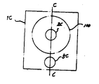
제2도는 종래의 자기 디스크 장치의 각종 분할 방식 설명도.2 is an explanatory diagram of various division methods of a conventional magnetic disk device.
제2a도는 하우징이 스핀들 축에 직교한 평명에서 분할되는 첫 번째 방식을 보인도.Figure 2a shows a first way in which the housing is divided in flatness perpendicular to the spindle axis.
제2b도는 하우징이 디스크 팩의 스핀들과 헤드 포지셔너의 스핀들과의 사이에 있는 평명에서 상측과 하측으로 분할되는 두 번째 방식을 보인도.Figure 2b shows a second way in which the housing is divided up and down in flatness between the spindle of the disc pack and the spindle of the head positioner.
제2c도는 하우징이 디스크 팩의 스핀들 중심 및 헤드 포지셔너의 스핀들 중심을 통과하는 평명에 의하여 좌·우로 분할되는 세 번째 방식을 보인도.2c shows a third way in which the housing is divided left and right by a plane passing through the spindle center of the disc pack and the spindle center of the head positioner.
제2d도는 하우징이 헤드 포지셔너의 스핀들을 통과하는 평면에 의하여 외판과 커버로 분할되고 하우징의 측벽을 대각선으로 가로지르는 네 번째 방식을 보인도.2d shows a fourth way in which the housing is divided into a shell and a cover by a plane through the spindle of the head positioner and diagonally across the side wall of the housing.
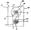
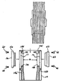
제3도는 본 발명의 실시예의 자기 디스크 장치의 분할 구조를 도시한 개요도.3 is a schematic diagram showing a partition structure of the magnetic disk device according to the embodiment of the present invention.
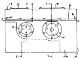
제4도는 하우징의 기밀을 유지하기 위하여 외판과 커버서로가 결속되어 있는 방식을 설명한, 본 발명에 따른 자기 디스크 장치의 정면도.4 is a front view of the magnetic disk apparatus according to the present invention, illustrating the manner in which the outer plate and the cover passage are bound to maintain the airtightness of the housing.
제5도는 커버 상부에서 바라본, 본 발명에 따른 자기 디스크 장치의 평면도.5 is a plan view of the magnetic disk apparatus according to the present invention as viewed from the top of the cover.
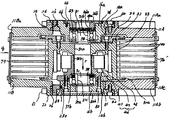
제6도는 자기 디스크 및 자기 헤드 포지셔너의 위치를 설명한, 제5도의 평면 x-x을 따라 취한 단면도.6 is a cross-sectional view taken along the plane x-x of FIG. 5, illustrating the position of the magnetic disk and the magnetic head positioner.
제7도는 디스크 팩의 스핀들이 외판에 지지되어 있는 방식을 설명한, 제4도의 평면 y-y을 따라 취한 단면도.FIG. 7 is a cross-sectional view taken along the plane y-y of FIG. 4, illustrating how the spindle of the disc pack is supported on the outer plate.
제8도는 자기 헤드 포지셔너의 스핀들이 외판에 지지되어 있는 방식을 설명한, 제4도의 평면 z-z을 따라 취한 단면도.FIG. 8 is a cross-sectional view taken along the plane z-z of FIG. 4 illustrating the manner in which the spindle of the magnetic head positioner is supported on the outer plate.
제9도는 디스크 팩을 틀에 부착하는 요령의 설명도.9 is an explanatory diagram of a trick of attaching a disk pack to a mold.
제10도는 커버를 하우징의 외판에 결합하는 요령의 설명도.10 is an explanatory view of a point of coupling the cover to the outer plate of the housing.
본 발명은 자기 디스크 메모리 장치에 관한 것이고, 특히 자기 디스크 팩 및 자기 헤드 포지셔너(positioner)를 지지하는 개선된 구조를 지닌 하우징에 관한 것이다.The present invention relates to a magnetic disk memory device, and more particularly to a housing having an improved structure for supporting a magnetic disk pack and a magnetic head positioner.
자기 디스크 장치는 서로 소정의 간격을 지니고 떨어져 있고 스핀들에 동축적으로 부착된 다수의 자기 디스크로 이루어진 자기 디스크 팩과 각각이 자기 헤드를 수반하는 다수의 아암을 지닌 자기 헤드 포지셔너를 가진다. 아암들과 디스크들은 디스크들 사이의 공간에서 각 아암들에 번갈아 위치 배열되어 있고, 각 아암들의 한끝은 두 번째 스핀들 상에 고정 되어 있다. 두 번째 스핀들 앞뒤로 축의 일정 각도록 회전하면서, 각 자기 헤드들은 트랙의 정보를 리이드 또는 라이트 하기 위하여 해당하는 디스크 표면에 형성되는 요구된 자기 트랙위로 위치된다.The magnetic disk device has a magnetic disk pack consisting of a plurality of magnetic disks spaced apart from each other and coaxially attached to the spindle, and a magnetic head positioner with a plurality of arms each carrying a magnetic head. Arms and disks are arranged alternately on each arm in the space between the disks, one end of each arm being fixed on the second spindle. Rotating some axis of the axis back and forth to the second spindle, each magnetic head is positioned over the required magnetic track formed on the corresponding disk surface to read or write the track's information.
현재의 자기 디스크 장치의 기술 추세로는 주로 자기 디스크의 표면에 저장된 메모리 밀도를 증가시키는 것이고, 저장 메모리에 짧은 액세스 시간을 만드는 것이다. 다른 한편, 전자 장치의 소형화 추세로 인하여 전자 장치에서의 자기 디스크에 할당된 공간을 작게하고 있다. 그래서 회경 21cm, 내경 10cm를 지닌 자기 디스크 장치들에 있어서 디스크 표면상에 메모리 트랙들의 트랙밀도는 1,000tpi(track/inch)에 까까우며 디스크의 회전속도는 3,600rpm정도이다.The current trend in magnetic disk devices is to increase the memory density stored on the surface of the magnetic disk and to make short access times to the storage memory. On the other hand, due to the trend toward miniaturization of electronic devices, the space allocated to magnetic disks in electronic devices is reduced. Thus, in magnetic disk devices having a diameter of 21 cm and an inner diameter of 10 cm, the track density of memory tracks on the disk surface is close to 1,000 tpi (track / inch) and the rotation speed of the disk is about 3,600 rpm.
디스크 및 자기 헤드의 소모(닳음) 및 홈이 생기지 않도록 자기 헤드가 디스크 표면에 접촉되지 않아야한다. 그러나 자기 헤드의 감도를 증가시키고 비트를 저장한 자기 영역을 감소시켜서 자기 트랙에서 비트밀도를 높이기 위하여 자기 헤드와 디스크 표면과의 사이에 거리를 유지하는 것이 바람직하다.The magnetic head should not touch the disk surface to avoid the wear and tear of the disk and magnetic head. However, it is desirable to maintain the distance between the magnetic head and the disk surface in order to increase the sensitivity of the magnetic head and reduce the magnetic area storing the bits to increase the bit density in the magnetic track.
자기 헤드와 디스크 표면사이의 갭을 플라밍(flying)높이라고 부른다. 현재의 장치에서 플라밍 높이는 약 0.2μm정도이다. 더욱이 자기 헤드의 일정한 감도를 유지하여 장치의 동작을 안정하게 하기 위하여 플라밍 높이가 일정하게 유지되어야 한다. 따라서 고속으로 회전하는 자기 디스크를 사이의 플라밍 높이를 일정하게 유지하여 약 2.5μm의 좁은 폭을 갖는 예정된 자기 트랙의 위치로 정확하게 자기 헤드를 설정하는 것은 어렵지만 매우 중요한 일이다.The gap between the magnetic head and the disk surface is called the flaming height. In current devices, the flaming height is about 0.2 μm. Moreover, the flaming height must be kept constant in order to maintain a constant sensitivity of the magnetic head to stabilize the operation of the device. Therefore, it is difficult but very important to correctly set the magnetic head to the position of the predetermined magnetic track having a narrow width of about 2.5 μm by keeping the flaming height constant between the magnetic disks rotating at high speed.
자기 헤드와 자기 트랙사이의 상대위치를 일정치로 정확하게 유지하기 위하여, 자기 디스크 팩의 스핀들 및 자기 헤드 포지셔너의 스핀들의 운동을 안정하고 매끄럽게 하게 하는 것이 중요하다.In order to accurately and accurately maintain the relative position between the magnetic head and the magnetic track, it is important to make the movement of the spindle of the magnetic disk pack and the spindle of the magnetic head positioner stable and smooth.
스핀들 및 하우징을 지지하는 지지 메카니즘은 자기 디스크 장치들용의 중요한 메카니즘들중의 하나이다. 자기 디스크 팩 및 이들 메카니즘 지지용 하우징은 그들을 먼지 및 습기로부터 보호하기 위하여 그들의 주변 공간을 밀폐시키는 콘데이너와 같은 기능을 한다. 따라서, 디스크팩의 하우징의 설계는 자기 디스크 장치들의 능력을 개선시키는 것이 중요하다. 설계 또한 자기 디스크 장치를 조립하고 조정하기 위한 경비와 관계가 있다.The support mechanism for supporting the spindle and the housing is one of the important mechanisms for magnetic disk devices. Magnetic disk packs and housings for supporting these mechanisms function like containers that seal their surrounding space to protect them from dust and moisture. Therefore, the design of the housing of the disk pack is important to improve the capability of the magnetic disk devices. The design also relates to the cost of assembling and adjusting the magnetic disk device.
일반적으로, 자기 디스크 팩의 하우징 안에 디스크 팩을 부착하기 위하여 그것을 외판(shell)과 커버(cover)로 분할한다. 외판은 디스크 팩 및 자기 헤드 포지셔너를 역학적으로 지지하는 반면에 커버는 자기 디스크 및 다른 메카니즘을 통하여 설치되는 외판 개구를 밀폐시킨다. 제1도는 자기 디스크 장치의 구성을 도시한 일부 절취사시도이다. 하우징 1은 외판 1A와 커버 1B로 분할된다. 그리고 외판과 커버는 라인 1a에서 서로 연결된다. 전체 장치는 제1도에 도시한 부분과 제1도의 일부와 대칭구조를 지닌 또 다른 부분으로 이루어져 있다.Generally, in order to attach a disk pack into the housing of the magnetic disk pack, it is divided into a shell and a cover. The outer shell dynamically supports the disk pack and the magnetic head positioner, while the cover seals the outer shell opening, which is installed through the magnetic disk and other mechanisms. 1 is a partially cutaway perspective view showing the configuration of a magnetic disk device. The housing 1 is divided into an
제1도에서 1A는 자기 디스크 팩의 스핀들 2 및 자기 헤드 포지셔너 3지지용 하우징의 외판부이다. 스핀들 2주변에 여섯 개의 자기 디스크 100이 쌓여져 있다. 디스크의 수는 장치에 저장되어야 하는 메모리의 크기에 따라 변화될 수 있다. 스핀들 2는 볼 베어링 7 및 8에 의하여 그 두 끝에 지지된다. 이들 베어링의 회전을 자유자재로 하게 하는 반면에 이들 베어링은 이들에 의하여 분리되는 내부 공간과 외부 공간과의 사이의 밀폐를 유지하는 강유체씰(ferrofluidic seal)을 포함한다. 자기 디스크들 100은 서로 일정한 거리를 가지고 떨어져 있고 스핀들 2의 한 끝에 부착된 DC모터 4에 의하여 스핀들 2의 주변을 회전하게 된다. 자기헤드 포지셔너 3의 구조는 자기 디스크 팩의 구조와 비슷하다. 그것은 스핀들 5에 고정된 아암들을 가지며 볼 베어링 9 및 10에 의하여 지지된다. 스핀들 5는 요구한 각도로 좌·우로 그의 축 둘레를 회전하기 위하여 보이스 코일 모터 6에 의하여 구동된다. 그래서 아암들에 의하여 지지되는 자기 헤드(도시되어 있지 않음)를 자기 디스크상의 요구한 위치로 가져오게 된다.1A in FIG. 1 is the outer plate portion of the housing for supporting the
일반적으로, 자기 디스크 팩 및 자기 헤드 포지셔너는 제1도에 도시한 바와 같이 베어링들에 의하여 그들의 양 끝에 지지된다. 그러나 더블-엔디드(double-ended) 구조는 싱글-엔디드(single-ended)구조에 비하여 장치의 동작이 더욱 안정하기 때문에, 더블-엔디드 구조는 스핀들의 한 끝에 장착된 하나에 베어링으로만 스핀들을 지지하는 싱글-엔디드 구조보다 우수하다. 특히, 스핀들의 축의 경사 예를들면 수직 또는 수평으로 기울어짐에 상관없이 사용될 수 있기 때문에 전자가 더욱 좋다. 그러나 어떤 경우에는 자기 헤드 포지셔너의 스핀들이 싱글-엔디드 구조일 수 있다. 다음 설명에서는 더블-엔디드 구조를 설명할 것이다. 그러나 그러한 설명에서는 싱글-엔디드 구조에도 쉽게 적용될 수 있다는 것이 명백하게 될 것이다.In general, magnetic disk packs and magnetic head positioners are supported at their ends by bearings as shown in FIG. However, because the double-ended structure makes the operation of the device more stable than the single-ended structure, the double-ended structure supports the spindle only with a bearing mounted at one end of the spindle. It is better than single-ended structure. In particular, the former is better because it can be used regardless of the inclination of the axis of the spindle, for example vertically or horizontally. In some cases, however, the spindle of the magnetic head positioner may be a single-ended structure. The following description will describe the double-ended structure. However, it will be evident that such descriptions can be easily applied to single-ended structures.
상기 설명된 바와 같이 디스크 팩을 부착하기 위하여 자기 디스크 팩의 하우징(이후에는 간단히 하우징이라함)은 외판과 커버 두 부분으로 분할된다. 종래 장치의 하우징은 하우징의 절취에 따라 몇가지 형태로 요약되고, 그것은 두 부분으로 분할되는 하우징을 가로지르는 절취 평면과 관계가 있다. 전형적인 절취방식을 제2(a)도 내지 제2(d)도에 모식적으로 도시하였다.As described above, in order to attach the disc pack, the housing of the magnetic disc pack (hereinafter simply referred to as the housing) is divided into two parts: the outer plate and the cover. The housing of a conventional device is summarized in several forms upon cutting of the housing, which relates to the cutting plane across the housing which is divided into two parts. Typical cutting methods are schematically illustrated in FIGS. 2 (a) to 2 (d).
제2도는 종래의 자기 디스크 장치의 각종 분할방식 설명도이다. 제2(a)도는 첫 번째 방식이고, 디스크들 100, 디스들의 스핀들 2A 및 자기 헤드 포지셔너(완전히 도시되어 있지 않음)를 하우징 1A의 단면도이다. 아우징 1A는 라인 a-a에 있는 페이지에 수직으로 위치된 경계면에서 좌·우로 역학적으로 분할된다. 자기 디스크들 100, 그들의 스핀들 2A 및 자기 헤드 포지셔너의 스핀들 5A를 하우징 1A에 설치한 후에, 하우징의 좌·우를 서로 결속시킨다. 그런 방식의 상세한 자기 디스크 장치가 1982년 2월 9일에 공고된 Bernett 공저의 미국 특허번호 4,315,288에 실려져 있다.2 is an explanatory diagram of various division methods of a conventional magnetic disk device. FIG. 2 (a) is the first way, and the
그런 구조에서, 자기 디스크 팩 및 자기 헤드 포지셔너(이후에는 간단히 각각 디스크 팩 및 헤드 포지셔너라 한다)의 스핀들 양끝 각각이 하우징의 반쪽의 반대에 속하는 한쌍의 벽에 의하여 지지된다.In such a structure, each of the spindle ends of the magnetic disk pack and the magnetic head positioner (hereafter simply referred to as the disk pack and head positioner respectively) is supported by a pair of walls opposite to the half of the housing.
그래서 그의 양끝에서 스핀들을 지지하는 베어링들의 중심들이 서로 편심되기 쉬워진다. 그리고 각각의 요구한 위치에서 자기 헤드 및 자기 디스크를 탄탄하게 유지하기 위하여 이들 베어링의 조정은 매우 임계적이다. 더욱이, 만약 하우징의 반쪽들이 서로 다른 제조 롯트(lot)이라면, 때때로 하우징의 두 반쪽의 롯트들 사이의 열팽창 계수의 차로 인하여 열적 오프-트랙(off-track)을 일으킨다는 문제가 있다.Thus the centers of the bearings supporting the spindles at both ends thereof tend to be eccentric with each other. And the adjustment of these bearings is very critical to keep the magnetic head and the magnetic disk firm at each required position. Moreover, if the halves of the housing are of different manufacturing lots, there is a problem that sometimes causes thermal off-track due to the difference in coefficient of thermal expansion between the lots of the two halves of the housing.
그런단점을 해결하기 위하여 때때로 싱글-엔디드형 구조를 선택(채택)하다. 그러한 상기 상술해 왔었던 바와 같이, 스핀들의 지지 안정도가 불충분하다. 특히 스핀들의 수 또는 디스크의 회전 속도가 증가될 때 이 문제가 심각하다. 제2(b)도는 하우징의 두 번째 분할 방식을 설명한 하우징 단면도이다. 도에 도시한 바와같이 하우징은 디스크 팩의 시핀들 2B와 헤드 포지서너의 시핀들 5B와의 사이를 기준하여 상하로 분할된다. 하우지에 대하여 상·하 도는 좌·우라는 용어는 임시 웅변적이지만 그런 용어는 동일성을 위하여 다음 서술에서도 계속 사용되어질 것이다. 절취평면은 라인 b-b를 따라 페이지에 수직으로 위치해 있다. 제1도에 도시한 장치는 이 방식이다. 제2(b)도의 경우에서, 슬롯트 4B는 하우징 1B의 상부 절반의 벽들의 양 반대측면에 있다. 그 위치에 스핀들을 설정하기 위하여 슬롯트 4B가 라인 b-b를 따라 개구 가장자리로 부터 스핀들 2B의 위치까지 절취된다. 도에 있어서, 스핀들 5B는 싱글-엔디드형이어서 슬롯트가 스핀들 5B에는 불필요하다. 그너나 안약 스핀들 5B가 그의 양 끝에 의하여 지지된다면, 하우징의 상부 절반에 하우징과 같은 것 4B의 하부 절반에서의 또다른 한쌍의 슬롯트를 제공할 필요가 있다.In order to solve such drawbacks, single-ended structures are sometimes chosen. As mentioned above, the support stability of the spindle is insufficient. This problem is particularly acute when the number of spindles or the rotational speed of the disks are increased. 2 (b) is a cross-sectional view of the housing illustrating the second dividing method of the housing. As shown in the figure, the housing is divided up and down on the basis of the pins 2B of the disc pack and the pins 5B of the head positioner. The terms upper, lower, left, and right for HOWE are temporary eloquent, but such terms will be used throughout the following description for the sake of identity. The cutting plane is located perpendicular to the page along line b-b. The apparatus shown in FIG. 1 is this way. In the case of Figure 2 (b), slot 4B is on both opposite sides of the walls of the upper half of housing 1B. Slot 4B is cut along the line b-b from the opening edge to the position of spindle 2B to set the spindle in that position. In the figure, spindle 5B is single-ended so that no slot is necessary for spindle 5B. However, if the eye spindle 5B is supported by both ends thereof, it is necessary to provide another pair of slots in the lower half of the same 4B as the housing.
제2(b)도의 방식에서, 디스크 팩의 시핀들 2B 및 헤드 포지셔너의 스핀들 5B는 각각 하우징의 다른 절반에 부착되고 그들 서로는 결속된다. 그래서 자기 헤드와 디스크와의 사이의 상대 위치를 유지하기 위한 조정은 매우 임계적 이어서, 방식 1에서 서술한 열적 오프-트랙의 문제를 해결하지 못하였다. 그리고 하우징이 하우징의 양측벽에 절취된 슬롯트를 가져서 하우징의 강성이 부족하다. 그리고 하우징의 부품수가 증가하므로 조립경비 역시 증가한다.In the manner of FIG. 2 (b), the seapins 2B of the disc pack and the spindle 5B of the head positioner are each attached to the other half of the housing and are bound to each other. Thus, the adjustment to maintain the relative position between the magnetic head and the disk is very critical, which does not solve the problem of thermal off-track described in scheme 1. In addition, the housing has slots cut in both side walls of the housing, so the rigidity of the housing is insufficient. And as the number of parts in the housing increases, the assembly cost also increases.
제2(c)도는 하우징의 세 번째 방식의 측면도이다. 하우징 1C는 디스크 팩의 스핀들 2C의 중심과 헤드 포지셔너의 스핀들 5C의 중심을 통과하는 라인 c-c로 표시한 평면에 의하여 좌·우 절반으로 분할 된다. 제2(c)도의 방식에서 스핀들 2C 및 5C를 지지하는 호울은 두 개의 반원으로 분할된다. 이것은 일하는데 어려움을 주어서 이들 두 개의 반원을 조합 함으로써 형성되는 원의 원형성의 정확성을 떨어뜨린다. 스핀들 2C 및 5C를 지지하는 하우징의 강성이 저하되고, 디스크 팩은 때때로 떨림을 일으킨다. 열적 오프-트랙을 가로 지르지 아니한다. 더욱이, 하우징의 좌·우 절반의 결속 료면이 단일 평면은 아니다. 왜냐하면 그것이 스핀들에 대해 절취한 반원을 가지기 때문이다. 이것은 주변 공간으로부터 디스크 팩을 밀폐하는 하우징의 두 절반 사이에 밀폐수단을 삽입하는데 많은 어려움을 준다. 그래서, 밀폐성이 떨어진다.Figure 2 (c) is a side view of a third manner of housing. The
제2(d)도는 하우징의 네 번째 방식의 측면도이고, 도에서 하우징 1D는 헤드 포지셔너의 스핀들 5D를 통과하는 평면 d-d에 의하여 외판 1D'와 커버 1D'로 분할되고 하우징의 측면을 대각선으로 가로 지른다. 이방식에서, 디스크 팩의 스핀들 2D를 삽입하기 위한 측면 슬롯트 4D가 필요하다. 제2(d)도의 방식에서, 스핀들 5D는 싱글-엔디드형이다. 그런 방식은 예를들면 1987년 9월 8일에 공고된 Biermeier 공저의 미국 특허번호 4,692,827에 상세히 서술되어 있다. 이 방식은 장치의 조립에서의 어려움을 덜어준다. 그러나 방식2(b)에서 서술한 바와 같은 난점은 아직 남아 있다.FIG. 2 (d) is a side view of the fourth manner of the housing, in which the housing 1D is divided into the outer shell 1D 'and the cover 1D' by a plane dd passing through the spindle 5D of the head positioner and crosses the sides of the housing diagonally. . In this way, a side slot 4D is required for inserting the spindle 2D of the disk pack. In the manner of Figure 2 (d), the spindle 5D is single-ended. Such a method is described in detail, for example, in US Pat. No. 4,692,827 to Biermeier, published September 8, 1987. This approach eliminates the difficulty in assembling the device. However, the difficulties as described in Method 2 (b) remain.
상술해 왔던 바와 같이, 종래 하우징의 구조를 디스크 장치의 조립을 쉽게 하는 방향으로 이끌음으로써 조립된 장치의 정확성을 향상시키는데 있다. 따라서 많은 경우에 있어서, 스핀들 특히 헤드 포지셔너의 스핀들이 싱글-엔디드형이다. 그리고 더블-엔디드 스핀들이 교점 평면에 의하여 두 부분으로 분할되는 한쌍의 호올에 의하여 지지되거나 적어도 그 호올이 스핀들을 삽입하기 위하여 슬롯트에 의하여 그의 한측에 절취된다. 이것은 하우징의 강성을 저하시키고 상기 언급한 여러 가지 문제를 야기 시킨다.As described above, the conventional housing is designed to improve the accuracy of the assembled device by guiding the structure of the disk device in a direction that facilitates the assembly of the disk device. In many cases, therefore, the spindle, in particular the spindle of the head positioner, is single-ended. And the double-ended spindle is supported by a pair of hools divided into two parts by the intersection plane, or at least the hoole is cut off on one side by the slot to insert the spindle. This lowers the rigidity of the housing and causes various problems mentioned above.
따라서 본 발명의 목적은 고역학적 강성을 갖는 자기 디스크 팩 장치용 하우징 및 자기 디스크 상에 요구한 위치로 정확하게 자기 헤드를 위치하기에 알맞는 하우징을 제공하고, 고 메모리 밀도와 고동작 속도를 갖느느 자기 장치를 실용화 시키는 것이다.It is therefore an object of the present invention to provide a housing for a magnetic disk pack device having high mechanical rigidity and a housing suitable for accurately positioning a magnetic head in a required position on a magnetic disk, and having a high memory density and a high operating speed. It is to make the magnetic device practical.
본 발명의 다른 목적은 다수의 자기 디스크들을 수용할 수 있는 자기 디스크 장치를 제공하는 것이다.Another object of the present invention is to provide a magnetic disk device capable of accommodating a plurality of magnetic disks.
본 발명의 또 다른 목적은 고역학적 강도를 갖는 그의 양끝으로 자기 디스크 팩의 스핀들을 지지할 수 있는 하우징의 구조를 제공하는 것이다.It is another object of the present invention to provide a structure of a housing capable of supporting the spindle of a magnetic disk pack with its ends having high mechanical strength.
본 발명의 또 다른 목적은 고역학적 강성을 갖는 자기 헤드 포지셔너의 스핀들을 지지할 수 있는 하우징의 구조를 제공하는 것이다.It is another object of the present invention to provide a structure of a housing capable of supporting the spindle of a magnetic head positioner having high mechanical rigidity.
본 발명의 궁극적인 목적은 자기 디스크 장치의 스핀들 지지용 분할형 하우징 및 상기 목적을 실현할 수 있는 관련 수단을 제공하는 것이다.The ultimate object of the present invention is to provide a split housing for spindle support of a magnetic disk device and associated means for realizing the above object.
상기 목적들은 하우징을 자기 디스크 팩 및 자기 헤드 포지셔너 지지용 직각 튜브와 같은 구조를 지닌 외판과, 자기 디스크 팩 및 자기 헤드 포지셔너가 통하여 설치되어 있는 틀의 개구를 커버하는 외판으로 분할함으로써 얻어진다. 본 발명에 의한 하우징의 분리 형태는 제3도에 도시되어 있다. 제3도는 본 발명의 하우징의 측면도이다. 도에서 알 수 있는 바와 같이, 라인 e-e로 표시한 절취평면은 부싱(bushing) 지지부를 횡단하지 아니한다. 외판은 스핀들이 지지되어야 하는 위치에서 완전 원형 지지호올을 갖는다.The objects are obtained by dividing the housing into an outer plate having a structure such as a right angle tube for supporting the magnetic disk pack and the magnetic head positioner, and an outer plate covering the opening of the frame through which the magnetic disk pack and the magnetic head positioner are installed. The separation form of the housing according to the invention is shown in FIG. 3. 3 is a side view of the housing of the present invention. As can be seen in the figure, the cutting plane, indicated by the line e-e, does not traverse the bushing support. The outer shell has a fully circular support hole in the position where the spindle is to be supported.
지지 호올들은 그의 중심에 있는 볼 베어링을 지지하는 원통형 부싱의 주변에 결합시키기 위한 직경을 갖는다. 하나의 보오링 공정으로 서로 맞대고 있는 외판의 측벽들 각각에 지지호올이 형성된다. 따라서, 호올은 완전 원형으로 형성되고 지지호올의 쌍의 중심들이 서로 동심적으로 배열될 수 있다. 스핀들은 지그(jig)로 그의 위치에 고정시키는 동안에 외판의 외칙으로부터 관련 지지호올 안으로 볼 베어링 및 부싱을 삽입하고 고정시킨다.The support holes have a diameter for engaging around the cylindrical bushing that supports the ball bearing at its center. A support hole is formed on each of the sidewalls of the outer plate facing each other by one boring process. Thus, the hool may be formed in a completely circular shape and the centers of the pairs of support hools may be arranged concentrically with each other. The spindle inserts and locks the ball bearings and bushings from the outer rules of the shell into the associated support holes, while the spindle is fixed in its position with a jig.
동시에 스핀들의 양끝이 볼 베어링의 내부링 안으로 삽입된다. 그래서 스핀들을 안정하고 매끄럽게 회전할 수 있게 하는 베어링들을 그의 중심에 동축적으로 고정한다. 그런 구조는 자기 디스크 팩 및 자기 헤드 포지셔너 둘을 지지하는데 쓰인다.At the same time both ends of the spindle are inserted into the inner ring of the ball bearing. Thus, the bearings are fixed coaxially to their center, which allows the spindle to rotate stably and smoothly. Such a structure is used to support both the magnetic disk pack and the magnetic head positioner.
외판과 같은 튜브의 가장자리는 그 부분 또는 슬롯트에서도 절취하지 않았었다. 그래서, 디스크 팩 및 헤드 포지셔너의 정확한 위치를 확보하기 위하여 외판은 고역학적 강성을 지닌다. 커버는 외부 공간과 디스크팩을 밀폐시키기 위하여 외판과 결속된다. 외판과 커버의 결속 표면이 평면이고 그 부분 또는 슬롯트에서도 절취하지 않았었기 때문에 그들 사이에 팩킹을 삽입하는 것이 쉽다 그래서 기밀 밀폐를 쉽게 할 수 있다.The edges of the tube, such as the shell, were not cut off at that portion or slot. Thus, the outer shell has high mechanical rigidity in order to secure the correct position of the disc pack and the head positioner. The cover is engaged with the outer plate to seal the outer space and the disc pack. Since the binding surface of the shell and the cover is flat and has not been cut off at that part or slot, it is easy to insert a packing between them so that an airtight seal can be easily made.
본 발명의 구조용 부품의 수는 최소이고, 조립이 쉽다, 그래서, 자기 디스크 장치의 경비가 떨어진다. 본발명의 이점은 다음 상세한 서술로부터 명백해질 것이다.The number of structural parts of the present invention is minimal and easy to assemble, so that the cost of the magnetic disk device is low. The advantages of the present invention will become apparent from the following detailed description.
우선 본 발명에 따른 하우징의 기본 구조를 제3도와 관련 하여 서술한다. 제3도는 디스크 팩과 헤드 포지셔너를 삽입하기 위하여 두 부분으로 분할되는 방식을 설명한 하우징의 측면도이다. 하우징 11은 도의 라인 e-e에 있는 페이지를 수직으로 가로 지르는 평면에서 외판 11A 및 커버 11B로 분할될 수 있다. 외판 및 커버는 직각 튜브와 같은 형태이다. 디스크 팩 및 헤드 포지셔너를 거기에 부착한 후에 그들을 제3도에 도시되어 있는 바와 같이 결속시켰다.First, the basic structure of the housing according to the present invention will be described with reference to FIG. 3 is a side view of the housing illustrating the manner in which it is divided into two parts for inserting the disc pack and the head positioner. The
서로 맛대는 외판 11A의 한쌍의 측벽에 디스크 팩 및 헤드 포지셔너의 스핀들 12 및 13을 각각 지지하기 위한 지지수단이 갖추어져 있다. 즉, 지지호올 14 및 15는 각 측벽에 있다. 이들 호올들은 반대 측벽에 있는 각 카운터부와 쌍을 이룬다.Supporting means for supporting the
지지호올 14의 쌍의 그의 양끝에서 스핀들 12를 지지하고, 지지호올 15의 쌍은 그의 양끝에서 스핀들 13을 지지한다. 스핀들 12는 디스크 100을 지지하고, 스핀들 13은 헤드 포지셔너의 아암 101을 지지한다. 이들 지지호올의 각 쌍은 서로맛대는 양 측벽의 구멍을 뚫는 보오링 공정으로 형성된다. 그래서 그 쌍의 각 지지호올의 중심들은 서로 완전히 동축적으로 배열된다. 이곳이 첫 번째 형태이고 본 발명의 하우징 구조의 첫 번째 이점이다.A pair of support holes 14 supports the
지지수단 각각은 한쌍의 원통형 부싱 16 또는 17과 각각의 부싱에 설치된 한쌍의 볼 베어링을 더 포함한다. 각 볼베어링은 부싱에 의하여 지지되고 외판의 외측으로부터 지지호올안으로 삽입된다. 따라서, 짝을 이룬 볼 베어링의 중심들은 서로 쉽게 동축적으로 배열된다. 이것이 본 발명의 하우징 구조의 두 번째 형태이고 이점이다.Each support means further comprises a pair of
제3도에서 알 수 있는 바와 같이, 지지호올 14 및 15는 외판 형태의 튜브의 밑바닥을 향하여 외판의 개구 가장자리 e-e로부터 떨어져 위치되어 있다. 그래서 양 개구 가장자리 e-e또는 지지호올 13 및 14상에 절취면 또는 슬롯트가 모두 없다. 이것이 본 발명의 세 번째 형태이고 종래의 것들에 비하여 스핀들을 지지하는 강성 구조의 하우징을 제공할 수 있기 때문에 본 발명의 세 번재 이점이다.As can be seen in FIG. 3, the
또한, 지지호올이 완전 원형으로 형성될 수 있어서 베어링들의 중심들이 서로 동축적으로 배열되서 탄탄하게 지지된다. 이것이 본 발명의 네 번째 형태 및 이점이다.In addition, the support hose can be formed in a completely circular shape so that the centers of the bearings are arranged coaxially with each other to be firmly supported. This is the fourth form and advantage of the present invention.
절취 평면 e-e가 스핀들의 지지부를 횡단하지 아니하기 때문에, 외판과 커버와의 합친 표면은 단순 평면이다. 절취면 또는 슬롯트를 제공하는 것이 불필요하다. 이것이 외판과 커버와의 사이에 밀폐수단을 삽입하는 것을 쉽게 해준다는 것이다. 그래서 하우징의 밀폐를 쉽게할 수 있다. 이것 또한 본 발명의 이점이다.Since the cutting plane e-e does not traverse the support of the spindle, the combined surface of the shell and the cover is a simple plane. It is not necessary to provide a cutout or slot. This makes it easy to insert the sealing means between the shell and the cover. Thus, the housing can be easily sealed. This is also an advantage of the present invention.
디스크 팩과 헤드 포지셔너의 스핀들용 두 지지수단을 비슷한 구조로 형성할 수 있다는 것이 쉽게 이해될 것이다. 이것은 하우징을 제조하는 단계가 종래에 비하여 쉽고 간단하다는 것을 의미한다. 이것은 본 발명의 부가적이 이점이다.It will be readily understood that the two support means for the spindle of the disc pack and the head positioner can be formed in a similar structure. This means that manufacturing the housing is easier and simpler than in the prior art. This is an additional advantage of the present invention.
제3도 및 상기 서술에서, 절취평면 e-e는 스핀들 12 및 15의 중심을 연결하는 라인과 나란하게 도시되어 있다. 그러나 라인 e-e가 두 중심을 연결하는 라인에 평행할 필요는 없다는 것을 이해할 것이다. 또한 분리선 e-e는 직선일 필요는 없다. 이것은 접합 표면을 평탄한 평면에 형성하지 않아도 된다는 것을 의미한다. 그러나 직선과 평탄한 평면이 가장 실용적이다.In FIG. 3 and above, the cutting plane e-e is shown alongside the line connecting the centers of the
다음에 본 발명에 따른 하우징의 상세한 구조를 제4도 내지 제8도와 관련하여 설명할 것이다. 실제로 하우징은 여러 부품, 예를들면 인쇄회로판 및 그들을 지지하거나 구동시키는 여러 가지 수단들로 이루어졌다. 그러나 도에서는 간단하게 하기 위해 본 발명에 관련있는 부분만을 도시해서 본 발명을 확실하게 이해하게 한다. 제4도는 본 발명에 따른 자기 디스크장치의 정면도, 제5도는 평면도, 제6도는 횡단면도이다. 제4도에서 하우징 커버 11B(이후에는 간단히 커버로 언급함)와 하우징 외판 11A(이후에는 간단히 외판으로 언급함)가 분리선 e-e에서 서로 결합된다. 커버 11B의 플랜지 22는 나사 21에 의하여 외판 11A의 가장자리에 고정된다. 커버 11B에 하우징에서의 장치를 관찰하고 조정하는데 쓰이는 개구들이 갖추어져 있다. 이들 개구들(제6도에 27 및 29로 표시된)은 커버판 73 및 75로 밀폐되고 커버 11B의 본체를 나사로 조인다. 지지수단을 보인 외판 11A의 앞벽(제4도)상에서 이들은 부싱 16,17이고 그드을 나사로 고정시킨다. 그들을 후에 제7도 및 제8도와 연관하여 상세히 설명할 것이다.Next, a detailed structure of the housing according to the present invention will be described with reference to FIGS. 4 to 8. In practice the housing consists of several components, for example a printed circuit board and various means for supporting or driving them. In the drawings, however, only parts relevant to the present invention are shown for the sake of simplicity, so that the present invention is clearly understood. 4 is a front view of the magnetic disk apparatus according to the present invention, FIG. 5 is a plan view, and FIG. 6 is a cross sectional view. In FIG. 4, housing cover 11B (hereinafter simply referred to as cover) and
제6도는 제5도의 평면 x-x를 따라 취한 장치의 횡단면도이다. 디스크 100은 스핀들 12에 의하여 그의 중심이 지지되고 스핀들 축 둘레를 회전한다. 헤드 포지셔너 101은 스핀들 13주변에 장착된 다수의 아암103(하나만 표시함)을 가지고, 화살표 p-p로 도시한 바와 같이 스핀들 13의 축 주변의 좌·우로 회전할 수 있다. 각 아암 103은 그의 끝에 있는 자기 헤드 102를 수반한다. 단자 105는 제어장치(도시되어 있지 않음)로부터 서보 신호를 수신하고 그들을 도선 106을 거쳐서 보이스 코일 모터 104로 전송한다. 서보신호를 수신하면 보이스 코일 모터 104는 스핀들 13주변을 소정의 각으로 회전하도록 아암 103을 구동시킨다.FIG. 6 is a cross sectional view of the device taken along plane x-x of FIG. The
그래서, 자기 헤드는 디스크 100의 표면상에 있는 예정된 자기 트랙(도시되어 있지 않음)위에 위치된다. 보이스 코일 모터 104로 아암 또는 스핀들 13을 구동시키는 메카니즘은 도에 도시되어 있지 아니한다. 그것들은 종래의 것들이고 본 발명과 직접 관련이 없어 더 이상의 설명은 생략한다.Thus, the magnetic head is placed on a predetermined magnetic track (not shown) on the surface of the
외판 11A 미치 커버 11B는 다이캐스팅으로 제작한 알루미늄으로 제조된 모양과 같은 튜브형태이다. 외판의 밑표면 11Ac에 개구 28 및 30이 있다. 그것들은 디스크 및 헤드 포지셔너를 관찰하거나 조정하는데 쓰인다. 이들 개구들은 커버판 74 및 76에 의하여 밀폐되고 외판 11Ac의 본체를 나사로 조인다. 각 개구 27,29,28, 및 30의 주변에는 홈 18이 있다.
이들 홈 각각은 고무로 만든 링 씰(Ring seal)(도시되어 있지 않음)을 포함하고 밀폐를 유지한다. 제3도의 절취 평면 e-e인 커버 11B 및 외판 11A의 개구가장자리는 튜브의 밑표면에 평행한 평면에서 끝나게 된다. 그들은 하우징 근cj에서 서로 결속된다. 제6도에서 알 수 있는 바와 같이, 커버와 외판과의 겨속표면들 사이에 고무로 만든 링 씽 23을 삽입한다. 커버 11B의 결속 표면상에 링 23을 설치하기 위한 홈이있다. 물론 이 밀폐메카니즘은 예를들면 가스킷(gastet)같은 어느 형태라도 좋다.Each of these grooves includes a ring seal (not shown) made of rubber and maintains a seal. The opening edges of cover 11B and
제7도 및 제8도는 각각 제4도에서의 라인 y-y와 구부러진 라인 z-z를 따라 취한 제4도의 장치의 횡단면도이다. 이들 도면들은 각각 헤드 포지셔너의 스핀들 13 및 디스크 팩의 스핀들 12의 지지 메카니즘을 보인 도면이다. 이들 실시에에서 여덟 개의 디스크 100은 스핀들 12주변에 동축적으로 배열되고 디스크팩은 구성한다. 디스크의 수는 장치에 저장되어야 하는 메모리의 크기에 따라 적당하게 변화시킬 수 있다.7 and 8 are cross-sectional views of the device of FIG. 4 taken along line y-y and curved line z-z in FIG. 4, respectively. These figures show the support mechanism of
제7도에 도시한 바와 같이, 스핀들 12의 각 끝은 샤프트 31이 된다. 스핀들 12의 직경은 두 스텝 벌지(step bulge) 31a 및 31b를 형성한 그의 중앙부에서 샤프트 31의 직경보다 더 크다. 각 디스크 100은 스페이서 33에 의하여 분할되고 서로 일정한 간격을 유지한다. 디스크 100 및 스페이서 33은 도에 도시한 바와같이 중공(hollow)구조를 갖는 원통형 허브(hub) 32의 외부 표면과 결합된다.As shown in FIG. 7, each end of the
허브 32의 한끝(하부끝)에 플랜지 32a가 있다. 디스크 100 및 스페이서 33은 번갈아 허브 32에 설치되어 있고 지지링 34로 플랜지 32a를 향하여 그들을 누르게 하여 고정된다. 하우징 링 34는 디스크의 스택위에 위치되고 나사 35로 허브 32에 죄어 있다. 그러한 디스크의 스택은 그의 상부 끝으로부터 스핀들 12상에 설치되고 스탭벌지 31a에 의하여 지지된다. 두 스텝벌지의 하부 31b의 직경은 상부의 직경보다 훨씬크고 원통형 허브 32의 내경은 상부의 내경과 같다. 그래서 허브 32는 디스크 팩을 형성하는 스핀들 12와 결합한다. 스텝벌지 31a와 허브 32의 내부표면을 눌러 고정시킨다. 샤프트 31의 상부 및 하부도 또한 볼 베어링 36 및 37의 내부링 36a 및 37a에 맞게 고정된다.At one end (lower end) of
그래서 스핀들 12는 볼 베어링 36 및 37에 의하여 각각 그 양 끝에 지지된다. 밀폐를 유지하도록 이들 볼베어링들은 각기의 내부링 36a,37a 및 외부링 36b,37b 사이에 강유체 씰(seal)로 가득 채워진다.The
허부 32의 중공 공간에다 DC모터 46을 설치한다. 모터 46은 고정자 47, 회전자 48 및 코일 49로 이루어져 있다. 회전자 48을 허브 32에 고정시킨다. 그래서 최종적으로 회전자 48 및 디스크 100을 스핀들 12에 고정시키고 그들은 스핀들 12의 축 둘레를 회전할 수 있다. 고정자 47 및 49가 지지요소 51에 의하여 지지 되고 나사 52로 부싱 16b에 고정시킨다. 부싱 16b를 나사 42로 외판의 측벽 11Ab에 더 고정시킨다. 그래서 마지막으로 고정자 47 및 코일 49를 외판의 벽 11Ab에 고정시킨다.Install DC motor 46 in the hollow space in the bottom 32. The motor 46 consists of a
상부 베어링 36 및 하부 베어링 37이 각각 원통형 부싱 16A 및 16b에 결속된다. 외판의 양측겹 11A 및 11B상에 각각 형성되는 지지호올 14a,14b의 내부 표면을 고정시키기 위하여 이들 부싱의 외부표면을 정확하게 완성시킨다. 볼 베어링들 36 및 37의 외부표면에 고정시키기 위하여 이들 부싱들의 내부 표면을 정확하게 완성시키는 동안에 이들 볼 베어링들의 중심들은 서로 동축적으로 정확하게 유지된다.The upper bearing 36 and the lower bearing 37 are engaged with the
하부 볼 베어링 37의 외부링 37b는 부싱 16b의 내부 플랜지에 의하여 지지된다. 상부 볼 베어링 36상에 벨레빌(velleville)스프링 43이 위치되고 벨레빌 스프링 43은 칼라링 44에 의하여 샤프트 31에 고정된다. 칼라링 44는 나사 45에 의하여 부싱 16a에 고정되고 부싱 16a는 나사 40에 의하여 외판의 측벽 11Aa에 더 고정된다. 그리하여 볼 베어링의 역회전을 줄이기 위하여 스핀들 12의 샤프트 31의 화살표 r로 지시한 방향으로 구동되게 된다.The outer ring 37b of the lower ball bearing 37 is supported by the inner flange of the
칼라링 44의 개구 끝 및 부싱 16b를 각각 판 50a 및 50b 끝으로 밀폐시킨다. 그들은 나사로 조이거나 페이스팅 등의 적당한 방법으로 각 위치에 고정시킨다. 그 일예를 제8도에 도시한다. 헤드 포지셔너 101의 구조는 상기 서술한 디스크 팩의 구조와 거의 유사하다. 제8도는 제4도에서 라인 z-z에 따른 장치의 횡단면도를 보인 것이다. 스핀들 13은 샤프트 60 및 볼 베어링 61,62를 포함한다. 디스크 팩을 쌓는 유사한 방식으로 아암 103을 쌓고 스핀들 13에 고정시킨다. 이들 볼 베어링에 강유체 씰 63이 갖추어져 있다. 볼베어링 61,62는 각각 원통형 부싱 17a,17b에 의하여 그의 외부에 각각 지지된다. 지지호올 15a 및 15b에 고정시키기 위하여 이들 부싱의 외부 표면을 정확하게 완성시킨다.The opening end and the
그래서 이들 볼 베어링의 축이 서로 동축이 되도록 정확하게 위치된다. 부싱 17a 및 17b를 나사 66,67로 측벽 11Aa, 11Ab에다 죄어 고정시킨다. 샤프트 60은 벨레빌 스프링 68 및 끝 조각(end piece)69에 의하여 화살표 s로 지시한 방향으로 움직이게 된다. 끝 조작 69를 나사 70으로 부싱 17a에다 죄어 고정시킨다. 부싱 17b의 개구 끝은 나사 72에 의하여 부싱 17b에 조여지는 커버판 71호 밀폐된다. 이들 요소들의 효과 및 구조는 제7도와 관련하여 서술한 디스크 팩과 비슷하다. 이들 디스크 팩 및 헤드 포지셔너에 대한 더자세한 것은 본 발명과는 관련이 없어 삭제 한다.The axes of these ball bearings are thus positioned precisely so that they are coaxial with each other. Secure bushings 17a and 17b to side walls 11Aa and 11Ab with
그리고, 디스크 팩 및 헤드 포지셔너를 하우징에 설치하는 방식을 간단히 설명한다. 우선, 디스크 100, 스페이서 33은 전술한 방법과 같은 허브 32에 고정된다. 고정자 47 및 49는 지지요소 51에 고정된다. 볼 베어링 37은 눌러 고정시킴으로써 샤프트 31에 고정된다. 그리고 나서 스핀들이 그의 첨두 끝에서부터 지지요소 51의 측 호울안으로 삽인된다. 볼 베어링 37의 외부 링 37b는 지지요소 51의 내부 스탭 53에 수용된다. 그리고 허브 32 및 볼 베어링 36을 눌러 고정시킴으로써 스핀들에 연속적으로 고정된다. 그리하여 디스크팩을 완성시킨다.The method of installing the disk pack and the head positioner in the housing will be briefly described. First, the
그 다음에 디스크 팩을 제9도에 나타나 있는 화살표 g의 방향에서 그의 개구에서부터 외판 11A안으로 삽입한다. 스핀들의 축과 지지호올 14a,14b의 중심이 일치하는 위치에서 디스크 팩을 지지한다. 그렇게 위치시키는 것은 적당한 지그 또는 기구를 사용하여 행한다. 제6도에 도시한 개구 27 및 28을 설치하고 위치시키는데에 쓰인다. 그러나 그것은 본 발명에 직접 관계되지 아니하기 때문에 더 설명하지 아니할 것이다. 그리로 부싱 16a 및 16b를 양측으로부터 지지호올 14a 및 14b안으로 삽입하여서 스핀들 12의 샤프트가 부싱 16a 및 16b에 의하여 지지된다. 그리고 나서 부싱 16a 및 16b를 나사 40,42로 측벽 14Aa,11Ab에다 각각 고정시킨다. 벨레벨 스프링 43 및 칼라링 44가 설치된다. 헤드 포지셔너 또한 동일 방식으로 외판에 설치된다.The disc pack is then inserted into the
최종적으로 커버 11B를 설치한다. 디스크 팩 및 헤드 포지셔너를 외판에 설치하는 것은 제10도에 도시한 바와 같다. 제10도는 외판 11A에 설치된 디스크 팩 부를 설명한 부분 절취도이다. 커버 11B는 홈 26과의 결합표면 11Ba상에 있다. 홈 26에 링 씰 23을 삽입한다. 결합표면 e-e 에서 서로 외판 11A 및 11B가 결합되고, 커버 11B의 플랜지 22를 나사 21로 외판의 본체에 고정시킨다.Finally, cover 11B is installed. The installation of the disc pack and the head positioner on the outer plate is as shown in FIG. 10 is a partial cutaway view illustrating the disk pack portion provided in the
상기 서술에 덧붙여 더 설명하면, 제7도 또는 제8도에 도시한 바와 같이, 스핀들을 지지하기 위하여 원통형 부싱들을 각 지지호올안으로 삽입하면 그들은 돌출하여야 한다.In addition to the above description, as shown in Figs. 7 or 8, when cylindrical bushings are inserted into each support hole to support the spindle, they must protrude.
그러나 실제로는 디스크 장치를 사용하는 장치를 설계할 때에 가능한 자기 디스크 장치의 크기가 작아야 한다. 그래서 제9도에 도시한 바와 같이 때때로 외판의 내부 폭 W를 그안에 설치하는 스핀들의 길이보자 작게한다. 지지호올 14a 및 14b로 스핀들 12를 통과하기 위하여 외판 11A의 내부 표면은 참보 번호 11Ad로 제9도에 나타낸 바와 같이 개구 가장자리로부터 지지호올 14b까지 부분적으로 홈을 낸다. 그런 홈을 제공하여 최소가 되도록 외판의 폭을 줄인다. 그러나 그런 홈 11Ad는 측벽 11Aa,11Ab를 통하여 완전하게 잘라내지도 또는 지지호올 14a 또는 14b를 부분적으로 절취하지도 아니하지만, 단지 측벽 11Aa 및 11Ab를 부분적으로 얇게한다. 따라서, 외판의 역학적 강성 및 지지호올 14a 및 14b의 원형성은 그대로 유지된다. 물론 외판 11A가 스핀들 12를 삽입하기 위하여 충분한 내부폭을 갖게 한다면, 그런 홈 11Ad는 필요없다. 또한 제4도에 도시한 바와 같이, 부싱 16의 외부 플랜지는 부분적으로 절취된다. 그러나 그것은 측벽 11A의 높이 감소로 인하여 장치의 높이를 감소시키는 것이고 지지호올 10이 결코 절단되지 아니하다는 것이 명백해질 것이다.In practice, however, the size of the magnetic disk device should be as small as possible when designing a device using the disk device. Thus, as shown in Fig. 9, the inner width W of the outer shell is sometimes made smaller than the length of the spindle installed therein. In order to pass the
상기 서술에서, 디스크 팩의 스핀들 및 헤드 포지셔너의 스핀들은 그들의 양 끝에 의하여 지지된다고 가정하여 설명하여 왔었지만 본 발명의 범위를 스핀들 중의 하나만이 본 발명의 구조에 의하여 지지되는 구조까지 확장할 수 있다는 것이 명백해질 것이다.In the above description, the spindle of the disk pack and the spindle of the head positioner have been described assuming that they are supported by both ends, but it is understood that only one of the spindles can be extended to a structure supported by the structure of the present invention. Will be obvious.
상술해 왔었던 바와 같이, 본 발명의 하우징의 디스크 팩의 스핀들 및 헤드 포지셔너의 스핀들을 그들의 양끝으로 지지하고, 스핀들의 지지부는 집적구조를 갖는 외판에 위치되어 있다. 그래서 지지부의 역학적 강성이 증가되고 열적 오프-트랙을 피한다. 베어링을 지지하는 지지호올을 서로 동축에 정확하게 형성한다As has been described above, the spindle of the disc pack of the housing of the present invention and the spindle of the head positioner are supported at their ends, and the support of the spindle is located on an outer plate having an integrated structure. Thus the mechanical stiffness of the support is increased and thermal off-tracks are avoided. Supporting bearings supporting bearings are formed coaxially with each other
왜냐하면 그들은 한 공정으로 보오링되고 호올은 완전 원형성을 갖기 때문이다. 그래서 스핀들을 지지하는 베어링의 중심을 서로 동축적으로 정확하게 배열하여서 자기 헤드 및 디스크의 상호 위치를 그 위치에서 안정하게 유지한다. 외판은 외판 및 커버의 결합 평면상에 절취부분이 없기 때문에 역학적 강성이 증가된다. 따라서 본 발명의 하우징을 사용함으로써 디스크 장치의 안정성이 오랫동안 지속된다. 하우징의 구조는 간단하고 부품수는 줄어들고 장치의 구성이 쉽다. 그래서 자기 디스크 장치의 경비가 떨어진다.Because they are bored in one process and the hools are completely circular. The centers of the bearings supporting the spindles are thus arranged coaxially and precisely with each other so that the mutual positions of the magnetic head and the disks are kept stable in that position. The shell has increased mechanical stiffness because there are no cuts on the joining plane of the shell and the cover. Therefore, the stability of the disk device is maintained for a long time by using the housing of the present invention. The structure of the housing is simple, the number of parts is reduced and the configuration of the device is easy. So the cost of the magnetic disk unit drops.
Claims (6)
Applications Claiming Priority (3)
| Application Number | Priority Date | Filing Date | Title |
|---|---|---|---|
| JP87-04993 | 1987-01-14 | ||
| JP?62-004993 | 1987-01-14 | ||
| JP62004993A JPS63175282A (en) | 1987-01-14 | 1987-01-14 | Dividing structure of magnetic disk device |
Publications (2)
| Publication Number | Publication Date |
|---|---|
| KR880009355A KR880009355A (en) | 1988-09-14 |
| KR910005646B1 true KR910005646B1 (en) | 1991-08-01 |
Family
ID=11599129
Family Applications (1)
| Application Number | Title | Priority Date | Filing Date |
|---|---|---|---|
| KR1019880000103A KR910005646B1 (en) | 1987-01-14 | 1988-01-09 | Supporting housing for magnetic disk |
Country Status (5)
| Country | Link |
|---|---|
| US (1) | US4899237A (en) |
| EP (1) | EP0275916B1 (en) |
| JP (1) | JPS63175282A (en) |
| KR (1) | KR910005646B1 (en) |
| DE (1) | DE3853371T2 (en) |
Families Citing this family (21)
| Publication number | Priority date | Publication date | Assignee | Title |
|---|---|---|---|---|
| JP2675005B2 (en) * | 1987-06-26 | 1997-11-12 | 株式会社日立製作所 | Disk unit |
| US4974104A (en) * | 1988-09-27 | 1990-11-27 | International Business Machines Corporation | Linear actuator disk file with symmetric housing |
| JP2843039B2 (en) * | 1988-12-09 | 1999-01-06 | 株式会社日立製作所 | Method of assembling magnetic disk drive |
| US5189577A (en) * | 1988-12-09 | 1993-02-23 | Hitachi, Ltd. | A magnetic disk apparatus and a motor securement therefor |
| JP2717985B2 (en) * | 1989-05-24 | 1998-02-25 | 富士通株式会社 | Disk unit |
| US5212679A (en) * | 1989-05-24 | 1993-05-18 | Fujitsu Limited | Disk drive for information storage |
| US5029726A (en) * | 1990-05-01 | 1991-07-09 | Pendill Ross D | Health care product dispenser |
| US5212607A (en) * | 1990-07-31 | 1993-05-18 | Seagate Technology, Inc. | Disk drive including unitary deck for aligning and supporting axially retractable spindle assembly |
| US5295029A (en) * | 1990-07-31 | 1994-03-15 | Seagate Technology, Inc. | Disk drive including unitary deck for aligning and supporting axially retractable spindle assembly |
| US5148338A (en) * | 1990-11-14 | 1992-09-15 | Digital Equipment Corporation | Disk drive spindle hub assembly |
| JP2862679B2 (en) | 1990-12-11 | 1999-03-03 | 富士通株式会社 | Storage disk module |
| US5875067A (en) | 1991-03-22 | 1999-02-23 | Seagate Technology, Inc. | Acoustic isolator for a disc drive assembly |
| US5517375A (en) * | 1992-11-12 | 1996-05-14 | Maxtor Corporation | Apparatus for coupling a spindle shaft to a cover plate of a hard disk drive |
| JPH0765535A (en) * | 1993-08-30 | 1995-03-10 | Fujitsu Ltd | Magnetic disc apparatus |
| KR950020658A (en) * | 1993-12-07 | 1995-07-24 | 새끼자와 다다시 | Magnetic disk device |
| US6510021B1 (en) * | 1996-06-03 | 2003-01-21 | Seagate Technology Llc | Mechanical isolation for a disc drive spindle motor |
| JPH11238298A (en) * | 1998-02-19 | 1999-08-31 | Minebea Co Ltd | Hard disk driving device |
| US6504672B1 (en) * | 1999-05-07 | 2003-01-07 | Seagate Technology Llc | Housing cover with spindle cap |
| US6903903B1 (en) | 1999-07-15 | 2005-06-07 | Maxtor Corporation | Disk drive head stack assembly having a tapered pivot bearing |
| US7367107B1 (en) | 1999-07-15 | 2008-05-06 | Maxtor Corporation | Method for making a disk drive head stack assembly having a tapered pivot bearing |
| JP5065983B2 (en) * | 2008-04-30 | 2012-11-07 | 株式会社東芝 | Magnetic circuit fixing structure and magnetic circuit fixing method of disk device |
Family Cites Families (9)
| Publication number | Priority date | Publication date | Assignee | Title |
|---|---|---|---|---|
| US3923197A (en) * | 1974-01-30 | 1975-12-02 | Westinghouse Electric Corp | Gasket assembly for enclosed electrical apparatus |
| DE2718563A1 (en) * | 1977-04-26 | 1978-11-09 | Siemens Ag | Gas-tight housing for electronic device - is used in corrosive environment and has elastic sealing bellows providing pressure equalisation |
| JPS58102364A (en) * | 1981-12-14 | 1983-06-17 | Fujitsu Ltd | Magnetic disk device |
| DE3404208A1 (en) * | 1984-02-07 | 1985-08-08 | Siemens AG, 1000 Berlin und 8000 München | MAGNETIC DISK STORAGE WITH A PACK OF DISKS STORED IN A SPRINGLY HOUSING |
| DE3404241A1 (en) * | 1984-02-07 | 1985-08-08 | Siemens AG, 1000 Berlin und 8000 München | DIVIDED HOUSING FOR A MAGNETIC DISK STORAGE WITH ALL-ROUND SEAL |
| DE3404223A1 (en) * | 1984-02-07 | 1985-08-08 | Siemens AG, 1000 Berlin und 8000 München | HOUSING FOR A MAGNETIC DISK STORAGE WITH DOUBLE-SIDED DISK STACK |
| JPS6139975A (en) * | 1984-07-31 | 1986-02-26 | Hitachi Ltd | Spindle assembly for magnetic disc |
| JPS61133084A (en) * | 1984-12-03 | 1986-06-20 | Nec Corp | Seal-type magnetic disk device |
| US4754353A (en) * | 1986-12-19 | 1988-06-28 | Micropolis Corporation | Hard disk head positioner assembly |
-
1987
- 1987-01-14 JP JP62004993A patent/JPS63175282A/en active Granted
-
1988
- 1988-01-09 KR KR1019880000103A patent/KR910005646B1/en not_active IP Right Cessation
- 1988-01-13 DE DE3853371T patent/DE3853371T2/en not_active Expired - Fee Related
- 1988-01-13 EP EP88100381A patent/EP0275916B1/en not_active Expired - Lifetime
-
1989
- 1989-06-15 US US07/366,366 patent/US4899237A/en not_active Ceased
Also Published As
| Publication number | Publication date |
|---|---|
| KR880009355A (en) | 1988-09-14 |
| JPH0435835B2 (en) | 1992-06-12 |
| EP0275916B1 (en) | 1995-03-22 |
| US4899237A (en) | 1990-02-06 |
| JPS63175282A (en) | 1988-07-19 |
| EP0275916A1 (en) | 1988-07-27 |
| DE3853371T2 (en) | 1995-07-27 |
| DE3853371D1 (en) | 1995-04-27 |
Similar Documents
| Publication | Publication Date | Title |
|---|---|---|
| KR910005646B1 (en) | Supporting housing for magnetic disk | |
| US5453890A (en) | Low airflow hard disk apparatus | |
| US5027242A (en) | Magnetic disk apparatus having at least six magnetic disks | |
| US4714972A (en) | Housing for a magnetic disk memory having a disk pack seat at opposite sides of the disk pack | |
| US6005747A (en) | High capacity disk drive with two stator windings | |
| JP3681201B2 (en) | Disk device and disk device assembly method | |
| JPH09265771A (en) | Storage device | |
| US5189577A (en) | A magnetic disk apparatus and a motor securement therefor | |
| JPS6139975A (en) | Spindle assembly for magnetic disc | |
| US6597540B2 (en) | Head arm having through hole for making head arm lightweight, head moving mechanism and disk unit having the head arm | |
| US5014142A (en) | Magnetic disk apparatus with head supporting structures of different proper oscillations | |
| JP2662339B2 (en) | Mounting structure of magnetic disk | |
| EP0296530B1 (en) | Disk unit | |
| USRE34270E (en) | Divided housing for supporting magnetic disks | |
| JP3529630B2 (en) | Spindle motor | |
| JP3354036B2 (en) | Magnetic tape unit | |
| US5555211A (en) | Improved spindle shaft for attaching a cover in a disk drive | |
| JPH09312058A (en) | Spindle motor for flexible disk drive and its balance adjusting method | |
| JPH0519881Y2 (en) | ||
| US6735045B2 (en) | Hard disk device having a shroud member fixed on a base as a separate member | |
| JPS6089875A (en) | Swing arm type magnetic disc device | |
| JPH0370311B2 (en) | ||
| JP2938619B2 (en) | Disk unit | |
| JPS62219275A (en) | Head arm assembly | |
| JPH0351789Y2 (en) |
Legal Events
| Date | Code | Title | Description |
|---|---|---|---|
| A201 | Request for examination | ||
| E902 | Notification of reason for refusal | ||
| G160 | Decision to publish patent application | ||
| E701 | Decision to grant or registration of patent right | ||
| GRNT | Written decision to grant | ||
| FPAY | Annual fee payment |
Payment date: 20020723 Year of fee payment: 12 |
|
| LAPS | Lapse due to unpaid annual fee |