KR910002890B1 - Retaining panel - Google Patents
Retaining panel Download PDFInfo
- Publication number
- KR910002890B1 KR910002890B1 KR1019870012725A KR870012725A KR910002890B1 KR 910002890 B1 KR910002890 B1 KR 910002890B1 KR 1019870012725 A KR1019870012725 A KR 1019870012725A KR 870012725 A KR870012725 A KR 870012725A KR 910002890 B1 KR910002890 B1 KR 910002890B1
- Authority
- KR
- South Korea
- Prior art keywords
- panel
- bottom wall
- panels
- reinforcing
- force
- Prior art date
Links
Images


Classifications
-
- E—FIXED CONSTRUCTIONS
- E02—HYDRAULIC ENGINEERING; FOUNDATIONS; SOIL SHIFTING
- E02D—FOUNDATIONS; EXCAVATIONS; EMBANKMENTS; UNDERGROUND OR UNDERWATER STRUCTURES
- E02D29/00—Independent underground or underwater structures; Retaining walls
- E02D29/02—Retaining or protecting walls
-
- E—FIXED CONSTRUCTIONS
- E02—HYDRAULIC ENGINEERING; FOUNDATIONS; SOIL SHIFTING
- E02D—FOUNDATIONS; EXCAVATIONS; EMBANKMENTS; UNDERGROUND OR UNDERWATER STRUCTURES
- E02D29/00—Independent underground or underwater structures; Retaining walls
- E02D29/02—Retaining or protecting walls
- E02D29/0258—Retaining or protecting walls characterised by constructional features
- E02D29/0266—Retaining or protecting walls characterised by constructional features made up of preformed elements
Abstract
내용 없음.No content.
Description
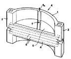
제1도는 본 발명에 관한 흙막이 패널의 일실시예의 사시도.1 is a perspective view of one embodiment of a retaining panel according to the present invention.
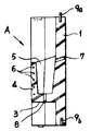
제2도는 제1도의 종단면도.2 is a longitudinal cross-sectional view of FIG.
제3도는 다른 실시예의 종단면도.3 is a longitudinal sectional view of another embodiment.
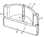
제4도는 다른 실시예의 사시도.4 is a perspective view of another embodiment.
제5도는 제4도의 종단면도.5 is a longitudinal cross-sectional view of FIG.
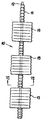
제6도는 앵커의 평면도.6 is a plan view of the anchor.
제7도는 제6도의 Ⅶ-Ⅶ선 단면도.7 is a cross-sectional view taken along
제8도는 시공상태의 사시도.8 is a perspective view of a construction state.
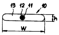
제9도는 종래의 일실시예의 사시도.9 is a perspective view of one conventional embodiment.
제10도는 제9도의 종단면도.10 is a longitudinal sectional view of FIG.
제11도-제13도는 종래기술의 설명도.11-13 are explanatory views of the prior art.
본 발명은 흙막이 패널에 관한 것으로서, 특히 아취형구조의 흙막이 패널에 관한 것이다.BACKGROUND OF THE INVENTION 1. Field of the Invention [0001] The present invention relates to mudguard panels, and more particularly to mudstone panels.
본 발명의 발명자는 아취형구조의 흙막이 패널에 관하여 여러가지의 발명을 개시하고 있다. 발명자는 기히 아취형구조는 터널구조등은 물론, 흙막이 패널에 있어서도 극히 유리하다는 점을 개시한바 있다.The inventor of the present invention discloses various inventions with respect to the jade panel structure. The inventors have disclosed that the arch structure is extremely advantageous not only for tunnel structures but also for earthquake panels.
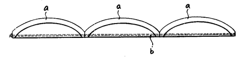
그중에서 발명자는 제9도 내지 제11도에 도시한 바와 같이 원호상의 아취부(a)에 PC 강재(b)를 걸어서 프레스트레스 힘을 집어넣어서 토압에 의한 아취부(a)의 변위를 프레스트레스 힘에 의하여 방지하고, 크랙의 발생을 극렬억제함으로서 큰 토압을 패널에 부담시킬 수 있다.Among them, as shown in Figs. 9 to 11, the inventor puts a prestressing force on the circular arc-shaped abutment (a), injects a prestress force, and presses the displacement of the abutment (a) by earth pressure. A large earth pressure can be imposed on a panel by preventing by a force and suppressing generation of a crack extremely.
이와 같이 프레스트레스 힘을 도입하는 것은 기술적으로 고도할 뿐 아니라 패널제조에 많은 수공이 들어 제조비용이 높아지는 것이다.In this way, the introduction of the press stress force is not only technically high, but also requires a lot of manual work to manufacture the panel, thereby increasing the manufacturing cost.
또 제11도에 도시하는 바와 같이 여러개의 패널에 한줄의 PC 강재를 관통시켜서 일체로 고정하고 전체에 한번 프레스트레스 힘을 주는 발명을 개시하였다. 이와 같은 발명에는 제12도에 도시하는 바와 같이 패널(a)의 상하위치가 다소 일그러졌을때 PC 강재를 통하여 프레스트레스 힘을 주기가 매우 곤란한 문제가 있다. 또 제13도에 도시하는 바와 같이 패널(a)을 곡선상으로 배치하였을때도 같은 문제가 있다.In addition, as shown in FIG. 11, an invention is disclosed in which a single line of PC steel is passed through a plurality of panels to be integrally fixed and give a press stress once to the entire panel. In this invention, as shown in FIG. 12, when the up-and-down position of the panel a is slightly distorted, it is very difficult to give a press stress force through PC steel. As shown in FIG. 13, the same problem occurs when the panel a is arranged in a curved shape.
또한 프레스트레스 힘을 주는것은 극히 고도한 전문기술을 필요로 하여 숙련자가 꼭 요구된다.In addition, applying prestressing force requires extremely high level of expertise and requires skilled personnel.
본 발명에 관한 흙막이 패널은 PC 강재 대신에 철근을 사용하는 것이다.The retaining panel according to the present invention uses reinforcing bars instead of PC steel.
흙막이 패널은 원호상의 아취부, 이 아취부의 내측에 수평저벽, 이 수평저벽에 대하여 직각을 이루는 아취부에 대하여 걸쳐진 보강부를 가진다.The retaining panel has an arcuate arch, a horizontal bottom wall inside the arch portion, and a reinforcement portion that extends over the arch portion perpendicular to the horizontal bottom wall.
즉, 본 발명은 아취부, 저벽, 보강부에 의하여 감싸진 선반부를 형성한다.That is, this invention forms the shelf part enclosed by a jade part, a bottom wall, and a reinforcement part.
보강부에는 아취부에 대하여 여러개의 철근을 배근한다.In the reinforcement part, several reinforcing bars are placed on the pit.
철근은 인장력을 부담하고, 패널의 아취부의 변위를 방지한다. 철근은 배근하는 것만으로 족하고, 고도한 기술도 필요하지 않다.The reinforcing bar bears the tension and prevents displacement of the dent in the panel. Reinforcing bar is enough to reinforce, and does not need advanced skill.
다음에 예시도에 도시한 일실시예에 의하여 본 발명을 상세히 설명한다.Next, the present invention will be described in detail with reference to an embodiment shown in the accompanying drawings.
도면에서 A는 본 발명에 관한 흙막이 패널이고, 1은 원호상의 아취부이다. 아취부(1)의 좌우양단부에는 각주상의 지승부(2), (2)가 형성되어 있다. 아취부(1)의 내측에는 수평저벽(3)이 형성되어 있고, 이 저벽(3)에 대하여 직각을 이루며 아취부(1)에 대하여 걸쳐진 보강부(4)를 가지고 있다.In the figure, A is the earthen board panel which concerns on this invention, 1 is arcuate-shaped part. At each of the left and right ends of the arch portion 1, support
이들의 아취부(1), 저벽(3), 보강부(4)에 의하여 요입된 공간의 선반부(5)가 형성되여 있다.The
상기의 보강부(4)에는 아취부(1)에 대하여 걸쳐지게 여러개의 철근(6)이 상하로 적절한 간격을 두고 수평으로 배근되여 있다. 철근(6)의 좌우양단부는 지승부(2), (2)내에 이르게 직사각형으로 구부려 그 단부가 지승부(2), (2)내에서 물러나지 않게되여 있다. 철근(6)은 단부를 구부리는 대신 닛트등을 부착시켜도 좋다.In the
도면에서 7, 8은 물구멍이다. 또 아취부(1)의 상면의 좌우중간에는 위치마춤부재(9a)가 돌출되고, 하면에는 구멍(9b)이 설치되여 있다.7, 8 in the figure are water holes. Moreover, the positioning member 9a protrudes in the left and right middle of the upper surface of the archival part 1, and the hole 9b is provided in the lower surface.
이상과 같은 구성의 흙막이 패널(A)은 상지에 설치하려면 제6도 및 제7도에 도시하는 바와 같이 앵커(10)를 사용한다. 앵커(10)는 앵커강재(12)를 씨즈(11)내부를 관통시킨 것으로 씨즈(11)는 합성수지제등으로서 폭이 크게된 광폭부(13)를 여러개 가진다. 광폭부(13)의 폭(W)은 그 높이의 3-10배로 되여 있다. 이 씨즈(11)내부에는 크라우딩재를 충진한다.As shown in Figs. 6 and 7, the anchoring panel A having the above structure is installed in the upper limb. The
이 앵커(10)를 성토(15)상에 설치하고, 흙막이 패널(A)를 닛트(14)에 의하여 고정한다. 앵커(10)상에 순차적으로 성토(15)하여 그 위에 앵커(10)를 설치하고 흙막이 패널(A)을 고정하는 식으로 작업을 해나간다(제8도 참조).This
선반부(5)에는 토사를 집어넣고 식수를 할 수도 있어 외관을 좋게하여 환경미를 도모할 수가 있다.Soil can be put into the
토압이 패널(A)에 작용한때 좌우단을 앵커(10)에 의하여 고정하고 있기 때문에 아취부(1)를 좌우로 펼치려는 힘이 작용하는 것으로 된다. 이 힘은 아취부(1)의 콘크리트에 대하여 인장력으로 작용하나 철근이 배근된 보강부(4)가 존재하기 때문에 철근(6)이 인장력을 부담하여 아취부(1)의 수평변위를 방지한다. 따라서 흙막이 패널(A)의 강도는 향상하여 크랙이 생기지 않게 된다.When the earth pressure acts on the panel A, since the left and right ends are fixed by the
이와 같이 철근(6)이 배근된 보강재(4)를 가지기 때문에 패널(A)에 작용하는 인장력을 철근(6)이 부담하여 강도가 큰 내구성이 높은 패널(A)로서 사용할 수 있을뿐만아니라, 미관이 좋은 패널(A)로서 사용할 수도 있다.Since the reinforcing
제3도에 도시하는 것은 보강부(4)를 저벽(3)의 상하에 크게 형성한 때의 예이다. 제4도 및 제5도에 도시하는 것은 선반부(5)를 흙막이 패널(A)의 하단에 형성한 때의 예이다.Shown in FIG. 3 is an example when the
본 발명은 이상 설명된 바와 같은 구성을 가지고 다음에서와 같은 효과를 얻을수 있다.The present invention has the configuration as described above and can achieve the following effects.
(가) 원호상의 아취부를 가지며 이 아취부의 아취효과에 의하여 토압을 받기때문에 내력이 큰 흙막이 패널이 된다. 실험에서는 종래에 후랫트한 패널에 비하여 동일한 콘크리트 사용체적으로 5배이상, 조건에 따라서는 10배이상의 내력이 생기는 것을 알았다.(A) It has an arc-shaped dent and receives earth pressure by the odor effect of this dent, so it has a large load bearing panel. In the experiment, it was found that the yield strength of 5 times or more, and 10 times or more depending on the conditions of the same concrete use volume as compared with conventional panels.
(나) 후랫트한 패널에 비하여 콘크리트의 사용량을 적게하고, 중량을 최소화할 수 있기때문에 운반이나 시공이 극히 용이하다.(B) It is very easy to transport or construct because it can use less concrete and minimize the weight of the panels compared to the panels.
(다) 철근을 배근한 보강부재를 가지기 때문에 아취부에 작용하는 인장력을 철근이 부담하여 패털의 수평변위를 방지하고, 강도가 큰 내구성이 높은 패널이 된다. 이것은 별표-1에 나타낸 바와 같이 PC 강재를 사용하여 프레스트레스 힘을 준때와 변함이 없는 내구성을 얻을 수 있다.(C) Because it has reinforcing members that are reinforced with rebar, the reinforcing bar bears the tensile force acting on the abutment to prevent horizontal displacement of the panel, resulting in a durable panel with high strength. As shown in Table 1, it is possible to obtain durability which is the same as when pressing stress is applied using PC steel.
(라) 철근을 배근하는 것만으로, 프레스트레스 힘을 주는 것과 같은 고도한 기술을 사용하지 않은 것이어서, 그 제조원가를 싸게한다.(D) Only by reinforcing steel bars, they do not use advanced techniques such as applying prestressing force, thereby lowering the manufacturing cost.
(마) 현장에서도 프레스트레스 힘을 줄 필요가 없어 시공이 용이할 뿐만아니라 숙련작업자를 필요로 하지 않는다.(E) It is not necessary to apply press stress force in the field, so it is easy to install and does not require skilled workers.
(바) 선반부에 토사를 집어넣고 식수를 할수있기 때문에 외관을 좋게 할수 있어 환경미화를 도모할수 있다. 또 크랙이 쉽게 발생하지 않기때문에 패널표면이 오손되지 않아 미관을 장구하게 유지할 수 있다.(F) Because soil can be put into the shelf and drinking water, the appearance can be improved and the environment can be enhanced. In addition, since cracks do not easily occur, the surface of the panel is not contaminated so that the appearance can be kept long.
(사) 토하중이 커지는 것에 따라 특히 패널의 두께를 바꾸지 않고, 다소의 콘크리트 강도를 높여주는 것과 보강철근의 개수나 크기를 증가시키는 것만으로서 패널의 내력을 향상시킬 수 있는 것이어서, 거푸집을 바꿀 필요가 없어 경제성이 높은 패널을 제공할 수 있다.(G) As the load increases, it is necessary to change the formwork by increasing the concrete strength and increasing the number and size of reinforcing bars without increasing the thickness of the panel. There is no economical panel can be provided.
[표 -1]TABLE -1

Claims (1)
Applications Claiming Priority (3)
| Application Number | Priority Date | Filing Date | Title |
|---|---|---|---|
| JP27967 | 1987-02-09 | ||
| JP?62-27967 | 1987-02-09 | ||
| JP62027967A JPS63197721A (en) | 1987-02-09 | 1987-02-09 | Sheathing panel |
Publications (2)
| Publication Number | Publication Date |
|---|---|
| KR880010201A KR880010201A (en) | 1988-10-07 |
| KR910002890B1 true KR910002890B1 (en) | 1991-05-09 |
Family
ID=12235660
Family Applications (1)
| Application Number | Title | Priority Date | Filing Date |
|---|---|---|---|
| KR1019870012725A KR910002890B1 (en) | 1987-02-09 | 1987-11-12 | Retaining panel |
Country Status (4)
| Country | Link |
|---|---|
| EP (1) | EP0278145A1 (en) |
| JP (1) | JPS63197721A (en) |
| KR (1) | KR910002890B1 (en) |
| AU (1) | AU591024B2 (en) |
Cited By (1)
| Publication number | Priority date | Publication date | Assignee | Title |
|---|---|---|---|---|
| KR100748550B1 (en) * | 2004-08-26 | 2007-08-10 | 조수원 | The embeded plate |
Families Citing this family (6)
| Publication number | Priority date | Publication date | Assignee | Title |
|---|---|---|---|---|
| AU629352B2 (en) * | 1989-07-06 | 1992-10-01 | Derek John Olsen | Building block |
| AU667458B2 (en) * | 1990-09-17 | 1996-03-28 | Andrew Reid Nominees Pty. Ltd. | Retaining wall |
| CZ11848U1 (en) * | 2001-03-29 | 2002-01-07 | Alojz Ing. Hanuliak | Part of high-pressure barrier and the high-pressure barrier per se |
| UA74260C2 (en) * | 2001-04-25 | 2005-11-15 | Алєксандр Алєксєєвіч Фомєнков | Sheet pile (versions) and method to make it (versions) |
| CN105862912B (en) * | 2016-04-18 | 2018-01-09 | 中冶建工集团有限公司 | A kind of agent on crack resistance of concrete sliding pile panelling construction method |
| CN117306565B (en) * | 2023-11-28 | 2024-03-29 | 广州番禺职业技术学院 | Slope support device and method |
Family Cites Families (3)
| Publication number | Priority date | Publication date | Assignee | Title |
|---|---|---|---|---|
| US3922864A (en) * | 1974-02-25 | 1975-12-02 | Hilfiker Pipe Co | Stringer for retaining wall construction |
| GB2157737A (en) * | 1984-04-19 | 1985-10-30 | Audrey Jane Ryder | Bricks and plant holder |
| JPS61266735A (en) * | 1985-05-17 | 1986-11-26 | Kensetsu Kiso Eng Kk | Sheathing panel |
-
1987
- 1987-02-09 JP JP62027967A patent/JPS63197721A/en active Granted
- 1987-03-18 EP EP87302333A patent/EP0278145A1/en not_active Withdrawn
- 1987-11-12 KR KR1019870012725A patent/KR910002890B1/en not_active IP Right Cessation
-
1988
- 1988-02-03 AU AU11248/88A patent/AU591024B2/en not_active Ceased
Cited By (1)
| Publication number | Priority date | Publication date | Assignee | Title |
|---|---|---|---|---|
| KR100748550B1 (en) * | 2004-08-26 | 2007-08-10 | 조수원 | The embeded plate |
Also Published As
| Publication number | Publication date |
|---|---|
| KR880010201A (en) | 1988-10-07 |
| EP0278145A1 (en) | 1988-08-17 |
| AU1124888A (en) | 1988-08-11 |
| JPH0453203B2 (en) | 1992-08-26 |
| AU591024B2 (en) | 1989-11-23 |
| JPS63197721A (en) | 1988-08-16 |
Similar Documents
| Publication | Publication Date | Title |
|---|---|---|
| US4470728A (en) | Reinforced earth structures and facing units therefor | |
| US4592678A (en) | Modular block retaining wall | |
| US3316721A (en) | Tensioned retaining wall for embankment | |
| DE2521777C2 (en) | Prefabricated wall panel made of reinforced concrete for the production of a retaining wall or the like. | |
| KR910002890B1 (en) | Retaining panel | |
| EP1426521B1 (en) | Facade for walls | |
| NO115718B (en) | ||
| NZ226940A (en) | Facings for reinforced earth construction | |
| DE2117711A1 (en) | Foundation stand that can be placed on the ground | |
| KR100397768B1 (en) | Substructure construction device of green house | |
| JPH0971956A (en) | Earth-retaining wall | |
| DE2201138A1 (en) | Concrete floor | |
| US2116335A (en) | Wrapping for structural shapes | |
| DE20022421U1 (en) | Structural steel construction, concrete slab element and concrete ceiling or concrete floor with integrated heating or cooling function | |
| JP2509162B2 (en) | Slope stable structure as in-plane structure | |
| DE2747774C3 (en) | Holding device for support cheeks to support slope material on an embankment | |
| DE853954C (en) | Ceiling with multitudes of intersecting ceiling beams | |
| CN213014662U (en) | Waterproof steel structure for reinforcing foundation | |
| CN217557771U (en) | Post-cast storehouse post wall of filling prevents structure that ftractures | |
| KR20200006329A (en) | Reinforcing structure of block type retaining wall and construction method thereof | |
| JP6823850B2 (en) | Retaining structure | |
| DE3931316C2 (en) | Process for producing a shoring or retaining wall for terrain cuts | |
| AU743289B2 (en) | Building block | |
| JPS6043495B2 (en) | How to build a retaining wall | |
| JPH022770Y2 (en) |
Legal Events
| Date | Code | Title | Description |
|---|---|---|---|
| A201 | Request for examination | ||
| G160 | Decision to publish patent application | ||
| E701 | Decision to grant or registration of patent right | ||
| GRNT | Written decision to grant | ||
| FPAY | Annual fee payment |
Payment date: 20010502 Year of fee payment: 11 |
|
| LAPS | Lapse due to unpaid annual fee |