KR910002068B1 - Method for controlling to keep off detects on magnetic disks - Google Patents
Method for controlling to keep off detects on magnetic disks Download PDFInfo
- Publication number
- KR910002068B1 KR910002068B1 KR1019870012584A KR870012584A KR910002068B1 KR 910002068 B1 KR910002068 B1 KR 910002068B1 KR 1019870012584 A KR1019870012584 A KR 1019870012584A KR 870012584 A KR870012584 A KR 870012584A KR 910002068 B1 KR910002068 B1 KR 910002068B1
- Authority
- KR
- South Korea
- Prior art keywords
- track
- defect
- record
- tracks
- defects
- Prior art date
Links
Images


Classifications
-
- G—PHYSICS
- G11—INFORMATION STORAGE
- G11B—INFORMATION STORAGE BASED ON RELATIVE MOVEMENT BETWEEN RECORD CARRIER AND TRANSDUCER
- G11B20/00—Signal processing not specific to the method of recording or reproducing; Circuits therefor
- G11B20/10—Digital recording or reproducing
- G11B20/18—Error detection or correction; Testing, e.g. of drop-outs
- G11B20/1883—Methods for assignment of alternate areas for defective areas
-
- G—PHYSICS
- G11—INFORMATION STORAGE
- G11B—INFORMATION STORAGE BASED ON RELATIVE MOVEMENT BETWEEN RECORD CARRIER AND TRANSDUCER
- G11B20/00—Signal processing not specific to the method of recording or reproducing; Circuits therefor
- G11B20/10—Digital recording or reproducing
- G11B20/12—Formatting, e.g. arrangement of data block or words on the record carriers
- G11B20/1217—Formatting, e.g. arrangement of data block or words on the record carriers on discs
- G11B20/1252—Formatting, e.g. arrangement of data block or words on the record carriers on discs for discontinuous data, e.g. digital information signals, computer programme data
-
- G—PHYSICS
- G11—INFORMATION STORAGE
- G11B—INFORMATION STORAGE BASED ON RELATIVE MOVEMENT BETWEEN RECORD CARRIER AND TRANSDUCER
- G11B2220/00—Record carriers by type
- G11B2220/20—Disc-shaped record carriers
-
- G—PHYSICS
- G11—INFORMATION STORAGE
- G11B—INFORMATION STORAGE BASED ON RELATIVE MOVEMENT BETWEEN RECORD CARRIER AND TRANSDUCER
- G11B2220/00—Record carriers by type
- G11B2220/20—Disc-shaped record carriers
- G11B2220/25—Disc-shaped record carriers characterised in that the disc is based on a specific recording technology
- G11B2220/2508—Magnetic discs
Abstract
내용 없음No content
Description
제1도(a)는 자기디스크의 트랙에 결함이 없는 경우의 1실린더내의 2트랙의 각 레코드각의 위치관계를 도시한 도면.Fig. 1 (a) is a diagram showing the positional relationship of each record angle of two tracks in one cylinder when there is no defect in the track of the magnetic disk. Fig.
제1도(b)는 1트랙에 결함이 있는 경우의 1실린더내의 2트랙의 각 레코드간의 위치관계를 도시한 도면.FIG. 1 (b) is a diagram showing a positional relationship between respective records of two tracks in one cylinder when there is a defect in one track; FIG.
제2도는 자기디스크의 3개 트랙의 각 결함위치를 표시한 예를 도시한 도면.FIG. 2 is a diagram showing an example in which each defect position of three tracks of the magnetic disk is displayed; FIG.
제3도는 본원 발명에 의한 1실린더내의 전체 트랙의 결함위치정보를 각 트랙에 기록한 예를 도시한 도면.FIG. 3 is a diagram showing an example in which defect position information of all the tracks in one cylinder according to the present invention is recorded in each track; FIG.
제4도는 제3도에 도시한 결함위치정보에 의하여 트랙에 레코드를 기록한 예를 도시한 도면.FIG. 4 is a diagram showing an example of recording a record on a track by defect position information shown in FIG. 3;
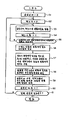
제5도는 본원 발명에 의하여 1실린더내의 전체 트랙의 동일한 결함위치 정보등록을 실시하는 경우의 등록처리예의 플로챠트.FIG. 5 is a flowchart of a registration processing example in the case where the same defect position information registration of all tracks in one cylinder is performed according to the present invention. FIG.
제6도는 본원 발명에 의한 자기디스크의 결함회피 제어방법의 일실시예를 도시한 도면.FIG. 6 is a view showing an embodiment of a defect avoidance control method of a magnetic disk according to the present invention; FIG.
본원 발명은 자기디스크의 결함회피 제어방법에 관한 것이며, 특히 디스크액세스법으로서, 복수개의 CCW(channel command word)로 이루어진 채널프로그램으로 북수의 트랙을 효율적으로 액세스하는 경우, 트랙상에 결함이 있는데도 불구하고, 고속으로 트랙에 데이터를 기입 또는 데이터를 해독함으로써 데이터프로세서를 고(高) 스루풋(throughput)으로 데이터 전송하는 것이 가능한 자기디스크의 결함회피 제어방법에 관한 것이다.The present invention relates to a defect avoidance control method for a magnetic disk, and more particularly, as a disk access method, in the case of efficiently accessing a track number in a channel program composed of a plurality of channel command words (CCW) And to a method of controlling a defect of a magnetic disk capable of data transfer at a high throughput by writing data to the track at a high speed or decrypting the data at high speed.
종래의 자기디스크장치에 있어서는, 예를들면 일본국 특허출원공개 제1974-52612호 공보에 기재되어 있는 바와같이, 자기디스크의 각 트랙에는 통상 최초의 에리어에 그 트랙내의 결함위치정보가 기록되어 있다. 결함이 존재하는 경우에는, 결함부를 포함하는 일정한 길이를 가진 에리어를 비월(飛越)하여 레코드를 형성함으로써, 결함회피를 행하고 있다.In the conventional magnetic disk apparatus, as described in, for example, Japanese Patent Application Laid-Open No. 1974-52612, defect track position information in the track is recorded in each track of the magnetic disk in the first area . When a defect exists, defects are avoided by forming a record by interlacing an area having a predetermined length including the defect part.
그런데, 디스크액세스법으로서, 복수개의 CCW로 이루어진 채널프로그램에 의해 복수의 트랙중 1트랙을 다른 트랙으로 전환하여, 좋은 효율로 액세스하는 방법이 있다. 이 경우, 각 트랙에는 다른 트랙으로 전환 이동하기 위한 시간만큼, 더미레코드가 설치되어 있으며, 그 더미레코드의 위치에서 다른 트랙으로 전환을 행한다. 이 더미레코드는 정보가 기록되어 있지 않은 전혀 쓸모없는 에리어이기 때문에, 더미레코드의 길이를 될 수 있는 한 적게 하는 것이 바람직하다. 따라서, 더미레코드의 길이는 정확하게 전환시간에 일치시켜서 설치되어 있으며, 전혀 여유가 없다.As a disk access method, there is a method in which one track out of a plurality of tracks is switched to another track by a channel program made up of a plurality of CCWs and accessed with good efficiency. In this case, each track is provided with a dummy record for a time for switching to another track, and switching from the position of the dummy record to another track is performed. Since this dummy record is a completely useless area in which information is not recorded, it is desirable to reduce the length of the dummy record as much as possible. Therefore, the length of the dummy record is set to match the conversion time precisely, and there is no room at all.
실린더상의 각 트랙에 결함이 없고 각 트랙의 레코드위치가 전체 트랙에 대하여 일치되어 있는 경우에는, 어떤 트랙에 있어서의 하나의 레코드의 액세스 종료후에 다른 트랙의 다음의 레코드로 트랙전환에 의해 액세스하는 경우에, 이들 양 레코드간에 트랙원주방향으로 보아서, 전환소요시간을 발생시키는 간격이 있으므로, 지장없이 트랙전환을 행할 수 있다. 그러나, 트랙에 결함이 있고 결함회피를 위해 레코드를 분리하거나 또는 그 위치를 비키어서 레코드 위치를 변경한 경우에는 예를들면 위치가 정상위치로부터 바뀐 레코드와 다른 트랙상의 정상위치에 있는 레코드를 트랙을 전환하여 연속적으로 액세스하려고 하는 경우에 각 레코드간의 트랙원주방향으로 본 거리가 상기 레코드위치변위에 의하여 짧아져 있으며, 트랙전환 소요시간을 발생시킬 수 없는 경우에 발생한다. 이와 같은 위치관계에 있는 각 레코드를 트랙을 전환하여 액세스하는 경우에는 레코드 간격이 트랙 전환시간에 충분하지 않기 때문에, 트랙전환 직후에는 결함이 없는 트랙의 다음 레코드의 선두에서 액세스할 수 없고, 결함이 없는 트랙을 갖는 자기디스크의 1회전하는 것을 기다려서 이 레코드를 그 선두의 위치에서 액세스하게 되어, 액세스 시간이 길어지는 문제가 있다.In the case where there is no defect in each track on the cylinder and the record position of each track is matched with respect to all the tracks, when the access to one record in a certain track is to be accessed by track switching to the next record after another track , There is a gap between these two records in the circumferential direction of the track to generate the required switching time, so that the track can be switched without any trouble. However, if there is a defect in the track and the record position is changed by separating or shifting the record to avoid the defect, for example, if the position is changed from the normal position and the record in the normal position on the other track The track distance in the track circumferential direction between each record is shortened due to the record position displacement and the track switching time can not be generated. If each record in such a positional relationship is accessed by switching the track, since the record interval is not sufficient for the track switch time, the track can not be accessed immediately from the beginning of the next record of the track without a defect, There is a problem in that the access to the record is waited for by one rotation of the magnetic disk having the missing track and the record is accessed at the leading position, thereby increasing the access time.
본원 발명의 목적은 종래 기술의 문제점을 해결하여 고속으로 트랙에 데이터를 기입 또는 데이터를 해독함으로써 데이터 프로세서를 고스루풋으로 데이터 전송을 할 수 있는 자기디스크의 결함회피 제어방법을 제공하는 것이다.SUMMARY OF THE INVENTION It is an object of the present invention to provide a defect avoidance control method for a magnetic disk capable of solving the problems of the prior art and capable of transferring data to a data processor with high throughput by writing data in a track at high speed or decrypting data.
본원 발명에 있어서는 자기디스크 장치에 있어서의 각 실린더상의 각 트랙에 이 실리더 상의 각 트랙의 결함의 위치정보를 전체 트랙에 대해 모은 것을 결함위치 정보로서 등록한다. 즉 1실린더 상의 어느 한 트랙에 결함이 있는 경우에, 이 결함위치에 대응하는 다른 모든 트랙상의 위치에 결함이 있다고 간주하여, 각 트랙에 결함위치 정보등록을 행한다. 이에 따라서 전체 트랙에 동일한 결함위치 정보가 등록된다.In the present invention, the position information of the defects of each track on the cylinder is collected for each of the tracks on each cylinder in the magnetic disk device as defective position information. In other words, when any one track on one cylinder has a defect, it is considered that there is a defect in the position on all other tracks corresponding to this defect position, and defect position information is registered in each track. Accordingly, the same defect position information is registered in all the tracks.
종래 기술에 있어서, 자기디스크의 각 트랙에 결함위치정보를 등록하여, 레코드의 액세스시에는 이 정보에 의거하여 결함회피하는 것이 이루어지고 있다. 본원 발명에 있어서는 상기와 같이, 1실린더상의 전체 트랙에 대해 동일하게 등록된 결함위치정보에 의거하여, 종래 기술에 따른 결함회피 동작을 레코드의 해독기입 액세스시에 행한다. 따라서 각 트랙에 동일 길이나 형식의 복수의 레코드를 기록한 경우에는 각 트랙상의 각 레코드의 트랙선두로부터의 거리가 다른 모든 트랙에 있어서의 대응 레코드의 트랙선두로부터의 거리와 같아진다. 즉 각 트랙상의 레코드는 트랙전환 시간에 대응하는 거리만큼 소정의 레코드간의 간격을 유지하면서 전 트랙에 대하여 정렬하며, 전체 트랙에 동일한 레코드 포맷으로 레코드가 기록된다. 따러서 레코드 해독기입 액세스에 있어서 트랙전환을 한 경우에, 트랙전환 직후에 레코드를 디스크의 회전을 기다리지 않고 액세스하는 것이 가능해진다. 이에 따라서, 데이터처리장치에서는 트랙상의 결함을 의식하지 않고 고속으로 데이터전송을 행할 수 있게 된다.In the conventional technique, defect position information is registered in each track of a magnetic disk and defects are avoided based on this information when a record is accessed. In the present invention, as described above, the defect avoiding operation according to the conventional technique is performed at the time of decode-write access of the record, based on the defect position information similarly registered for all the tracks in one cylinder. Therefore, when a plurality of records of the same length or type are recorded on each track, the distance from the track head of each record on each track is equal to the distance from the track head of the corresponding record in all other tracks. That is, the records on each track are arranged with respect to all the tracks while maintaining the interval between predetermined records by a distance corresponding to the track switching time, and records are recorded in the same record format in all tracks. It is possible to access the record immediately after switching the track without waiting for the rotation of the disk. As a result, the data processing apparatus can perform data transfer at high speed without being aware of defects on the track.
본원 발명에 의하면, 동일한 회전축을 가진 복수개의 자기디스크 상에 결함이 존재하는 경우에도, 1실린더내의 각 트랙상의 각 레코드의 상대위치를 동일하게 하는 것이 가능해지므로, 복수개의 CCW 체인을 가진 채널프로그램에 의해 복수의 트랙을 효율적으로 액세스하려고 하는 경우, 디스크회전을 기다리지 않고도 결함을 의식하지 않고 작성된 자기디스크 액세스용 프로그램을 결함을 가진 자기디스크에도 적용할 수 있으므로, 결함에 의한 자기디스크장치의 성능의 저하를 야기하지 않아도 된다.According to the present invention, even when a defect exists on a plurality of magnetic disks having the same rotation axis, the relative positions of the respective records on each track in one cylinder can be made the same, so that a channel program having a plurality of CCW chains It is possible to apply the program for magnetic disk access which is created without being conscious of the defect to the magnetic disk having the defect without waiting for the disk rotation and thus the performance of the magnetic disk apparatus due to the defect is deteriorated .
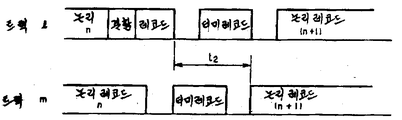
본원 발명을 설명하기 앞서 종래 기술의 문제점을 설명한다. 제1도(a)는 1실린더내의 결함이 없는 2개의 자기디스크 트랙에 레코드가 기록된 상태를 도시하며, 제1도(b)는 결함이 있는 트랙에 결함을 피해서 레코드가 기록된 상태를 도시한다.Prior to describing the present invention, the problems of the prior art will be described. FIG. 1 (a) shows a state in which a record is recorded on two magnetic disk tracks without defects in one cylinder. FIG. 1 (b) shows a state in which a record is recorded so as to avoid defects in a defective track do.
제1도(a)에 도시한 바와같이, 결함이 없는 상태에서는 각 트랙마다 더미레코드의 위치가 일정하기 때문에 트랙의 전환동작에 아무런 문제는 없으나, 제1도(b)에 도시한 바와같이, 임의의 트랙에 결함이 있는 상태에서는 결함위치를 건너뛰어 결함트랙에 레코드가 기록되어 있기 때문에(여기서 레코드 n이 결함을 회피하기 위해 둘로 분리되어 있음), 다른 트랙과의 더미레코드의 위치 어긋남이 발생하여, 전환에 시간이 걸린다. 즉 제1도(a), (b)의 예에서는 각 트랙에 일정길이의 복수개의 논리레코드와, 각 인접논리 레코드간에 더미레코드가 존재하고 있다. 1실린더내의 트랙 1 및 m이 결함이 없는 상태에서는 제1도(a)에 도시된 바와같이, 트랙 1의 논리레코드 n을 액세스한 후, 다음에 동일 실린더내의 다른 트랙 m의 논리레코드(n+1)을 액세스하면, 더미레코드 길이를 기입/독해 헤드의 둘중에서 하나를 다른 헤드로 전기적 헤드 전환하는데 소요되는 시간에 적절하게 일치시키고 있어도, 전환 전과 후의 더미레코드의 위치가 2개 트랙의 정상위치에 합치되어 있기 때문에 트랙 m의 논리레코드(n+1)은 전환 직후에 액세스 하게 된다. 그리하여 트랙 m의 놀리레코드(n+1)에 액세스될때 자기디스크가 1회전하는 동안 디스크으 ㅣ회전대기없이 목적한 레코드를 액세스할 수 있다. 그러나 제1도(b)에 도시된 바와같이, 어떤 트랙의 레코드 n 이전에 트랙1에 결함이 존재하는 경우, 더미레코드길이가 기입/해독헤드의 둘중에서 하나를 다른 헤드로 전기적 헤드전환하는데 소요되는 시간에 일치시키고 있을때는, 결함이 없는 다른 트랙 m의 레코드(n+1)에의 액세스는 1회전 대기로 되고, 액세스시간의 대표적인 증가로 되어 버린다.As shown in Fig. 1 (a), there is no problem in the track switching operation because the position of the dummy record is constant for each track in the absence of a defect. However, as shown in Fig. 1 (b) In a state in which there is a defect in an arbitrary track, since a record is recorded in the defect track by skipping the defect position (here, the record n is divided into two in order to avoid defects), the positional deviation of the dummy record with another track occurs So that it takes time to switch. That is, in the examples of FIGS. 1 (a) and 1 (b), there are a plurality of logical records each having a predetermined length in each track and a dummy record between adjacent logical records. In a state in which there is no defect in the
즉 제1도(a)에 도시한 바와같이, 더미레코드의 위치가 트랙 1과 m의 정상위치에 있는 경우에는 헤드전환에 소요되는 시간 t1만큼 경과하면, 다른 헤드는 전환 전의 트랙 m의 논리레코드(n+1)의 직전에 도달하므로, 그대로 레코드(n+1)의 정보를 독해할 수 있다. 그러나 제1도(b)에 도시된 바와같이, 트랙 1의 더미레코드의 위치가 트랙 m의 대응하는 더미레코드위치로부터 어긋나 있는 경우에는, 전환 전의 트랙 1의 레코드 n의 후미와 전환 후의 트랙 m의 레코드 (n+1)의 선두 사이의 시간 t2가 헤드전환에 소요되는 시간 t1보다 짧기 때문에, 전환시간 t1이 경과하면, 트랙의 기입/해독헤드는 전환 전 트랙의 논리레코드(n+1)의 중도까지 나아가 있게 되어, 1회전 후의 선두 위치까지 대기하지 않으면 안된다.That is, as shown in FIG. 1 (a), when the position of the dummy record is at the normal position of the
이와 같이, 종래의 기술에서는 1트랙내의 결함회피만을 목적으로 하고 있기 때문에, 트랙전환에 있어서 결함을 회피하는 것으로 인한 기록레코드의 위치어긋남의 영향을 전혀 고려하지 않고 있었다.As described above, since the prior art aims only to avoid defects in one track, no consideration is given to the influence of the positional shift of the record record due to the avoidance of defects in track switching.
본원 발명은 이와 같은 종래 기술의 문제점을 해결하고, 자기 디스크 트랙상에서 결함으로 레코드위치가 어긋난 경우에도, 레코드 액세스시의 트랙전환에 있어서 자기디스크의 회전을 대기하지 않고, 레코드 액세스를 행할 수 있도록 한 것이며, 다음에 본원 발명의 원리 및 실시예에 대하여 설명한다.It is an object of the present invention to solve the problems of the related art as described above and to provide a recording apparatus capable of performing record access without waiting for rotation of the magnetic disk in switching a track at the time of record access even when the record position is shifted due to a defect on the magnetic disk track Next, the principles and embodiments of the present invention will be described.
제2도는 자기디스크의 1실린더가 3트랙이라고 가정한 경우의 각 트랙의 결함위치를 나타낸 도면이다. 트랙 1에는 결함(21), (22)가, 트랙 2에 결함(23)이, 트랙 3에는 결함(24), (25)가 각기 존재한다. 이 경우에 본원 발명에서는, 결함위치정보로서 각 트랙의 선두로부터 결함위치의 거리를 SD11, SD12, SD21, SD31, SD32로 표시한다. 통상, 각 트랙의 결함등록은 미리 정해진 m개의 에리어가 준비되며, 결함이 m개 보다 적을때는 예비에리어로서 후에 결함이 생겼을때에 추가할 수 있는 포맷으로 되어 있다. 예를들면, 홈어드레스는 7개의 결함에리어가 준비되어 있으나, 실제로는 평균 1-2개의 결함 밖에 없기 때문에, 남은 에리어를 본원 발명을 위한 공통 결함위치정보를 기록하는데 이용한다.FIG. 2 is a view showing the position of defects of each track when it is assumed that one cylinder of the magnetic disk is three tracks.
제3도는 트랙 n에 등록하는 결함위치정보 및 의사결함 플랙(flag)을 도시한 도면이다.FIG. 3 is a diagram showing defect position information and a pseudo defect flag registered in the track n. FIG.
통상, 가변길이 레코드의 트랙형식은 제3도에 도시된 바와같이, 홈어드레스(31)와 레코드(32), (33), (34)등 복수의 레코드로 구성되며, 홈어드레스(31)내에는 (41)로 표시한 바와같이 결함위치정보가 등록되어 있다. 제3도에서는 이 결함위치정보(41)는 1실린더내의 전체 트랙의 복수개의 결함위치정보 SDn을 작은 것에서 큰 것의 순서로 배열하고, 각 결함위치정보는 이 정보와 홈어스레스에 의해 표시되는 결함이 다시 각 트랙 대응으로 해당 트랙의 결함인지 여부를 표시하는 의사결함플랙(42)를 포함한다. 즉 제3도에 도시된 바와같이, 1실린더가 3트랙이고 5개의 결함이 존재하는 경우, 각 3개의 트랙의 홈어드레스(31)에 거리가 작은 것으로부터 차례로 5개의 결함정보, SD11, SD31, SD21, SD32, SD12를 기록하고, 나머지 2개의 예비 에리어로 한다. 그리고 각 결함위치정보에는 의사플랙(42)와 결함위치(43)가 기록된다. 의사플랙(42)는 해당하는 결함이 자신의 트랙일때는 “1”, 다른 트랙일때는 “0”을 기입한다.Typically, the track format of the variable length record is composed of a plurality of records such as a
1실린더내의 전체 트랙의 결함의 총수가 많아지고, 각 트랙의 홈어드레스에 전체 트랙의 결함의 위치정보를 등록할 수 없게 된 경우에, 각 트랙에서는 의사플랙(42)의 정보를 사용하여 홈어드레스(31)를 가진 트랙에 존재하는 결함위치정보만이 홈어드레스에 남도록 자신의 트랙의 결함위치정보만을 선택하여, 이것을 결함위치정보로 한다. 즉 종래의 결함회피를 행한다. 통상은 결함수가 1실린더내의 트랙에 이와 같이 많아지는 일은 없다.When the total number of defects of all the tracks in one cylinder becomes large and the positional information of the defects of all the tracks can not be registered in the home address of each track, Only the defective position information of the track of its own is left so that only the defective position information in the track having the
제4도는 결함위치정보에 의거하여, 레코드를 기록한 일례를 도시한 도면이고, 제5도는 본원 발명에 의해 홈어드레스에 결함위치정보의 등록을 실시하는 경우의 등록처리의 플로차트이다.FIG. 4 is a view showing an example of recording a record on the basis of defect position information, and FIG. 5 is a flowchart of registration processing when defect position information is registered in a home address according to the present invention.
결함위치정보는 통상 자기디스크원판 제조공정 후의 하드이니셔라이즈(initialize)시 및 계산기 시스템조립 후의 소프트이니셔라이즈시에, 각기 이니셔라이즈용 처리장치 또는 계산기 시스템에 의하여 홈어드레스 등록된다.The defect location information is registered in the home address by the initialization processing device or the computer system, respectively, at the time of hard initialization after the magnetic disk original plate manufacturing process and at the time of soft initialization after the computer system is assembled.
제5도를 참조하면, 우선 초기설정으로서 실린더 m와 헤드 n를 제로로 한다(스텝 51, 52). 다음에 헤드를 실린더 m, 헤드 n에 위치 부여하고, 하드이니셔라이즈 및 소프트이니셔라이즈와 동시에, 종래와 같은 방법으로 목적 트랙상의 결함을 검출하여, 해당 트랙의 선두로부터의 거리를 각기 구한다(스텝 53). 헤드 n을 +1하여 (스텝 54), 해당 실린더 m의 최후의 트랙까지 결함위치 검출동작을 반복한다(스텝 53-55). 실린더 m으로부터 얻은 결함위치정보에 의해 각 헤드의 결함위치 정보테이블을 작성한다(스텝 56). 복수개의 결함위치정보를 결함위치의 작은 값 순으로 배열하고, 이것을 해당 실린더 m내의 전체 트랙 공통의 결함위치정보로 한다(스텝 57). 또한 각 검출된 결함이 플랙을 가진 트랙에 존재하는지 여부를 나타내도록 각 트랙 대응으로 각 결함위치정보에 의사결함플랙을 설정한다. (스텝 58). 실린더 m내의 전체 트랙에 결함플랙과 공통의 결함위치정보를 등록한다.(스텝 59). 실린더 m을 +1하고(스텝 60), 이 동작을 반복함으로써 전체 실린더에 대하여 결함정보의 등록을 한다(스텝 61).Referring to FIG. 5, firstly, cylinder m and head n are set to zero as initial settings (steps 51 and 52). Next, the head is placed on the cylinder m and the head n, and defects on the target track are detected in the same manner as in the conventional method at the same time as the hard initialization and soft initialization, and distances from the head of the track are obtained Step 53). The head n is incremented by 1 (step 54), and the defective position detection operation is repeated up to the last track of the cylinder m (step 53-55). And the defect position information table of each head is created based on the defect position information obtained from the cylinder m (step 56). A plurality of pieces of defect position information are arranged in the order of small values of the defect positions, and this is used as defect position information common to all the tracks in the cylinder m (step 57). Also, a pseudo defect flag is set in each defect position information in correspondence with each track so as to indicate whether or not each detected defect exists in a track having a flag. (Step 58). The defect flag and the common defect position information are registered in all the tracks in the cylinder m (step 59). The cylinder m is incremented by 1 (step 60), and this operation is repeated to register the defect information for all the cylinders (step 61).
제4도는 제2도의 예에 나타낸 결함위치정보가 트랙 n의 홈어드레스(31)에 이미 등록되어 있는 상태에서, 다시 트랙 n의 레코드(33), (34), (35)를 기록했을때의 트랙형식을 나타낸다. 레코드(32)는 통상의 데이터기록 이외의 특별한 정보를 포함한다. 상술한 바와같이 본원 발명에 의하면 1실린더내의 전체 트랙에 대하여 동일결함 위치정보를 등록하므로, 각 트랙에 같은 길이의 복수개의 레코드를 기록하면, 각 트랙의 레코드 n의 트랙선두로부터의 거리는 동일하게 된다.4 shows the case where the defect position information shown in the example of FIG. 2 is already registered in the
제6도는 본원 발명의 1실시예를 도시한 각 자기디스크의 결함회피제어 기록방법을 설명한 도면이다. 제6도(a)는 결함이 없는 상태의 트랙상의 각 레코드의 배치도, 제6도(b)는 종래의 각 트랙상의 결함회피에 의한 결함트랙상의 레코드의 배치도, 제6도(c)는 본원 발명에 의한 결함회피를 행한 각 결함트랙상의 레코드의 배치도이다. 제6도의 (b)와 (c)는 (a)의 레코드배치와 대비하여, 등록된 결함위치정보에 의거하여 결함을 회피하도록 레코드 위치를 분리하거나 또는 비키어서 레코드기록을 한 경우의 레코드 배치를 도시한다. (b)에는 결함을 회피하는 종래의 방법에 의한 각각 레코드배치가 다른 트랙 1, 2, 3을 나타내며, 본원 발명에 의하면 전체 트랙의 각 레코드배치가 같게 되므로, (c)에는 (b)의 트랙 1, 2, 3의 모든 결함을 고려하여 결함회피를 행한 하나의 트랙만을 도시한다.FIG. 6 is a view for explaining a defect avoidance control recording method of each magnetic disk showing one embodiment of the present invention. 6 (a) is a layout diagram of each record on a track with no defect, FIG. 6 (b) is a layout diagram of a record on a defect track due to defect avoidance on a conventional track, Fig. 8 is a layout diagram of records on defect tracks in which defect avoidance according to the invention is performed. (B) and (c) of FIG. 6 show the arrangement of the records in the case where the record positions are separated so as to avoid defects based on the registered defect position information, Respectively. (b) shows
제6도(a)에 도시한 바와같이, 결함이 전혀 없는 경우에만, 트랙선두에서 레코드(32), (33), (34), (35)가 차례로 배열되고, 각 레코드간에 트랙전환을 위한 더미레코드(40)가 각기 배열되어 있다. 한편, 제6도(b)에 도시한 바와같이, 트랙 1, 2, 3에 결함이 각기 존재할때는, 이들 결함을 회피하여 레코드를 기록한다. 즉 트랙 1에는 결함(11), (12)가 존재하기 때문에, 레코드(32)는 결함(11)을 사이에 두고 (32a)와 (32a′)로 분리되고, 레코드(33), (34)는 결함(11)에 의해 후방으로 이동하여(33a), (24a)로 되며, 결합(11)및 더미레코드의 위치에 존재하는 결함(12)에 의해서, 레코드(35)는 더욱 후방으로 이동하여 (35a)로 된다. 또한 트랙2에는 결함(13)만이 존재하기 때문에, 레코드(32),(33)은 원래대로의 위치(32b), (33b)이고, 결함(13)이 더미레코드의 위치에 존재하기 때문에, 다음의 레코드(34), (35)의 위치는 약간 후방으로 이동하여, (34b), (35b)로 된다. 또한 트랙 3에는 결함(14), (15)가 존재하기 때문에, 레코드(32)는 원래대로의 위치(32c)이지만, 다음의 레코드(33)은 선두부분에 결함(14)가 존재하기 때문에, (33c)와 (33c′)로 분리되고, 다음의 레코드(34)도 도중에 결함(15)가 존재하기 때문에, (34c)와 (34′)로 분리되며, 다음의 레코드(35)는 2개의 결함(14), (15)에 의해서 후방으로 이동한 위치(35c)로 된다.As shown in Fig. 6 (a), records 32, 33, 34 and 35 are arranged in order at the beginning of a track only when there are no defects at all, Each of the dummy records 40 is arranged. On the other hand, as shown in FIG. 6 (b), when defects exist in the
본원 발명에서는, 이들 결함(11)-(15)를 모든 트랙 1-3의 홈어드레스에 기록할때, 결함이 있는 트랙선두로부터의 거리가 작은 값 순으로 기록하고, 동시에 결함(11)-(15)과 자기 자신의 트랙을 결함인지 여부를 표시하는 플랙도 기록한다. 따라서 각 트랙 1-3마다 겉으로 보기에는 동일 위치에 결함이 존재하도록 이니셔라이즈시에 조작된다.In the present invention, when these defects (11) - (15) are recorded in the groove addresses of all the tracks 1-3, the distances from the head of the defective track are recorded in descending order of values, 15) and a flag indicating whether or not a defect in its own track is recorded. Therefore, each track 1-3 is operated at the time of initialization so that defects are apparently present at the same position.
즉 조작되는 레코드 배치는 각 트랙 1-3마다 제6도(c)에 도시한 바와같이, 레코드(32)는 도중에 결함(11)을 피해서 2개의 부분(32d)와 (32d′)으로 분리되고, 다음의 레코드(33)은 선두 부분의 결함(14)와 중앙부분의 결함(13)을 피해서, 2개의 부분(33d)와 (33d′)로 분리되며, 다음의 레코드(34)는 선두부분의 결함(15)와 중앙부분의 결함(12)를 피해서 2개의 부분(34d)와 (34d′)로 분리되며, 다음의 레코드(35)는 5개의 결함(11-(5)에 의해서 후방으로 이동한 위치(35d)로 된다.That is, as shown in FIG. 6 (c) for each track 1-3, the record arrangement to be operated is divided into two
이와 같이, 본 실시예에 있어서는 종래의 하드웨어를 개조하지 않고, 자기디스크·이니셔라이즈시의 간단한 조작만으로 실시할 수 있다.As described above, in the present embodiment, it is possible to carry out only by simple operation at the time of magnetic disk / initialization without modifying the conventional hardware.
또한 복수의 헤드에 의해 복수의 트랙을 동시에 기입 또는 독해하는 경우, 각 트랙마다 개별로 각기 다를 수 있는 결함회피제어를 행하는 것은 필요하지 않으며, 또한 각 트랙간에서의 데이터를 동기 맞추기 위한 버퍼의 용량을 결정할 때에 결함 비월에 의한 보정을 고려할 필요가 없다.In addition, when a plurality of tracks are simultaneously written or read by a plurality of heads, it is not necessary to perform defect avoidance control which may be different for each track individually, and it is also necessary to set the capacity of the buffer It is not necessary to consider correction due to defect interception.
또한 자기디스크 가동중에 트랙에 결함이 생겼을때는 소프트이니셔라이즈에 의하여 결함이 생긴 에리어의 레코드를 결함용 예비 에리어에 기록하며, 예비 에리어가 없는 경우에는 상기의 성능을 저하시키게 되지만, 이 경우에 결함이 발생된 트랙의 의사결함 플랙을 점검하고, 다른 트랙의 결함위치라고 식별되는 플랙의 에리어에 레코드를 기록할 수 있으므로, 결함이 발생된 자기디스크를 새로운 자기디스크로 교환하는 것을 방지할 수 있다Also, when a track is defective during operation of the magnetic disk, a record of the area in which a defect occurs due to soft initialization is recorded in the spare area for defects. If there is no spare area, the performance is deteriorated. In this case, It is possible to check the pseudo-defect flag of the generated track and record the record in the area of the flag identified as the defect position of the other track, thereby preventing replacement of the defective magnetic disk with a new magnetic disk
Claims (1)
Applications Claiming Priority (2)
| Application Number | Priority Date | Filing Date | Title |
|---|---|---|---|
| JP61-265485 | 1986-11-10 | ||
| JP61265485A JPH0668886B2 (en) | 1986-11-10 | 1986-11-10 | Defect avoidance control method for magnetic disk |
Publications (2)
| Publication Number | Publication Date |
|---|---|
| KR880006689A KR880006689A (en) | 1988-07-23 |
| KR910002068B1 true KR910002068B1 (en) | 1991-04-01 |
Family
ID=17417831
Family Applications (1)
| Application Number | Title | Priority Date | Filing Date |
|---|---|---|---|
| KR1019870012584A KR910002068B1 (en) | 1986-11-10 | 1987-11-09 | Method for controlling to keep off detects on magnetic disks |
Country Status (4)
| Country | Link |
|---|---|
| US (1) | US4805048A (en) |
| JP (1) | JPH0668886B2 (en) |
| KR (1) | KR910002068B1 (en) |
| DE (1) | DE3738207A1 (en) |
Families Citing this family (4)
| Publication number | Priority date | Publication date | Assignee | Title |
|---|---|---|---|---|
| US5146571A (en) * | 1988-03-28 | 1992-09-08 | Emc Corporation | Remapping defects in a storage system through the use of a tree structure |
| SG101970A1 (en) * | 2000-05-22 | 2004-02-27 | Seagate Technology Llc | Pattern-based defect description method |
| US20020191319A1 (en) * | 2001-04-12 | 2002-12-19 | Seagate Technology Llc | Merged defect entries for defects running in circumferential and radial directions on a disc |
| US8854758B2 (en) * | 2005-09-07 | 2014-10-07 | Agere Systems Inc. | Track defect map for a disk drive data storage system |
Family Cites Families (9)
| Publication number | Priority date | Publication date | Assignee | Title |
|---|---|---|---|---|
| US3689891A (en) * | 1970-11-02 | 1972-09-05 | Texas Instruments Inc | Memory system |
| SE393208B (en) * | 1972-06-07 | 1977-05-02 | Ibm | DEVICE FOR AVOIDING THE RECORDING AND READING OF INFORMATION ON DEFECTIVE AREAS |
| JPS57176581A (en) * | 1981-04-20 | 1982-10-29 | Hitachi Ltd | Control mechanism for magnetic storage device |
| JPS5832236A (en) * | 1981-08-18 | 1983-02-25 | Matsushita Electric Ind Co Ltd | Optical recorder and reproducer |
| US4420807A (en) * | 1981-08-31 | 1983-12-13 | International Business Machines Corporation | Selectively holding data in a buffer for defective backing store tracks |
| JPS58194143A (en) * | 1982-05-07 | 1983-11-12 | Hitachi Ltd | Recording and reproducing system of data |
| JPS59221810A (en) * | 1983-05-30 | 1984-12-13 | Hitachi Ltd | Alternate sector device in magnetic storage device |
| US4631723A (en) * | 1984-06-08 | 1986-12-23 | Honeywell Information Systems Inc. | Mass storage disk drive defective media handling |
| EP0195324B1 (en) * | 1985-03-18 | 1990-05-30 | Siemens Aktiengesellschaft | Control unit for a magnetic-disc memory |
-
1986
- 1986-11-10 JP JP61265485A patent/JPH0668886B2/en not_active Expired - Lifetime
-
1987
- 1987-11-04 US US07/116,346 patent/US4805048A/en not_active Expired - Fee Related
- 1987-11-09 KR KR1019870012584A patent/KR910002068B1/en not_active IP Right Cessation
- 1987-11-10 DE DE19873738207 patent/DE3738207A1/en active Granted
Also Published As
| Publication number | Publication date |
|---|---|
| JPS63121181A (en) | 1988-05-25 |
| DE3738207C2 (en) | 1990-01-18 |
| DE3738207A1 (en) | 1988-05-19 |
| KR880006689A (en) | 1988-07-23 |
| JPH0668886B2 (en) | 1994-08-31 |
| US4805048A (en) | 1989-02-14 |
Similar Documents
| Publication | Publication Date | Title |
|---|---|---|
| US5442752A (en) | Data storage method for DASD arrays using striping based on file length | |
| CN100479048C (en) | Method for managing defects in an optical disk and disk device | |
| KR100228795B1 (en) | Method for improving the function of read/write of track | |
| US7770076B2 (en) | Multi-platter disk drive controller and methods for synchronous redundant data operations | |
| US6950900B1 (en) | Method and apparatus for migrating data having a format of a first type to a format of a second type | |
| US5084789A (en) | "Parallel transfer type disk system" | |
| US6728899B1 (en) | On the fly defect slipping | |
| KR910002068B1 (en) | Method for controlling to keep off detects on magnetic disks | |
| KR100373879B1 (en) | Dual identification for data fields of a disk drive | |
| US6701465B1 (en) | Method and apparatus for management of defect information in a disk system | |
| JPH0467469A (en) | Rotary type storage device and control method for same | |
| US6118609A (en) | Method to adjust head switch time for improved disk drive performance | |
| US4727439A (en) | Magnetic disc unit system | |
| JPS63306567A (en) | Rotary type storage device | |
| JPH04349274A (en) | Disk device control system | |
| JPH0447762Y2 (en) | ||
| JPH0594672A (en) | Information recording and reproducing device | |
| JP2616050B2 (en) | Magnetic disk drive | |
| JP2008077717A (en) | Magnetic disk device | |
| JPS6370928A (en) | Optical disk | |
| JPS6212958A (en) | Magnetic disc controller | |
| JPS6376152A (en) | Recording medium defect position information recording system | |
| JPH0376059A (en) | Magnetic disk device | |
| JPS61258371A (en) | Recording medium of rotary disk device | |
| JPH02103781A (en) | Defective block substitution processing system for magnetic disk controller |
Legal Events
| Date | Code | Title | Description |
|---|---|---|---|
| A201 | Request for examination | ||
| G160 | Decision to publish patent application | ||
| E701 | Decision to grant or registration of patent right | ||
| GRNT | Written decision to grant | ||
| FPAY | Annual fee payment |
Payment date: 19971223 Year of fee payment: 10 |
|
| LAPS | Lapse due to unpaid annual fee |