KR910000570B1 - Cassette loading mechanism - Google Patents
Cassette loading mechanism Download PDFInfo
- Publication number
- KR910000570B1 KR910000570B1 KR1019870003084A KR870003084A KR910000570B1 KR 910000570 B1 KR910000570 B1 KR 910000570B1 KR 1019870003084 A KR1019870003084 A KR 1019870003084A KR 870003084 A KR870003084 A KR 870003084A KR 910000570 B1 KR910000570 B1 KR 910000570B1
- Authority
- KR
- South Korea
- Prior art keywords
- cassette
- arm
- holder
- mounting apparatus
- cassette holder
- Prior art date
Links
Images


Classifications
-
- G—PHYSICS
- G11—INFORMATION STORAGE
- G11B—INFORMATION STORAGE BASED ON RELATIVE MOVEMENT BETWEEN RECORD CARRIER AND TRANSDUCER
- G11B15/00—Driving, starting or stopping record carriers of filamentary or web form; Driving both such record carriers and heads; Guiding such record carriers or containers therefor; Control thereof; Control of operating function
- G11B15/60—Guiding record carrier
- G11B15/66—Threading; Loading; Automatic self-loading
-
- G—PHYSICS
- G11—INFORMATION STORAGE
- G11B—INFORMATION STORAGE BASED ON RELATIVE MOVEMENT BETWEEN RECORD CARRIER AND TRANSDUCER
- G11B15/00—Driving, starting or stopping record carriers of filamentary or web form; Driving both such record carriers and heads; Guiding such record carriers or containers therefor; Control thereof; Control of operating function
- G11B15/675—Guiding containers, e.g. loading, ejecting cassettes
- G11B15/67544—Guiding containers, e.g. loading, ejecting cassettes with movement of the cassette parallel to its main side and subsequent movement perpendicular thereto, i.e. front loading
- G11B15/67547—Guiding containers, e.g. loading, ejecting cassettes with movement of the cassette parallel to its main side and subsequent movement perpendicular thereto, i.e. front loading the two movements being made by the cassette holder
- G11B15/67549—Guiding containers, e.g. loading, ejecting cassettes with movement of the cassette parallel to its main side and subsequent movement perpendicular thereto, i.e. front loading the two movements being made by the cassette holder with servo control
-
- G—PHYSICS
- G11—INFORMATION STORAGE
- G11B—INFORMATION STORAGE BASED ON RELATIVE MOVEMENT BETWEEN RECORD CARRIER AND TRANSDUCER
- G11B15/00—Driving, starting or stopping record carriers of filamentary or web form; Driving both such record carriers and heads; Guiding such record carriers or containers therefor; Control thereof; Control of operating function
- G11B15/675—Guiding containers, e.g. loading, ejecting cassettes
Abstract
내용 없음.No content.
Description
제1도는 종래의 카세트 장착장치의 평면도.1 is a plan view of a conventional cassette mounting apparatus.
제2도는 제1도에 관한 카세트 장착장치의 왼쪽 측면도.2 is a left side view of the cassette mounting apparatus according to FIG.
제3도는 그 중요부의 분해 사시도.3 is an exploded perspective view of an important part thereof.
제4도는 그 중요부의 단면도.4 is a sectional view of an important part thereof.
제5도는 본 발명의 실시예 1에 관한 카세트 장착장치의 평면도.5 is a plan view of a cassette mounting apparatus according to Embodiment 1 of the present invention.
제6도는 제1도에 관한 카세트 장착장치의 중요부의 단면도.6 is a cross-sectional view of an essential part of the cassette mounting apparatus according to FIG.
제7도는 그 중요부의 분해 사시도.7 is an exploded perspective view of an important part thereof.
제8도∼제12도는 상기 카세트 장착장치의 카세트덮개 개폐기구를 설명하는 것이며,8 to 12 illustrate the cassette cover opening and closing mechanism of the cassette mounting apparatus.
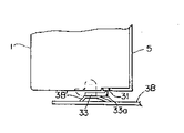
제8도는 카세트의 오른쪽 측면도.8 is a right side view of the cassette.
제9도는 카세트의 덮개가 덮힌 상태(카세트 삽입시)를 도시한 오른쪽 측면도.Fig. 9 is a right side view showing the cover of the cassette (when inserting the cassette).
제10도는 이 제9도에 관한 상태의 부분 평면도.FIG. 10 is a partial plan view of a state of this FIG.
제11도는 이 제10도에 관한 상태에서 홀더가 수평으로 이동하여 덮개 개폐스위치용 암이 작동한 상태를 도시한 부분 평면도.FIG. 11 is a partial plan view showing a state in which the holder for the cover opening / closing switch operates by moving the holder horizontally in the state according to FIG.
제12도는 이 제11도에 관한 상태에서 다시 수평으로 이동하여 카세트의 덮개가 들어올려진 상태를 도시한 오른쪽 측면도.FIG. 12 is a right side view showing a state in which the lid of the cassette is lifted by moving horizontally again in the state of FIG.
제13도는 상기 카세트 장착장치의 오른쪽 측면도.13 is a right side view of the cassette mounting apparatus.
제14도∼제16도는 상기 카세트 장착장치의 카세트 잘못 삽입 방지기구를 설명하는 것이며,14 to 16 illustrate a cassette wrong insertion prevention mechanism of the cassette mounting apparatus,
제14도는 카세트가 삽입되어 있지 않은 상태의 카세트 장착장치를 도시한 대략을 나타내는 오른쪽 측면도.Fig. 14 is a right side view showing the outline of a cassette mounting apparatus in a state where a cassette is not inserted.
제15도는 카세트가 삽입되었을때의 상태를 도시한 중요부의 사시도.Fig. 15 is a perspective view of an essential part showing a state when a cassette is inserted.
제16도는 카세트가 완전히 삽입되어 전송이 가능하게 된 상태를 도시한 대략을 나타내는 왼쪽 측면도.Fig. 16 is a left side view showing an approximation showing a state in which the cassette is fully inserted so that transmission is possible.
본 발명은 비디오 테이프 레코더와 같은 자기기록 재생장치의 카세트 장착장착에 관한 것이다. 본 발명의 카세트 장착장치는 특히 카세트를 홀드하는 카세트홀더를, 모오터의 구동력을 이용해서, 수평과 수직의 2방향, 즉 카세트홀더(카세트)를 처음에 수평방향으로 이동하고, 이어서 수직방향으로 이동하는 모오터 구동식 카세트 장착장치, 소위 프론트 로딩형(front loading type)의 카세트 장착장치에 가장 적합한 것이다.The present invention relates to cassette mounting of a magnetic recording / playback apparatus such as a video tape recorder. In particular, the cassette mounting apparatus of the present invention moves a cassette holder for holding a cassette in a horizontal and vertical two directions, that is, a cassette holder (cassette) in a horizontal direction, first by using a driving force of a motor, and then in a vertical direction. It is most suitable for moving motor driven cassette mounting devices, so-called front loading type cassette mounting devices.
이와 같은 프론트 로딩형의 카세트 장착장치(이하 프론트 로딩가구라 한다)는 예를 들면 제1도 내지 제4도에 도시한 것과 같은 구성으로 되어 있다.Such a front loading cassette mounting apparatus (hereinafter referred to as front loading furniture) has a configuration as shown in FIGS. 1 to 4, for example.
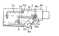
제1도는 종래의 프론트 로딩기구의 개략 평면도, 제2도는 그 왼쪽 측면도, 제3도는 그 중요부의 분해 사시도, 제4도는 그 중요부의 단면도를 도시한다. 즉 도시되어 있는 것과 같이, 프론트 로딩기구는 왼쪽 사이드 브래키트(bracket) 3a와 오른쪽 사이드 브래키트 3b와의 사이에 카세트홀더 2를 갖고 있다. 그 카세트홀더 2는 샤프트(shaft) 11a, 11b, 12a, 12b와 로울러(roller) 14a, 14b, 15a, 15b를 거쳐서 상기 왼쪽과 오른쪽 사이드 브래키트 3a와 3b에 형성된 L자 상태의 가이드(guide) 구멍(slit) G1, G1과 G2, G2에 해당 구멍에 따라서 이동이 가능하게 지지되어 있다. 브래키트 3a, 3b는 메인 샤시(main chassis) 3에 고정되어, 카세트 장착장치 전체의 위치결정 부재로도 되어 있다. 샤프트 11a, 11b, 12a, 12b는 홀더 2의 양쪽면에 파묻혀(embed)있다. 로울러 14a, 14b, 15a, 15b는 샤프트 11a, 11b, 12a, 12b에 끼워져서, 그 일부는 브래키트 3a, 3b의 가이드 구멍 G1, G2에 걸어맞춤되어 있다. 21a, 21b와 22a, 22b는 동기(同期)샤프트 25에 부착된 구동기어와 구동암을 나타내며, 그 암에는 상기 로울러 14a, 14b가 삽입되는 긴 구멍(hole) H가 형성되어 있다. 구동기어 21a, 21b는 도시하지 않았으나, 모오터의 동력을 받아서 회전하도록 구성되어 있다. 동기 샤프트 25는 좌우 브래키트 3a, 3b에 회전이 자유롭게 설치되어 있다.FIG. 1 is a schematic plan view of a conventional front loading mechanism, FIG. 2 is a left side view thereof, FIG. 3 is an exploded perspective view of the essential part thereof, and FIG. 4 is a sectional view of the essential part thereof. That is, as shown, the front loading mechanism has a
다음에 그 동작을 간단히 설명한다.The operation is briefly described next.
카세트 1이 제1도의 화살표의 방향으로 카세트홀더 2에 삽입되어 올려놓여지면, 카세트홀더 2의 움직임에 의해 검지 스위치(도시하지 않음)가 ON한다. 이로 인해서 모오터(도시하지 않음)가 구동되어, 이 구동력은 도시하지 않았으나, 워엄기어(worm gear)등의 감속기구를 거쳐서 예를 들면 기어 21a에 전달된다. 기어 21a가 반시계 방향으로 회전하면, 구동암 22a도 같은 방향으로 회동하며, 또 이에 따라서 기어 21b, 구동암 22b도 마찬가지로 회동하여, 카세트홀더 2는 그 암 22a에서 왼쪽방향의 힘을 받어, 카세트 1을 올려놓은 상태로 가이드 구멍 G1, G1과 G2, G2에 안내되어서, 수평으로 안쪽으로 운반된다. 사전에 정해진 거리만큼 수평방향으로 이동하면, 카세트홀더 2는 상기 가이드 구멍 G1, G1과 G2, G2의 수직부에 안내되어서 수직으로 아랫방향으로 이송된다.When the cassette 1 is inserted and placed in the
이와 같이 해서 카세트 1이 소정의 위치에 장착되면, 카세트 1내에 수납되어 있는 자기테이프(도시하지 않음)는 VTR(Video Tape Recorder)의 테이프 로딩기구(도시하지 않음)에 의해 인출되어, 기록과 재생용의 헤드를 올려놓은 실린더(도시하지 않음)에 감겨진다. 그리고 그 자기테이프에 기록이 행하여지든지, 그 자기테이프에서 재생이 행하여지든지 한다.In this way, when the cassette 1 is mounted at a predetermined position, the magnetic tape (not shown) stored in the cassette 1 is taken out by a tape loading mechanism (not shown) of the VTR (Video Tape Recorder) to record and reproduce. It is wound up in the cylinder (not shown) which put the dragon head. The recording may be performed on the magnetic tape, or the reproduction may be performed on the magnetic tape.
상술과 같이, 종래의 카세트 장착장치는 홀더 2를 구동하는 회동부재, 즉 구동암 22a와 구동암 22b가 각각 브래키트 3a와 브래키트 3b의 바깥쪽에 있으므로, 필연적으로 장치가 대형화하여, 자기기록 재생장치의 소형화, 박형화(薄形化), 경량화를 조해하는 문제점으로 되고 있었다.As described above, in the conventional cassette mounting apparatus, since the rotating member for driving the
본 발명의 목적은 상기한 종래 기술의 문제점을 개선하여, 자기기록 재생장치의 소형화가 이루어지는 카세트 장착장치를 제공하는데 있다.SUMMARY OF THE INVENTION An object of the present invention is to provide a cassette mounting apparatus in which the magnetic recording and reproducing apparatus can be miniaturized by improving the above problems of the prior art.
본 발명에 의하면 회동부재를 카세트 유지부재와 브래키트와의 사이에 있고, 카세트덮개 개폐기구와 카세트 잘못 삽입 방지기구에 간섭하지 않는 위치에 배설하는 것에 의해, 카세트 장착장치의 폭을 좁게하는 것이 가능하게 되어, 자기기록 재생장치의 소형화가 이루어진다.According to the present invention, it is possible to narrow the width of the cassette mounting apparatus by disposing the rotating member at a position between the cassette holding member and the bracket and not interfering with the cassette lid opening and closing mechanism. As a result, the magnetic recording and reproducing apparatus can be miniaturized.
[실시예]EXAMPLE
다음에 본 발명을 실시예에 의해서 설명한다.Next, an Example demonstrates this invention.
제5도는 본 발명의 실시예 1에 관한 카세트 장착장치의 개략도, 제6도는 제5도에 관한 카세트 장착장치의 왼쪽의 상세를 도시한 부분 단면도, 제7도는 같은 왼쪽의 분해 사시도, 제8도∼제12도는 상기 카세트 장착장치의 카세트덮개의 개폐기구를 설명하는 것이며, 제8도는 카세트의 개략의 오른쪽 측면도, 제9도는 카세트의 덮개가 닫힌 상태(카세트 삽입시)를 도시한 오른쪽 측면도, 제10도는 이 제9도에 관한 상태의 부분 평면도, 제11도는 이 제10도에 관한 상태에서 홀더가 수평 이동하여, 덮개 개폐스위치용 암이 작동한 상태를 도시한 부분 평면도, 제12도는 이 제11도의 상태에서 다시 수평 이동해서 카세트의 덮개가 들어올려진 상태를 도시한 오른쪽 측면도, 제13도는 상기 카세트 장착장치(제1도에 있어서 아래부분)을 도시한 대략을 나타내는 오른쪽 측면도, 제14도 내지 제16도는 상기 카세트 장착장치의 카세트 잘못 삽입 방지기구를 설명하는 것이며, 제14도는 카세트가 삽입되어 있지 않은 상태의 카세트 장착장치를 도시한 대략을 나타내는 왼쪽 측면도, 제15도는 카세트가 삽입되었을 때의 상태를 도시한 중요부의 사시도, 제16도는 카세트가 완전히 삽입되어 반송이 가능하게 된 상태를 도시한 대략을 나타내는 왼쪽 측면도면이다. 각 도면에 있어서, 제1도 내지 제4도와 같은 번호를 붙인 것은 같은 부분이다.FIG. 5 is a schematic diagram of a cassette mounting apparatus according to Embodiment 1 of the present invention, FIG. 6 is a partial cross-sectional view showing details of the left side of the cassette mounting apparatus according to FIG. 5, FIG. 7 is an exploded perspective view of the same left side, and FIG. Fig. 12 illustrates the opening and closing mechanism of the cassette cover of the cassette mounting apparatus, Fig. 8 is a right side view of the outline of the cassette, and Fig. 9 is a right side view showing the state where the lid of the cassette is closed (when cassette is inserted). FIG. 10 is a partial plan view of the state of FIG. 9, and FIG. 11 is a fragmentary plan view of a state in which the holder is moved horizontally in the state of FIG. Right side view showing a state in which the lid of the cassette is lifted horizontally again in the state of 11 degrees, and FIG. 13 is a right side showing the approximation showing the cassette mounting apparatus (lower part in FIG. 1). 14 to 16 show a cassette insertion prevention mechanism of the cassette mounting apparatus, and FIG. 14 is a left side view showing an approximate view showing a cassette mounting apparatus without a cassette inserted, and FIG. Fig. 16 is a left side view showing an outline showing a state in which the cassette is fully inserted and the conveyance is possible, showing the state when the cassette is inserted. In each figure, the same code | symbol is attached | subjected with the same number as FIG.
이 카세트 장착장치의 개요는 상자 상태의 카세트 유지부재에 관한 카세트홀더 2의 양쪽면에 마련한 저지부에 관한 로울러 14a, 15a(이상 왼쪽), 14b, 15b(이상 오른쪽)가 홀더 2의 양쪽에 배설되며, 또한 자기기록 재생장치의 메인 샤시 3에 고정된 1조의 브래키트 3A(왼쪽), 3B(오른쪽)에 뚫어 설치한 가이드 구멍 G(상세한 것은 후술)에 걸어맞춤시켜, 회동부재에 관한 구동암 22a(왼쪽), 22b(오른쪽)에 의해서 상기 로울러를 상기 가이드 구멍에 따라서 구동하는 것에 의해 자기기록 재생장치 본체에 마련된 카세트 삽입용의 삽입구에서 홀더 2내에 삽입하여 장착한 카세트 1을 본체내의 소정 위치로 이송하도록 한 카세트 장착장치로서 상기 구동암 22a를 홀더 2와 브래키트 3A와의 사이에 또 사이 구동암 22b를 홀더 2와 브래키트 3B와의 사이에 배설하도록 한 것이다.The outline of this cassette mounting apparatus is that rollers 14a, 15a (more than left), 14b, and 15b (more than right), which are provided on both sides of
그리고, 상세한 것을 카세트 장착장치의 왼쪽에 대해서 제6도, 제7도를 이용하여 설명한다. 구동암 등에 관해서는 오른쪽도 마찬가지의 구성이기 때문에 그 설명은 생략한다.The details of the left side of the cassette mounting apparatus will be described with reference to FIGS. 6 and 7. The driving arm and the like have the same configuration as the right side, and thus description thereof is omitted.
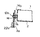
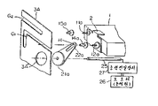
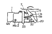
제6도에 있어서, 카세트 1과 홀더 2와 브래키트와의 사이에 구동암 22a를 포함하는 카세트홀더 구동수단이 배치되어 있다. 따라서 상기한 종래의 카세트 장착장치는 구동암 22a와 브래키트와의 위치관계가 반대로 되어 있으며, 제7도에 도시한 것과 같이 홀더 2위에 파묻힌 샤프트 12a에 회전이 자유롭게 설치된 로울러 14a가 구동암 22a의 긴 구멍 H를 통해서 브래키트 3A의 L자 형상의 가이드구멍 G1에 걸어맞춤하고 있다. 또 샤프트 11a에 회전이 자유롭게 설치된 로울러 15a는 브래키트 3A의 L자 형상의 가이드 구멍 G2에 걸어맞춤하고 있다. 구동암 22a와 함께 샤프트 25에 설치된 기어 21a는 브래키트 3A에 마련된 구멍 3A"에 제5도에 도시한 것과 같이 삽입되어, 상술한 모오터(동력원)(26)에 감속기구(동력전달수단((27)을 거쳐서 결합되어 있다. 홀더 2와 브래키트 3A와의 사이에는 카세트 잘못 삽입 방지기구(상세한 것은 후술)가 배설되어 있으므로, 브래키트 3A, 3B와 홀더 2의 양쪽면과의 사이의 거리는 종래의 카세트 장착장치와 동일하며, 더욱이 좁게할 수가 없으므로, 구동암 22a, 22b를 브래키트 3A, 3B의 안쪽에 배설하는 것에 의해, 본 카세트 장착장치는 폭을 좁게하도록 되어 있다. 구동암 22a, 22b는 물론 상기 카세트 잘못 삽입 방지기구, 카세트덮개 개폐기구와 간섭하는 일은 없다.In Fig. 6, the cassette holder driving means including the drive arm 22a is disposed between the cassette 1, the
이와 같이 구성한 본 카세트 장착장치의 동작은 종래의 것과 마찬가지로 구동암 22a에 의해서 홀더 2의 로울러 14a, 15a를 브래키트 3A의 가이드구멍 G1에 따라서 구동하며, 이것과 동기해서 구동암 22b에 의해서 로울러 14b, 15b를 브래키트 3B의 가이드 구멍에 따라서 구동하는 것에 의해 삽입구에서 홀더 2에 삽입된 카세트 1을 본체내에 소정위치로 이송할 수가 있다. 구동암 22a, 22b는 모오터 등의 동력을 받아서 회전한다.The operation of the cassette mounting apparatus configured as described above drives the rollers 14a and 15a of the
다음에 상기 카세트덮개 개폐기구를 제8도 내지 제12도를 이용하여 설명한다.Next, the cassette lid opening and closing mechanism will be described with reference to FIGS.
카세트 1에는 주지와 같이 내부의 테이프 6을 보호하는 덮개 5가 설치되어 있으며, 또 이 덮개 5의 로크(lock)를 빠지게 하기 위한 개폐스위치 31(제10도 참조)가 장착되어 있다. 자기기록 재생장치가 기록재생을 행할때에는 이 덮개 5를 열지 않으면 안되나, 본 실시예의 카세트 장착장치는, 그 여는 동작전에 카세트 1의 삽입후, 수평 이동을 행할때에, 사전에 덮개 5를 수 mm 여는 구성으로 되어 있다. 주지와 같이 카세트 1은 상기 소정위치에 유지된 후, 가이드 로울러에 의해, 테이프 6이 인출되어 실린더에 감겨진다. 이 테이프 6의 구동은, 그 테이프 6이 캡스턴(capstan)과 핀치 로울러(pinch roller)에 끼워져서 행하여진다. 여기서 카세트 1은 상기 소정위치로 이송되기 전에 테이프 6이 상기 가이드 로울러나 캡스턴을 넘는 것과 같이 반송되지 않으면 안된다. 그러나 제8도에 도시한 것과 같이, 카세트 1의 내부에 수납되는 테이프 6의 아래끝 보다도 덮개 5의 아래끝의 쪽이 낮기 때문에, 카세트 1의 수평 이동중에 사전에 덮개 5를 약간 열어서 테이프 6의 아래끝과 대략 같이 되도록 하면, 테이프 6이 상기 가이드 로울러와 캡스턴등의 부재를 넘을 수가 있고, 또한 카세트 장착장치를 박형화할 수가 있다.The cassette 1 is provided with a
그 구성은 다음과 같이 되어 있다.The configuration is as follows.
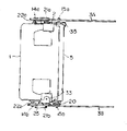
덮개 5를 사전에 여는 준비로서 카세트 1의 개폐스위치 31을 눌러서 로크를 빠지게 하는 것이지만, 이 눌름 동작은 덮개 개폐스위치용 암 33을 사용하여 행한다. 이 암 33은 제12도, 제13도에 도시한 것과 같이 홀더 2의 상하 양면에 회동지축(支軸)을 갖고, 이 회동지축의 둘레에 회동이 자유롭게 지지되어 있다. 제10도는 카세트 1의 삽입시, 또는 배출이 끝났을때의 상태이며, 카세트 1의 반송 동작의 초기 상태를 도시한다. 덮개 개폐스위치용 암 33의 상부에 마련된 배모양(船形)의 슬라이드부분이, 브래키트 3B에서의 절기(切起)부분 3B'(돌기부)에 올라 앉아서, 덮개 개폐스위치용 암 33의 중앙의 개폐스위치 31과의 맞닿음부 33a는 개폐스위치 31에 접속되어 있지 않다. 이것은 덮개 개폐스위치용 암 33에 개폐스위치 31이 항상 맞닿음하고 있으면, 카세트 1의 출입할때에 걸리는 감각이 남기 때문에 카세트 1의 출입할때에는 덮개 개폐스위치용 암 33을 떼어서 착탈감이 없도록 한 것이다. 카세트 1의 수평 이송이 시작하면, 덮개 개폐스위치용 암 33이 브래키트 3B의 절기로부터 떨어져, 제11도의 화살표로 표시한 반시계 방향의 회전력을 부여하여 카세트 1의 개폐스위치 31을 눌러 덮개 5의 개폐가 가능하게 된다. 개폐 암 20(상세한 것은 후술)과 덮개 개폐스위치용 암 33과의 사이에는 스프링 32가 걸려져 있으며, 개폐암 20에는 제12도의 시계 방향의 부세력이 또 덮개 개폐스위치용 암 33에는 제11도의 반시계 방향의 부세력이 각각 부여되어 있다. 상기 개폐 암 20은 제12도, 제13도에 도시한 것과 같이 샤프트 11b에 회동이 자유롭게 설치되어 있고, 그 아래쪽 끝이 카세트 1의 덮개 5에 대략 접하는 위치로 유지되어 있다. 홀더 2가, 제11도의 상태에서 다시 수평 이동을 개시하면, 개폐 암 20의 위쪽 끝이 카세트 장착장치의 천판(天板)(ceiling plate) 7에 맞닿음하여, 제12도에 화살표로 도시한 것과 같이, 반시계 방향의 회전력이 부여되어서 회동하면, 제12도에 도시한 것과 같이, 개폐 암 20의 아래쪽 끝에 접하고 있던 덮개 5가 들어올려져, 수mm 열린다.Although the lock is released by pressing the on / off
상기한 카세트덮개 개폐기구와 구동암 22b와의 위치관계는 제13도에 도시한 것과 같이 되어 있으며 개폐 암 20, 덮개 개폐스위치용 암 33은 삽입구(도시하지 않음)에서 비교적 먼 위치에 있는데 대해서 로울러 14b는 상기 삽입구에 가깝기 때문에, 구동암 22b가 개폐암 20, 덮개 개폐스위치용 암 33과 간섭하는 일은 없다.The positional relationship between the cassette cover opening and closing mechanism and the driving
최후로 상기 카세트 잘못 삽입 방지기구를 제14도 내지 제16도를 이용하여 설명한다.Finally, the cassette insertion prevention mechanism will be described with reference to FIGS. 14 to 16. FIG.
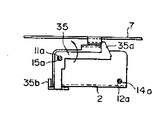
제14도에 있어서, 35는 샤프트 11a에 구동이 자유롭게 설치된 후크(hook)암이며, 이 후크암 35a는 스프링(도시하지 않음)에 의해 항상 반시계 방향으로 부세되어 있다. 후크암 35의 상부의 후크 35a는 천판 7과 걸어맞춤하여 카세트 1이외의 것이 잘못해서 삽입되는지, 또는 카세트 1의 상하가 역으로 들어갔을 경우에는, 상기 후크 35a가 스톱퍼(stopper)로 되어서 카세트 1의 반송 동작이 스톱된다. 카세트 1의 덮개 5에는 제15도에 도시한 것과 같이, 카세트 삽입이 끝난 것을 검출하는 홈 1a가 마련되어 있고, 후크암 35는 카세트 1의 삽입과 동시에, 상기 홈내에서 카세트 1과 맞닿음하여, 샤프트 11a를 중심으로 하여 회동한다. 이동작에 따라서 제16도와 같이 후크암 35의 후크부분이 내려가서, 천판 7과의 걸어맞춤이 빠져서 카세트 반송이 가능하게 된다.In FIG. 14, 35 is a hook arm in which drive is freely provided in the shaft 11a, and this
Claims (5)
Applications Claiming Priority (2)
| Application Number | Priority Date | Filing Date | Title |
|---|---|---|---|
| JP80171 | 1986-04-09 | ||
| JP61080171A JP2544345B2 (en) | 1986-04-09 | 1986-04-09 | Cassette mounting device |
Publications (2)
| Publication Number | Publication Date |
|---|---|
| KR870010523A KR870010523A (en) | 1987-11-30 |
| KR910000570B1 true KR910000570B1 (en) | 1991-01-26 |
Family
ID=13710884
Family Applications (1)
| Application Number | Title | Priority Date | Filing Date |
|---|---|---|---|
| KR1019870003084A KR910000570B1 (en) | 1986-04-09 | 1987-04-01 | Cassette loading mechanism |
Country Status (5)
| Country | Link |
|---|---|
| US (1) | US4794477A (en) |
| EP (1) | EP0240922B1 (en) |
| JP (1) | JP2544345B2 (en) |
| KR (1) | KR910000570B1 (en) |
| DE (1) | DE3782444T2 (en) |
Families Citing this family (12)
| Publication number | Priority date | Publication date | Assignee | Title |
|---|---|---|---|---|
| JPH0656707B2 (en) * | 1987-07-01 | 1994-07-27 | 富士写真フイルム株式会社 | Magnetic tape cassette inspection method and apparatus |
| DE311390T1 (en) * | 1987-10-07 | 1989-11-16 | Victor Company Of Japan, Ltd., Yokohama, Kanagawa, Jp | TAPE CASSETTE LOADING SYSTEM. |
| US5060094A (en) * | 1987-11-20 | 1991-10-22 | Goldstar Co., Ltd. | Cassette loading apparatus for digital audio tape recorder |
| DE3853638T2 (en) * | 1987-12-09 | 1996-01-25 | Mitsubishi Electric Corp | Tape cartridge loading mechanism in a tape player. |
| US5196971A (en) * | 1988-12-28 | 1993-03-23 | Kabushiki Kaisha Toshiba | Tape loading mechanism for use in magnetic recording/reproducing apparatus having tape control features for preventing damage to tape |
| JPH02177163A (en) * | 1988-12-28 | 1990-07-10 | Toshiba Corp | Cassette loader |
| US5152477A (en) * | 1990-08-01 | 1992-10-06 | Yeh Tsun W | Electronic detection device for detecting the ending of the rewinding of a video cassette rewinder |
| KR930007441Y1 (en) * | 1990-11-23 | 1993-10-25 | 삼성전자 주식회사 | Cassette lid opening apparatus |
| JP2601685Y2 (en) * | 1993-08-26 | 1999-11-29 | ミツミ電機株式会社 | Cassette tape drive |
| KR970001987B1 (en) * | 1993-09-15 | 1997-02-20 | 대우전자 주식회사 | Cassette reed pre-open apparatus of tape recorder |
| JPH07130057A (en) * | 1993-10-29 | 1995-05-19 | Canon Inc | Cassette lid opening and closing device |
| JPH0927157A (en) * | 1995-07-07 | 1997-01-28 | Matsushita Electric Ind Co Ltd | Tape cassette lid opening/closing device |
Family Cites Families (9)
| Publication number | Priority date | Publication date | Assignee | Title |
|---|---|---|---|---|
| JPS5245382B2 (en) * | 1972-08-28 | 1977-11-15 | ||
| FR2221783B1 (en) * | 1973-03-16 | 1977-09-16 | Staar Sa | |
| JPS5087010A (en) * | 1973-11-30 | 1975-07-12 | ||
| US4257075A (en) * | 1979-03-23 | 1981-03-17 | Minnesota Mining And Manufacturing Company | Tape magazine and recording and/or playback machine with improved magazine locating and loading structure |
| JPS5868265A (en) * | 1981-10-19 | 1983-04-23 | Hitachi Ltd | Cassette loading device |
| JPS58166571A (en) * | 1982-03-26 | 1983-10-01 | Hitachi Ltd | Cassette loading device |
| US4583138A (en) * | 1982-04-12 | 1986-04-15 | Mikiharu Imazaike | Device for transporting cassette |
| JPS5992466A (en) * | 1982-11-17 | 1984-05-28 | Canon Inc | Recording or reproducing device |
| JPS60231955A (en) * | 1984-04-27 | 1985-11-18 | Mitsubishi Electric Corp | Tape cassette loading device |
-
1986
- 1986-04-09 JP JP61080171A patent/JP2544345B2/en not_active Expired - Lifetime
-
1987
- 1987-04-01 DE DE8787104827T patent/DE3782444T2/en not_active Expired - Fee Related
- 1987-04-01 KR KR1019870003084A patent/KR910000570B1/en not_active IP Right Cessation
- 1987-04-01 EP EP87104827A patent/EP0240922B1/en not_active Expired - Lifetime
- 1987-04-09 US US07/036,374 patent/US4794477A/en not_active Expired - Lifetime
Also Published As
| Publication number | Publication date |
|---|---|
| DE3782444D1 (en) | 1992-12-10 |
| KR870010523A (en) | 1987-11-30 |
| JP2544345B2 (en) | 1996-10-16 |
| DE3782444T2 (en) | 1993-05-19 |
| US4794477A (en) | 1988-12-27 |
| EP0240922B1 (en) | 1992-11-04 |
| EP0240922A2 (en) | 1987-10-14 |
| EP0240922A3 (en) | 1989-10-25 |
| JPS62239361A (en) | 1987-10-20 |
Similar Documents
| Publication | Publication Date | Title |
|---|---|---|
| US5220552A (en) | Disc apparatus with a guide for disk insertion | |
| KR910000570B1 (en) | Cassette loading mechanism | |
| KR910014934A (en) | Disc player and disc loading device | |
| US5103357A (en) | Tape recorder including a device for opening a lid of tape cassette during the loading thereof | |
| EP0600704B1 (en) | Cassette accommodating type electronic equipment | |
| KR930008277B1 (en) | Cassette loading mechanism of a magentic recording/reproducing apparatus | |
| KR930000685B1 (en) | Cassette loading mechanism | |
| KR100189478B1 (en) | Loading mechanism for a recording/reproducing apparatus | |
| KR920010459B1 (en) | Cassette housing device | |
| JPH0371465A (en) | Magnetic recording and reproducing device | |
| JPH0258755A (en) | Cassette loading device | |
| JPS6355754A (en) | Magnetic recording and reproducing device | |
| US7012779B2 (en) | Recording and reproducing device | |
| JPH05266555A (en) | Information recording and reproducing device | |
| JP2509076B2 (en) | Magnetic recording / reproducing device | |
| JPH0351794Y2 (en) | ||
| JPH08235705A (en) | Cassette loading device | |
| JP2876855B2 (en) | Tape recorder | |
| JPH0510265Y2 (en) | ||
| JPS6343672Y2 (en) | ||
| JPH06295556A (en) | Tape cassette | |
| JP2583240Y2 (en) | Magnetic recording / reproducing device | |
| JPH09171652A (en) | Cassette loading device | |
| JPH0430691Y2 (en) | ||
| JPH0441479Y2 (en) |
Legal Events
| Date | Code | Title | Description |
|---|---|---|---|
| A201 | Request for examination | ||
| E902 | Notification of reason for refusal | ||
| G160 | Decision to publish patent application | ||
| E701 | Decision to grant or registration of patent right | ||
| GRNT | Written decision to grant | ||
| FPAY | Annual fee payment |
Payment date: 20070103 Year of fee payment: 17 |
|
| EXPY | Expiration of term |