KR900005748B1 - Cover and structure of light self emitting type - Google Patents
Cover and structure of light self emitting type Download PDFInfo
- Publication number
- KR900005748B1 KR900005748B1 KR1019850007826A KR850007826A KR900005748B1 KR 900005748 B1 KR900005748 B1 KR 900005748B1 KR 1019850007826 A KR1019850007826 A KR 1019850007826A KR 850007826 A KR850007826 A KR 850007826A KR 900005748 B1 KR900005748 B1 KR 900005748B1
- Authority
- KR
- South Korea
- Prior art keywords
- signal
- light
- self
- light emitting
- cover
- Prior art date
Links
Images


Classifications
-
- G—PHYSICS
- G08—SIGNALLING
- G08G—TRAFFIC CONTROL SYSTEMS
- G08G1/00—Traffic control systems for road vehicles
Abstract
Description
제1도는 본 발명의 자체 발광 표지의 사시도.1 is a perspective view of a self-luminous label of the present invention.
제2a도는 본 발명의 구조체중에 키이 스테이션(key station)이 되는 자체 발광 표지의 블록 회로도.Figure 2a is a block circuit diagram of a self-illuminating beacon that is a key station in the structure of the present invention.
제2b도는 동(同)구조체중의 중계용 자체 발광 표지의 블록 회로도.2B is a block circuit diagram of a relay self-emitting label in the same structure.
제3도는 본 발명의 자체 발광 표지 구조체의 사시도.3 is a perspective view of a self-emitting label structure of the present invention.
제4도-제10도는 본 발명의 자체 발광 표지의 발전적 실시예로서,4 to 10 are developmental embodiments of the self-luminous label of the present invention.
제4도는 태양전지 모듈(module)을 씌운 투광성커버를 반타원구(王求)형상으로 한 태양전지 모듈과 투광성 커버를 부착하지 않은 태양전지 모듈의 출력 전류와 시간의 경과와의 관계를 나타내며,4 shows the relationship between the output current of the solar cell module having the translucent cover with the solar cell module and the solar cell module without the translucent cover with the passage of time.
제5도는 출력전류와 태양의 조도(照度)의 변화의 관계를 나타낸 제4도와 동일한 도면.FIG. 5 is the same as FIG. 4 showing the relationship between the output current and the change in the illuminance of the sun.
제6도는 출력전류의 증가율을 나타낸 제4도와 동일한 도면.6 is the same as FIG. 4 showing the increase rate of the output current.
제7도는 태양전지 모듈을 씌운 투광성 커버의 다른 발전예를 나타낸 종단면도.7 is a longitudinal sectional view showing another example of power generation of a light-transparent cover overlaid with a solar cell module.
제8도는 제7도의 예의 기능을 나타낸 설명도.FIG. 8 is an explanatory diagram showing the function of the example of FIG.
제9도는 발광 다이오드를 씌운 투광성 커버의 발전 실시예를 나타낸 종단면도.9 is a longitudinal sectional view showing a power generation embodiment of a light-transmissive cover with a light emitting diode.
제10도는 제9도의 예의 기능을 나타낸 설명도.10 is an explanatory diagram showing the function of the example of FIG.
* 도면의 주요부분에 대한 부호의 설명* Explanation of symbols for main parts of the drawings
1 : 자체 발광 표지 2 : 태양전지 모듈1 self-
3 : 투광성 커버 4 : 발광 다이오드3: transparent cover 4: light emitting diode
5 : 점등기 7 : 반사기5: lighter 7: reflector
8 : 제어신호 발신장치 9 : 제어신호 수신장치8: control signal transmitter 9: control signal receiver
15 : 발광 제어회로 16 : 클럭 회로15 light
17 : 복조(復調)회로 18 : 점등판별회로17: demodulation circuit 18: lighting discrimination circuit
19 : 변조신호 발생회로 21 : 반사층19 modulation
본 발명은 태양전지를 전원으로 사용하여 여러개의 발광 다이오드를 점등 또는 점멸시켜서 운전자등의 주의를 환기시키는 표지 및 그 구조체에 관한 것이다.BACKGROUND OF THE INVENTION 1. Field of the Invention The present invention relates to a sign and a structure for calling attention of a driver by lighting or flashing a plurality of light emitting diodes using a solar cell as a power source.
도로 모퉁이 부분등의 표시 꼬불꼬불한 도로의 시선유도의 목적으로 설치되는 자체 발광 표지는 상용 전원, 건전지 등을 전원으로 하고 있으며, 특히 상업 전원 설비가 없는 도로 등에서 사용하는 경우는 건전지 등을 정기적으로 교환할 필요가 있어서 보수(補修)작업이 많았다.Signs on the corners of the road The self-illuminating signs, which are installed for the purpose of guiding the appearance of winding roads, are powered by commercial power sources and batteries, especially when used on roads without commercial power facilities. There was a lot of repair work because of the need for replacement.
그래서 고안된 것이 태양전지를 전원으로 사용한 자체 발광 표지이다.That is why the self-luminous label using solar cells as a power source was designed.
(일본 실개소 52-95389호 공보, 일본 특개소 52-89081호 공보, 일본 특개소 52-89082호 공보 참조)(See Japanese Patent Application Laid-Open No. 52-95389, Japanese Patent Application Laid-Open No. 52-89081, Japanese Patent Application Laid-Open No. 52-89082)
이들 자체 발광 표지의 점등 및 소등 스위치로서는 태양전지를 발광 다이오드의 전원으로 사용하는 동시에 주위의 명암을 검지하는 장치로서 사용하고, 검출한 신호로 발광 다이오드를 작동시키는 것이 행하여지고 있다.As the on / off switch of these self-luminous labels, a solar cell is used as a power source for a light emitting diode and at the same time, the device is used to detect ambient light and operate the light emitting diode with the detected signal.
즉, 태양전지의 출력 전압의 고저를 신호로 변환하고 있다.That is, the height of the output voltage of a solar cell is converted into a signal.
예를들면, 주간 태양전지의 출력 전압이 높을때는 출력전압은 축전지에 충전되어 일몰후 그 출력전압이 일정한 값이하로 되면 축전지로 부터 방전이 행하여져 발광 다이오드가 점등 또는 점멸한다.For example, when the output voltage of the daytime solar cell is high, the output voltage is charged in the storage battery, and when the output voltage becomes lower than a constant value after sunset, the discharge is performed from the storage battery so that the light emitting diode is turned on or blinks.
(이하, 점멸만을 예로든다)(Hereafter, only flashing is taken as an example)
또한, 일출이 되어 태양전지를 출력 전압이 일정한 값 이상이 되면 축전지로 부터의 방전이 정지되며, 동시에 태양전지의 출력이 축전지에 충전된다.In addition, when the output voltage of the solar cell reaches a certain value or more at sunrise, discharge from the battery is stopped, and at the same time, the output of the solar cell is charged to the battery.
실제, 자체 발광 표지가 설치되는 곳은 도로가 매우 꼬불꼬불한 장소나 교통사고가 많이 발생되는 지대등으로서, 그 설치는 일정한 간격을 두고 여러개를 일열로 줄지어 계속되도록 설치되는 것이 보통이다.In fact, the place where the self-luminous sign is installed is a place where the road is very winding or a zone where a lot of traffic accidents occur, and the installation is usually installed so that several lines are arranged in a row at regular intervals.
이와같은 일로 인해서 나무등의 장해물의 그늘에 설치한 자체 발광 표지의 발광 다이오드만이 일찍부터 점멸을 개시하거나 또한 개개의 점멸 주기를 일정하게 설치해 두어도 여러개의 자체 발광 표지를 전체로 보면 각자 발광 표지가 시간적으로 일정하지 않게 점멸해 버려서 통행차를 당황하게 하는등 바른 교통정보를 제공할 수가 없다는 결점이 있었다.Because of this, only the LEDs of the self-emissive label installed in the shade of obstacles such as trees start flashing early, or even if the individual flashing cycles are constantly installed, if you see several self-emitting labels as a whole, There was a drawback that it could not provide correct traffic information, such as flashing inconsistently over time, causing embarrassment of traffic.
본 발명은 전술한 결점을 해소하고 태양전지를 전원으로한 최대의 효과, 즉 설치의 자유도(전원공급의 배선이 불필요)를 유지하면서 여러개를 일열로 줄지어 계속 되도록 설치한 자체 발광 표지의 점멸 동작에 연관 관계를 갖게하여 올바른 교통정보를 통행차에게 제공하는 자체 발광 표지를 제공하는데 있다.The present invention solves the above-mentioned drawbacks and maintains the maximum effect of using a solar cell as a power source, that is, the flashing of a self-luminous label installed so as to continue several lines in a row while maintaining the degree of freedom of installation (no power supply wiring is required). It is to provide a self-luminous sign that has a relationship to the operation to provide the correct traffic information to the traffic.
전술한 목적은 점등기 표면의 표지면에 투광성 커버로 씌운 여러개의 발광 다이오드를 점멸이 자유롭게 구비하고, 전술한 점등기의 윗면에는 투광성 커버로 씌운 태양전지 모듈이 있으며 또한 전술한 발광 다이오드의 점등 혹은 점멸의 제어 신호의 발신 장치 및 또는 수신장치를 구비한 점멸구성에 의하여 달성된다.The above-described object is provided with a plurality of light emitting diodes freely flickered on the cover surface of the light emitter cover, and a solar cell module covered with the light transmissive cover on the upper surface of the above light emitter. A flashing arrangement having a flashing control signal transmitting device and / or a receiving device is achieved.
이하, 본 발명의 자체 발광 표지의 실시예를 도면에 의거하여 상세히 설명하기로 한다.Hereinafter, an embodiment of the self-emitting label of the present invention will be described in detail with reference to the drawings.
제1도는 본 발명의 자체 발광 표지의 사시도, 제2a도는 본 발명의 구성체 중에 키이 스테이션이 되는 자체 발광 표지의 블록회로도, 제2b도는 동 구조체 중의 중계용의 동 표지 블록 회로도, 제3도는 본 발명의 자체 발광 표지 구조체의 사시도 제4도-제10도는 본 발명 자체 발광 표지의 발전적 실시예로서, 제4도는 태양전지 모듈을 씌운 투광성 커버를 반타원구 형상으로 한 태양전지 모듈과 투광성 커버를 부착하지 않는 태양전지 모듈의 출력 전류와 시간의 경과의 관계를 나타내며, 제5도는 출력전류와 태양의 조도의 변화의 관계를 나타낸 제4도와 동일한 도면, 제6도는 출력 전류의 증가율을 나타낸 제4도와 동일한 도면, 제7도는 태양전지 모듈을 씌운 투과성 커버의 다른 발전예를 나타낸 종단면도.1 is a perspective view of a self-emitting label of the present invention, FIG. 2a is a block circuit diagram of a self-emitting label serving as a key station in the structure of the present invention, FIG. 2b is a block diagram circuit diagram for relaying in the structure, and FIG. 4 through 10 are developmental embodiments of the present invention, and FIG. 4 is a semi-elliptical shape of a translucent cover overlaid with a solar cell module. Figure 5 shows the relationship between the output current of the solar cell module and the passage of time, Figure 5 is the same as Figure 4 showing the relationship between the output current and the change in the illumination of the sun, Figure 6 is the same as Figure 4 showing the rate of increase of the output current Figure 7 is a longitudinal sectional view showing another example of development of a transparent cover covering a solar cell module.
제8도는 제7도의 예의 기능을 나타낸 설명도, 제9도는 발광 다이오드를 씌운 투광성 커버의 발전 실시예를 나타낸 종단면도, 제10도는 제9도의 예의 기능을 나타낸 설명도, 제1도에 있어서 자체 발광 표지(1)는 태양전지 모듈(2), 투광성 커버(셀케이스 (cell case))(3), 발광 다이오드(4) 및 점등기(이하 본체 케이스라함)(5)로 구성되어 있다.FIG. 8 is an explanatory view showing the function of the example of FIG. 7, FIG. 9 is a longitudinal sectional view showing a power generation embodiment of a light-transmissive cover with a light emitting diode, FIG. 10 is an explanatory view showing the function of the example of FIG. 9, and FIG. The light emitting indicator 1 is composed of a
태양전지 모듈(2)은 발광 다이오드(4)의 전원으로서, 소재는 결정계 실리콘, 비결정실리콘, 갈륨비소 및 고분자 반도체 등이 사용되어 일정 레벨이상의 빛을 쐬면 발진한다.The
투광성 커버(3)는 대략 반타원구 형상의 투광성 수지로 형성되지 있고, 태양전지 모듈(2)을 외기(外氣)로 부터 보호하는 동시에 효율 좋게 태양광을 태양전지 모듈(2)로 집광(集光)하기 위한 것이다.The translucent cover 3 is formed of a semi-elliptical shape of a translucent resin, and protects the
발광 다이오드(4)는 후술의 블록 회로의 동작으로 야간 또는 일조량이 낮을때 점멸한다.The light emitting diode 4 blinks at night or when the amount of sunshine is low due to the operation of the block circuit described below.
본체 케이스(5)는 투광성 커버(3)나 후술의 프론트 커버(6), 반사기(7)등을 고정하고 케이스 내부의 전자 회로, 2차 전지를 보호한다.The
이들을 보호하기 위하여 본체 케이스(5)는 내후성(耐候性)이나 내충격성이 뛰어난 폴리카보네이트 수지 등으로 제조된다.In order to protect these, the
본체 케이스(5)의 뒷면에는 태양전지모듈(2)이 올려 놓여지고 에틸비닐 아세테이트, 실리콘 수지등의 투명수지가 이 모듈(2)위에 충전되고, 모듈(2)이 보호 고정되어 이 위에 투광성 커버(3)가 씌워진다.The
태양전지 모듈(2)로부터의 기전력(起電力)은 리이드(lead)선(도시하지 않음)을 통하여 제어용 전자 회로 및 2차 전지에 접속된다.The electromotive force from the
발광 다이오드(4)는 본체 케이스(5)만의 회로 기판 위에 여러개 세워서 설치되고, 본체 케이스(5)의 한 표면에 환형으로 간격을 두어 튀어나오도록 설치되고, 또한 그 본체 케이스(5)의 표면에 밀착하도록 전술한 발광 다이오드(4)를 씌워서 투명 프론트 커버(6)가 설치된다.A plurality of light emitting diodes 4 are installed on the circuit board of only the
이에 따라 발광 다이오드(4)와 본체 케이스(5)의 돌출 부분으로부터 침입하는 습기등을 완전히 차단한다.As a result, moisture or the like that enters from the protruding portions of the light emitting diode 4 and the
또, 자체 발광 표지(1)가 눈에 띄어 알아보기 쉽도록 고리 환형으로 돌아가며 간격을 두어 틔어나오게 설치한 발광 다이오드(4)의 중앙에는 빛을 받아서 다시 반사하는 반사기(7)가 중심이 동일하게 설치되어 있다.In addition, in the center of the light emitting diodes 4, which are spaced apart from each other in an annular shape so that the self-luminous label 1 is conspicuous and easy to recognize, the
여기에서, 이 반사기(7)는 예를들어 프리즘렌즈를 사용한 투광성 수지의 성형품등으로 구성되고, (제7도 및 제8도 참조). 발광원으로부터의 빛이 이것에 반사하여 발광원으로 되돌아가는 구성, 즉, 재귀반사를 하는 구성으로 되어 있다.Here, this
따라서 야간등 주위가 어두울때 반사기(7)에 의해 자동차의 헤트라이트등의 외부로 부터의 빛이 발생된 방향으로 반사시키고, 재차 발광 다이오드(4)의 점멸 동작에 의해 운전자에게 주의를 환기시킨다.Therefore, when the night light is dark, the
단, 반사기(7)에 외부광이 반사되어 발광 다이오드(4)의 발광이 눈에 띄지 않게 되는 것을 방지하기 위해, 반사기(7)를 발광 다이오드(4) 배열의 안쪽으로 배치해서 외부광의 영향이 없도록 구성하고 있다. (10)은 본체 케이스(5)를 지지막대(11)에 예를 들어 나사등의 고정장치(12)로 부착하는 탑재(搭載)부재이다.However, in order to prevent the external light from being reflected by the
그리고 본체 케이스(5)의 바깥표면에는 그 표지의 가장 가까운 곳에 설치된 다른 자체 발광 표지(1)에 동일한 시간에 점멸 하도록 제어 신호를 발생하는 발신 장치(8)와 예를 들어 인접된 자체 발광 표지(1)로 부터의 점멸동기의 제어신호를 수신하는 수신장치(9)가 설치되어 있다.And the outer surface of the main body case (5) and the transmitting
여기에서 발신 및 수신 장치(8), (9)는 예를 들어 적외선 "LED"와 광 다이오드 등의 광 센서를 조립한 것이나 FM파에 의한 발신 안테나 및 수신 안테나 등을 포함한다.Here, the transmitting and receiving
이와같은 자체 발광 표지(1)를 여러개 도로의 가이드 레일을 따라서 일정한 간격으로 배치한 구조체를 제3도에 나타낸다.FIG. 3 shows a structure in which such self-luminescent signs 1 are arranged at regular intervals along the guide rails of several roads.
제3도는 고속도로 R의 만곡된 길가를 따라 배치되어 있는 가드레일 G가 조합하여 일정간격으로 표지(1)를 길가와 동일한 만극 형상으로 배치한 예이다.3 is an example in which the guardrail G arranged along the curved roadside of the highway R is arranged so that the marker 1 is arranged in the same polar shape as the roadside at a predetermined interval.
그림에서 1'은 키스테이션이 되는 표지(이하, 키스테이션이라 한다)이며, 이 키스테이션 1'는 그 발광 다이오드(4)의 자동 점멸 및 이 점멸에 동기, 지연 또는 반전되는 신호를 발생하는 것이다.In the figure, 1 'is a marker that becomes a key station (hereinafter referred to as a key station), and this key station 1' generates a signal that is automatically flashed on the light emitting diode 4 and is synchronized, delayed or reversed.
여기에서, 키스테이션 1'이 동기 신호를 발생하면 다른 표지의 점멸 타이밍은 키스테이션 1'의 점멸 타이밍과 대략 동일 해진다.Here, when the key station 1 'generates a synchronizing signal, the blinking timing of the other indicia becomes approximately equal to the blinking timing of the key station 1'.
또한, 키스테이션 1'이 지연 신호가 발생하면 다른 표지는 순서대로 점멸 타이밍 지연되고, 반전 신호를 발생하면 키스테이션 1'와 동일한 점멸 타이밍의 표지군과 그 이외의 표지 군이 번갈이 점멸 동작을 한다.In addition, when the delay signal is generated at the key station 1 ', the other signs are delayed in sequence in order to be flashed, and when the inverted signal is generated, the indicator group having the same blink timing as the key station 1' and other indicator groups flash alternately.
1'는 키스테이션 1'에서의 발신 신호를 수신하여 발광 다이오드(4)의 점멸을 실행하고, 키스테이션 1'의 발신 신호와 동일한 주파수 신호를 인접한 표지로 송신하는 중계용(이하, 중계기라 한다. )이다.1 'is a relay for receiving the outgoing signal from the key station 1' and causing the light emitting diode 4 to flash and transmitting the same frequency signal as the outgoing signal of the key station 1 'to the adjacent indicia (hereinafter referred to as a repeater). to be.
1"'는 말단에 배치되는 표지(이하, 말단기라 한다. )이며, 중계기 1" 또는 키스테이션 1'의 신호를 받아서 발광 다이오드(4)만을 점멸시키는 것이다.1 ″ 'is a label disposed at the end (hereinafter, referred to as an end group), and receives only the signal of the repeater 1 ″ or the key station 1' and blinks only the light emitting diode 4.
단, 키스테이션 1'이 말단기 1"'에 송신하는 경우에는 중계기가 한대도 없는 구조체를 예상한 경우이며, 데리 표지가 키스테이션 1'과 말단기 1"'의 합계 2대인 경우이다.However, when the key station 1 'transmits to the terminal group 1 "', it is a case where the structure which does not have a repeater is expected, and a case where the pick-up label is two of a total of the key station 1 'and the terminal group 1"'.
이어서, 제2도를 참조로 자체 발광 표지의 블록 회로도에 대하여 설명한다.Next, a block circuit diagram of the self-luminescence label will be described with reference to FIG.
제2a도는 키스테이션 1'의 블록 회로도로서, 동 도면(b)은 중계기 1"의 블록 회로도이다.FIG. 2A is a block circuit diagram of the key station 1 ', which is a block circuit diagram of the repeater 1 ".
또한, 말단기 1"'의 블록 회로도는, 중계기 1"와 거의 동일한데, 신호를 전달해야할 표지가 없으므로 발신 수단(8)등이 없다.The block circuit diagram of the end group 1 "'is almost the same as that of the repeater 1", but there is no transmission means 8 or the like since there is no sign to transmit a signal.
또한, 제2a도 및 (b)에서 공통 부분은 동일 부호를 붙이고 있다.In addition, the common part in 2a and (b) has attached | subjected the same code | symbol.
우선, 양 블록도에서 공통의 회로에 대하여 설명한다.First, a circuit common to both block diagrams will be described.
본체 케이스(5)의 상부에 올려진 태양전지 모듈(2)은, 역류 다이오드(13)를 통하여 폴(11)내에 수납된 Ni-Cd 전지등의 2차 전지(14)에 접속 되어 있다.The
여기에서, 2차 전지(14)는, 태양전지 모듈(2)의 발전 전력을 축전하는 동시에, 하룻동안 발광 불능 상태가 계속된 경우의 비축 역할을 한다.Here, the
2차전지(14)의 양극은 발광 제어회로(15)를 통하여 발광 다이오드(4)의 P형 단자에 접속되고, 2차전지(14)의 음극은 발광 다이오드(4)의 N형 단자에 접속된다.The positive electrode of the
이와같이 접속하므로서 발광 다이오드(4)에 순방향의 바이어스 전압을 부여 하도록 하고 있다.In this way, the forward bias voltage is applied to the light emitting diode 4.
발광 제어회로(15)는, 후술하는 클럭 회로(16) 또는 복조회로(17)로부터의 신호와, 점등 판별 회로(18)로부터의 신호 등 두개의 신호가 입력되기 시작하여 작동하며, 단 안정 멀티 바이브레이터, 스위칭 트랜지스터 전류제어 저항등으로 구성되고, 본 발명에서는 적색이나 오렌지색등으로 점등되는 휘도가 아주높은 발광 다이오드를 40-120회/min의 빈도로 점등 시킨다.The light
제2a도에서, 태양전지 모듈(2)에서는 발전 전력에 의한 전압신호(a)가 점등판별 회로(18)에 입력된다.In FIG. 2A, in the
점등 판별 회로(18)는 전압 신호와 이 회로내의 기준 전압을 비교하여 전압신호(a)가 일정기준 전압 이하이면 클럭 회로(16)를 작동시키는 스위칭 신호(b')를, 변조신호 발생회로(19)를 작동시키는 스위칭신호(b")를 출력 한다.The
즉, 저녁때나 흐린날 처럼 주위가 어두워졌거나, 태양전지 모듈(2)의 발전 전압이 저하된 경우, 전압신호(a)가 기준 전압이하가 되므로, 점등 판별 회로(18)는 스위칭 신호(b') 및 (b")를 각각 상기 회로로 발생 시킨다.That is, when the environment becomes dark, such as in the evening or on a cloudy day, or when the power generation voltage of the
또한, 이 점등 판별 회로와 같이 태양전지 모듈(2)의 발전전압을 검지하는 대신에, 도시하지 않은 cds 등으로 구성된 광검출센서를 사용해도 좋다.In addition, instead of detecting the generated voltage of the
스위칭 신호(b')가 클럭 회로(16)에 입력되며, 이 회로(16)에서는 40-120회/min으로 발신하는 블록 신호(c'), (c")가 출력된다.The switching signal b 'is input to the
여기에서, 블록 신호 c'는 발광 제어회로(15)에 입력되고, 블록 신호(c")는 변조신호 발생회로(19)에 입력된다.Here, the block signal c 'is input to the light
이에 따라 발광 제어회로(15)는 발광 다이오드(4)를 클럭 신호(c')에 동기 시켜서 점멸시킨다.Accordingly, the light
한편, 스위칭 신호(b") 및 클럭 신호(c")가 입력된 변조신호 발생회로(19)는, 클럭 신호(c")에 동기한 변조신호(d)를 발생시키는 회로이며, 변조신호(d)는 발광 다이오드(4)의 점멸과 동기하는 신호, 지연되는 신호 또는 발광 다이오드의 점멸 동작을 반전시키는 신호이다.On the other hand, the modulation
이 변조신호(d)에 따라 발신 수단(8)인 적외선 LED를 발광시키므로서 중계기(1")또는 말단기(1"')로 신호를 절단한다.In response to the modulation signal d, the infrared LED serving as the transmitting means 8 emits light, and the signal is cut by the repeater 1 "or the terminal 1" '.
키스테이션(1')의 발신 수단(8)인 적외선 LED가 발광하므로서 발생된 변조신호(d)는 제2b도에 나타낸 블록도에서 광센서 또는 기타의 수광소자로 된 수신 수단(9)으로 수신한다.The modulated signal d generated as the infrared LED, which is the transmitting means 8 of the key station 1 ', emits light is received by the receiving means 9 made of an optical sensor or other light receiving element in the block diagram shown in FIG. .
이어서, 수신된 변조신호(d)를 복조회로(17)내의 하이패스 필터 등을 통하여, 자연광이나 다른 조명등으로 부터의 상용주파수의 빛으로 오동작을 발생시키지 않도록 노이즈 성분을 제거하고, 복수신호(e)로서 출력한다.Subsequently, the received modulated signal d is removed through a high pass filter in the
여기에서, 복조회로(17)에서는 예를 들면 입력신호(d)의 소정 시간 내에서의 주파수를 검출하여 변조신호(d)가 키스테이션(1)의 발광 다이오드와 동기하여 발광 시키는 동기 신호인지, 지연신호인지 또는, 반전 신호인지를 판별 한다.Here, the
즉, 키스테이션 1'에서는 예를 들어 T1의 시간 간격으로 T2(단, T1>T2)의 시간만 소정의 주파수의 변조신호(d)가 송신되므로, T2보다도 짧은 소정 시간내에 송신된 변조신호(d)의 주파수를 세고이 주파수의 크기에서 변조신호(d)의 종류를 판별한다.That is, in the key station 1 ', for example, only the time T2 (where T1> T2) is transmitted at a time interval of T1, so that the modulation signal d at a predetermined frequency is transmitted. ) And count the type of modulation signal d from the magnitude of this frequency.
또한, 이 주파수의 대소에 따라 변조신호(d)가 입력되어 얼마만큼 지연되어 발광 다이오드(4)를 발광시킬 것인지가 결정된다.In addition, the modulation signal d is inputted according to the magnitude of this frequency, and it is determined how long the light emitting diode 4 is to be emitted.
여기에서 변조신호(d)가 반전신호의 경우에는 표지에서 다른 표지로 발광 타이밍이 예를들어 Tl/2 만큼 지연시키라는 정보가 잇달아 전달되어 키스테이션 1'과 동일한 타이밍으로 점멸하는 표지군과 그렇지 않은 표지군이 번갈이 점멸한다.In this case, when the modulation signal d is an inverted signal, information indicating that the light emission timing is delayed by, for example, Tl / 2 from one label to another is sequentially transmitted, and the label group flashes at the same timing as the key station 1 'and the other. Marker group flashes alternately.
이하, 간단히 하기위해 변조신호(d)를 동기 신호라고하여 설명한다.For simplicity, the modulation signal d will be described as a synchronization signal.
이어서, 복조신호(e)와 스위칭 신호(b') (단, 태양전지 모듈(2)의 발전 전압이 일정치 이하가 되었을때에만 점등 판별 회로(18)로 부터 출력된다)가 각각 발광 제어회로(15)에 입력되면 발광 제어회로(15)는 복조신호(e)에 동기하여 발광 다이오드(4)를 점멸시킨다.Subsequently, the demodulation signal e and the switching signal b '(provided from the
이에 따라 키스테이션(1')의 발광 다이오드(4)와 중계기(1")의 발광 다이오드(4)는 동기하는 것이 된다.As a result, the light emitting diode 4 of the key station 1 'and the light emitting diode 4 of the repeater 1 "are synchronized.
여기에서, 태양전지 모듈(2)의 발전 전압이 일정치 보다 크면 발광 제어회로(15)에는 복조신호(e)만이 입력되므로, 발광 다이오드(4)는 점멸하지 않는다.Here, when the power generation voltage of the
또한, 중계기(1")에서는 상기 점멸개시와 동시에 점등 판별 회로(18)에서 출력된 스위칭 신호(b")와 복조회로(17)에서 출력된 복조신호(e)가 변조신호 발생회로(19)에 입력된다. 그리고, 변조신호 발생회로(19)는 변조신호(f)를 발생하여 인접된 중계기 (1") 또는 말단기 (1"')를 향하여 변조신호(f)의 발신 수단(8)인 적외선 LED를 발광시킨다.In addition, in the repeater 1 ", the switching signal b" output from the
또한, 말단기(1"')에서는 수신 장치(9), 복조회로(17) 및 발광 제어회로(15)를 가지고 있으면 키스테이션(1'), 중계기 (1")의 발광 다이오드와 동기 또는 지연 흑은 반전 시켜서 점멸 시킬 수 있어서 복조회로나 적외선 LED는 필요 없다.In addition, in the terminal group 1 "', if the
또한, 중계기(1") 및 말단기(1"')에서, 태양전지 모듈(2)의 발전 전압 신호(a) 및 점등 판별 회로(18)를 생략하고, 복조회로(17)에서의 복조신호(e)만으로 발광 다이오드(4)를 점멸 시키거나 변조신호 발생회로(19)를 작동시키도록 해도 좋다.In the repeater 1 "and the end group 1" ', the power generation voltage signal a of the
또한, 전술한 블록 회로도에서는 적외선 LED 및 광센서를 이용하여 발신 수단 및 수신 수단으로 하고 있는데, 수신 수단으로서 안테나를 사용하여, 일정 주파수의 FM파를 수신하므로서 각 표지를 점멸 시키도록 해도 좋다.In addition, in the above-described block circuit diagram, an infrared LED and an optical sensor are used as the transmitting means and the receiving means. The antenna may be used as the receiving means, and each marker may be flickered while receiving FM waves of a predetermined frequency.
또한, 키스테이션(1')에 발신 수단으로서 지향성이 높은 적외선 LED를 복수개 사용하여 이 발신 수단에서 발생되는 점멸 신호를 다른 모든 표지에 수신시키도록 해도 좋다.Further, a plurality of infrared LEDs having high directivity may be used as the transmitting means in the key station 1 'so that all other indicators receive the flashing signal generated by the transmitting means.
단, 상기 FM파를 이용하는 경우나 키스테이션(1')에만 발신 수단을 설치하는 경우에는, 기술한 중계기(1")는 발신 수단을 가진 필요는 없으며, 수신 수단만을 구비하고 있으면 좋다.However, in the case where the FM wave is used or when the transmitting means is provided only in the key station 1 ', the above-described repeater 1 "does not need to have a transmitting means, and only the receiving means needs to be provided.
또한, 이 발신 수단으로 부터의 신호가 지연 또는 반전 신호인 경우에는 신호의 주파수에 따른 점멸 타이밍의 정보(예를 들면 수신하고나서 어느 정도 지연되어 점멸을 개시 할까 하는 정보)를 각 표지 마다 사전에 설정하여 두지 않으면 안된다.If the signal from the transmitting means is a delayed or inverted signal, information on the timing of blinking according to the frequency of the signal (for example, information on how long the delay is to start blinking after reception) is previously displayed for each marker. It must be set.
또한, 기술한 것처럼 표지선의 길이에 따라서는 키스테이션(1')과 상기 수신 수단 만을 구비한 말단기(1"')등 합계 2개의 표지의 구조체도 있을 수 있다.Also, as described above, there may be a structure of two marks in total, such as a key station 1 'and a terminal group 1 "' provided only with the receiving means, depending on the length of the mark line.
이상과 같이 구성된 본 발명 자체 발광 표지를 키스테이션의 자체 발광 표지를 중심으로 여러개를 일열로 줄지어 계속되도록 설치하였을 경우, 번갈아 점멸시키게할 수 있고 전체가 규칙 바른 점멸에 의하여 도로가 꼬불꼬불한 상태이거나 급커어브 등 바른 교통정보를 통행자에게 보고 확인시킬 수가 있다.When the present invention self-emitting signs configured as described above are installed so as to continue in a row, centered on the self-illuminated signs of the key station, they may be alternately blinked and the road is in a tortuous state due to regular flashing. Correct traffic information such as sudden curves can be viewed and confirmed to passers-by.
또한, 해질 무렵때에 설치한 키스테이션(1') 이외의 자체 발광 표지가 수목, 도로 건조물 등으로 그늘이 지더라도 키스테이션(1')은 태양전지 모듈의 전압이 일사에 의해 작동 전압보다 높게 유지되어 있으므로, 다른 자체 발광 표지는 키스테이션(1')으로부터의 변조신호를 얻을 수 없어 점멸을 개시하는 일은 없다.In addition, even when self-illuminating signs other than the key station 1 'installed at sunset are shaded by trees or road buildings, the key station 1' is kept at a higher voltage than the operating voltage by solar radiation. Therefore, the other self-luminous label cannot obtain a modulated signal from the key station 1 'and does not start blinking.
이렇게 하여 종래와 같이 각 자체 발광 표지가 가지고 있는 일사 센서가 잘못 동작하여 그늘이 생긴 자체 발광 표지가 점멸 동작하는 문제는 방지할 수 있다.In this manner, as in the prior art, the solar sensor having the self-illuminating label has a wrong operation, thereby preventing the problem of blinking the self-illuminating label having a shade.
이상과 같이 본 발명은 여러개 설치한 자체 발광 표지에 발광 다이오드의 점등 또는 점멸의 주기를 제어하는 신호를 발신하는 장치 및/또는 수신하는 장치를 설치하므로서 점멸 동작에 일련의 연계를 자지게 할 수가 있고, 올바른 교통정보를 통행자에게 부여 할 수가 있다.As described above, the present invention can provide a series of linkages to the flashing operation by providing a device for transmitting and / or receiving a signal for controlling the period of lighting or flashing of the light emitting diode on the self-emitting label installed in several ways. In this way, the right traffic information can be given to passengers.
또한, 여러개의 자체 발광 표지를 동시에 점등, 점멸시킬수가 있으므로 더욱 알아보기 쉽게 할 수가 있다.In addition, several self-luminous labels can be lit and blinked at the same time, making it easier to recognize.
이어서, 본 발명 표지 구조의 발전적인 실시형태에 대하여 설명하기로 한다.Next, the developmental embodiment of the label structure of the present invention will be described.
(I) 태양전지 모듈을 씌우는 투광성 커버(3)에 대하여 : (a) 그 형상을 거의 반타원구(제1도)로 하던가 대략 반구(半球)형상으로 하고 태양전지 모듈(2)을 점등기(1)의 윗면에 대략 평판(平板)형상으로 부착하게 되면, 표지(1)에 대한 태양의 입사(入射)방향이나 고도를 고려하지 않더라도 표지를 어디에나 설치할 수 있는(태양광의 입사 범위에 전방위성이 있다) 동시에 항상 높은 출력 전압이 얻어진다.(I) Translucent cover 3 covering the solar cell module: (a) The shape is almost semi-elliptical (first degree) or approximately hemispherical, and the
이 이익을 확인하기 위하여 이하 세가지의 테스트 결과를 부언한다.In order to confirm this benefit, the following three test results are added.
표지(1)의 점등기(5)의 윗면에 수평으로 태양전지 모듈(2)을 설치하고, 또한 수광면이 둥그스럼한(R=25mm) 반타원구 형상의 투광성 커버(3) (실리콘수지 또는 에틸 비닐 아세트테이트)를 설치한 태양전지 모듈(A)와 커버가 없이 단지 태양전지 모듈(2)을 수평으로 설치한 태양전지 모듈(B)의 비교 검토를 행하였다.The
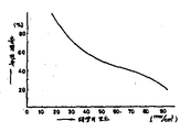
또한, 이때 표지의 윗면 면적은 약 50cm2로 그 중앙부에 약 30cm2의 수광 면적이 있는 태양전지 모듈(2)을 설치하였다.In addition, the solar cell module 2 having a light receiving area of about 30 cm 2 at the center of the top surface of the cover was about 50 cm 2 .
제4도-제6도에 나타낸 데이터는 어느 것이나 3월 21일 가까이의 쾌청한 날에 일본 시가껜(![]()
![]()
제4도는 투광성 커버(3)를 설치한 태양전지 모듈(A)과 단지 평면 형상으로 설치한 태양전지(B)의 출력전류의 변화를 나타낸다.4 shows a change in the output current of the solar cell module A provided with the transparent cover 3 and the solar cell B provided only in a planar shape.
가로축은 시간의 변화 즉, 일출로부터 일몰까지를 나타내며, 세로축은 출력전류를 나타낸다.The horizontal axis represents time change, that is, from sunrise to sunset, and the vertical axis represents output current.
이 결과, 그 투광성 커버(2)를 설치한 태양전지 모듈(A)은 태양의 위치, 고도에 의하지 않고 뛰어난 집광능력에 의해서 높은 출력전류를 얻는다는 것을 알 수 있다.As a result, it can be seen that the solar cell module A provided with the
제5도는 태양의 조도의 변화에 있어서의 각각의 태양전지(A)(B)의 출력전류를 나타낸다.5 shows the output current of each of the solar cells A and B in the change in the illuminance of the sun.
가로축은 태양의 조도를, 세로축은 출력전류를 각각 나타낸다.The horizontal axis represents the illuminance of the sun, and the vertical axis represents the output current.
그 결과, 태양전지 모듈(A)의 출력전류는 태양의 조도에 의하지 않고, 항상 태양전지 모듈(B)의 출력전류보다 15mA-25mA나 높은 전류가 얻어진다는 것을 알수 있다.As a result, it can be seen that the output current of the solar cell module A is always 15 mA-25 mA higher than the output current of the solar cell module B, regardless of the illuminance of the sun.
제6도는 단지 평면 형상으로 설치한 태양전지 모듈(B)의 출력전류에 대하여 투광성 커버(3)를 설치한 태양전지 모듈(A)의 출력전류의 증가율의 변화를 태양의 조도에 따라서 나타낸 것이다.FIG. 6 shows the change of the increase rate of the output current of the solar cell module A provided with the light-transmissive cover 3 with respect to the output current of the solar cell module B provided only in planar shape according to the illumination of the sun.
가로축은 태양의 조도를, 세로축은 태양전지 모듈(B)에 대한 태양전지 모듈(A)의 출력전류의 증가율을 각각 나타낸다.The horizontal axis represents the illuminance of the sun, and the vertical axis represents the increase rate of the output current of the solar cell module A with respect to the solar cell module B, respectively.
그 결과, 태양의 고도가 낮을때나 날씨가 불순할 경우 또는 장해물에 의하여 직사일광을 받기 어려운 장소 등의 낮은 조도시에는 태양전지 모듈(A)이 매우 뛰어난 출력특성이 있는 것을 발견하게 되었다.As a result, it has been found that the solar cell module A has excellent output characteristics in low illumination, such as when the sun is low, when the weather is impure, or where it is difficult to receive direct sunlight due to obstacles.
제4도-제6도에서 알 수 있는 바와 같이 표지(1)의 제한된 뒷면에 수광면이 둥그스름한 반타원구 형상의 투광성 커버(3)로 피복된 태양전지 모듈(2)을 설치하므로서 태양의 입사방향, 고도를 고려하지 않고 종래보다도 항상 높은 출력전류를 얻을 수 있고, 특히 태양고도가 낮은 시간대나 날씨가 흐린날 등의 태양의 낮은 조도에도 매우 뛰어난 출력전류를 얻을 수 있다.As can be seen from FIG. 4 to FIG. 6, the incident direction of the sun is provided on the limited back surface of the cover 1 by installing the
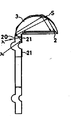
(b) 제7도와 같이 투광성 커버(3)의 앞부분을 표지면 위로 뻗어나오게 하여 투광성의 뻗어나온 부분(20)으로 하고 그 뻗어나온 부분(20)의 윗면에 빛의 반사층(21)을 형성해두면 그 커버(3)의 위에 눈이나 먼지가 쌓였을 때에도 또한 태양전지 모듈(2)을 작동할 수가 있다.(b) As shown in FIG. 7, the front portion of the transparent cover 3 extends over the cover surface to form a translucent stretched
즉 제8도와 같이 뻗어나온 부분(20)의 바깥면으로부터 입사(入射)된 주위의 태양광 γ는 뻗어나온 부분(20)의 두꺼운 안을 투과하여 뻗어나온 부분(20)의 뒷면에 형성된 반사층(21)에서 전반사(全反射)하고. 또한 그 두꺼운 안을 직진하여 뻗어나온 부분(20)의 표면 계면(界面)으로 재차 반사한다.That is, the surrounding solar light γ incident from the outer surface of the
즉, 뻗어나온 부분(20)의 두꺼운 안쪽에서 난(亂)반사를 일으켜서 결국은 뻗어나온 부분(20)의 바깥면으로부터 입사된 태양광이 투광성 커버(3)내로 전도된다.That is, the light is incident on the thick inner side of the extended
이로 인해서 예를 들면 태양전지 모듈(2)의 투광성 커버(3)의 수광면 위에 눈 (또는 먼지) (S)가 두껍게 쌓여서 태양광이 입사하지 않더라도 뻗어나온 부분(20)의 바깥면으로부터 입사한 태양광이 뻗어나온 부분(20)으로부터 투광성 커버(3)안으로 전도하여 태양전지 모듈(2)에서 출력전압이 얻어진다.As a result, for example, the snow (or dust) S is thickly accumulated on the light receiving surface of the transparent cover 3 of the
(II) 발광 다이오드(4)를 씌우는 투광성 커바(6)에 대하여 : 제9도와 같이 발광 다이오드(4)를 씌운 투광성 커버(6)중, 다이오드(4)의 발광부(40)의 상하부 및 인접한 발광부(40)사이의 뒷면쪽에 전술한 발광부(40)의 영역을 남겨서 빛의 반사층(22)을 형성해 두면 전류 소비가 적지만 광학적 지향성이 좁은 발광 다이오드의 점등광을 유효하게 이용하여 표지면 전면 또는 주요부분이 발광하고 있는 것 같이 보이므로 표지로서 더욱 알아보기 쉽게되어 교통사고 등을 미연에 방지할 수가 있다.(II) Translucent cover 6 covering the light emitting diode 4: Among the translucent covers 6 covering the light emitting diode 4 as shown in FIG. 9, the upper and lower portions of the
즉, 전술한 구성의 경우 제10도에 나타낸 바와 같이 발광 다이오드(4)에 전류가 흐르게 되면 전술한 투광성 커버(3)안에 돌출한 발광부(40)의 칩(발광점)으로부터 점등광이 발사된다.That is, in the case of the above-described configuration, when a current flows in the light emitting diode 4 as shown in FIG. 10, the lighting light is emitted from the chip (light emitting point) of the
예를 들면 칩에서 경사진 앞쪽으로 발사된 점등광 γ0는 커버(6)안을 직진하여 그 커버(6)의 표면 계면에서 점등광 γ0의 일부는 바깥쪽으로 투과(투과광 γ1)하고 그 나머지는 반사되여 재차 그 커버(6)안을 직진하는 1차 반사광 γ1은 그 커버(6)의 뒷면에 설치된 반사층(22)에서 전반사가 일어나서 전반사된 2차 반사광 γ2는 재차 그 커버(6)안을 직진하여 그 커버(6)의 표면 계면 투과(투과광 γ3) 및 반사(3차 반사광 γ3)가 일어난다.For example, the lighting light γ 0 emitted from the front of the chip goes straight inside the cover 6, and at the surface interface of the cover 6, a part of the lighting light γ 0 transmits outwardly (transmission light γ 1 ) and the rest of the lighting light γ 0 . Is reflected, and the primary reflected light γ 1 which is again traveling straight into the cover 6 is totally reflected in the
즉, 발광부(40)의 칩으로부터 발사된 모든 방향의 점등광은 적어도 그 발광부(40)의 윗부분 및 인접하는 발광부(40)사이의 영역을 씌운 커버(6)의 두꺼운 안에서 난반사를 하고, 그 결과 표지면의 커버(6)가 전면에 걸쳐서 발광하고 있는 것같이 보인다.That is, the lighting light in all directions emitted from the chip of the
그로 인하여 운전자가 알아보기 쉽게 대폭 개선된다.This greatly improves the driver's visibility.
이상과 같은 표지의 발전 형태는 따라서 본 발명 표지 및 본 발명 표지 구조체에 바람직하게 적용될 수 있다.The development form of the above label can thus be preferably applied to the label of the present invention and the label structure of the present invention.
Claims (9)
Applications Claiming Priority (2)
| Application Number | Priority Date | Filing Date | Title |
|---|---|---|---|
| JP19070 | 1985-01-31 | ||
| JP60019070A JPS61176709A (en) | 1985-01-31 | 1985-01-31 | Light self-emitting type delineator |
Publications (2)
| Publication Number | Publication Date |
|---|---|
| KR860006190A KR860006190A (en) | 1986-08-28 |
| KR900005748B1 true KR900005748B1 (en) | 1990-08-09 |
Family
ID=11989168
Family Applications (1)
| Application Number | Title | Priority Date | Filing Date |
|---|---|---|---|
| KR1019850007826A KR900005748B1 (en) | 1985-01-31 | 1985-10-23 | Cover and structure of light self emitting type |
Country Status (2)
| Country | Link |
|---|---|
| JP (1) | JPS61176709A (en) |
| KR (1) | KR900005748B1 (en) |
Cited By (3)
| Publication number | Priority date | Publication date | Assignee | Title |
|---|---|---|---|---|
| KR200455815Y1 (en) * | 2010-04-12 | 2011-09-27 | (주)성일솔레드 | Solar fog light |
| CN106012885A (en) * | 2016-06-23 | 2016-10-12 | 安庆市亿网科技有限公司 | Indication stake for public ground |
| CN106087789A (en) * | 2016-06-23 | 2016-11-09 | 安庆市亿网科技有限公司 | The instruction stake of a kind of curbside |
Families Citing this family (5)
| Publication number | Priority date | Publication date | Assignee | Title |
|---|---|---|---|---|
| JPS62174406A (en) * | 1986-01-28 | 1987-07-31 | 星和電機株式会社 | Power source built-in type spontaneous light guide mark |
| KR100668440B1 (en) * | 2005-05-21 | 2007-01-12 | 이대훈 | Hinge |
| JP5072783B2 (en) * | 2008-09-11 | 2012-11-14 | エムケー精工株式会社 | Gaze guidance system |
| JP2012046914A (en) * | 2010-08-25 | 2012-03-08 | Sekisui Jushi Co Ltd | Light emission display system for road |
| JP6145254B2 (en) * | 2012-07-13 | 2017-06-07 | 株式会社キャットアイ | Interlocking arrow display device and interlocking indicator light device |
-
1985
- 1985-01-31 JP JP60019070A patent/JPS61176709A/en active Granted
- 1985-10-23 KR KR1019850007826A patent/KR900005748B1/en not_active IP Right Cessation
Cited By (3)
| Publication number | Priority date | Publication date | Assignee | Title |
|---|---|---|---|---|
| KR200455815Y1 (en) * | 2010-04-12 | 2011-09-27 | (주)성일솔레드 | Solar fog light |
| CN106012885A (en) * | 2016-06-23 | 2016-10-12 | 安庆市亿网科技有限公司 | Indication stake for public ground |
| CN106087789A (en) * | 2016-06-23 | 2016-11-09 | 安庆市亿网科技有限公司 | The instruction stake of a kind of curbside |
Also Published As
| Publication number | Publication date |
|---|---|
| KR860006190A (en) | 1986-08-28 |
| JPS61176709A (en) | 1986-08-08 |
| JPH0534445B2 (en) | 1993-05-24 |
Similar Documents
| Publication | Publication Date | Title |
|---|---|---|
| US4841278A (en) | Self-illuminant delineator and delineator system by use thereof | |
| US4668120A (en) | Solar-powered illuminated reflector | |
| EP1481192B1 (en) | Marker lights for wireless doorbell transmitters and similar devices | |
| CN111566405B (en) | Low-height installation type low-power consumption intelligent street lamp system | |
| US20050046595A1 (en) | Solar powered sign annunciator | |
| JPWO2004095590A1 (en) | Self-luminous device | |
| KR100729910B1 (en) | Integrated solar delineator | |
| ES2311469T3 (en) | SOLAR POWERED APPARATUS. | |
| KR900005748B1 (en) | Cover and structure of light self emitting type | |
| US20110135386A1 (en) | Apparatus for indicating the formation of ice on a road | |
| KR100895722B1 (en) | Solar tubular markers | |
| KR101561810B1 (en) | Traffic sign board apparatus having solar cells of traffic sign shape | |
| KR101030282B1 (en) | Controller of load pilot lamp having a function of alteration color | |
| US20010055206A1 (en) | Lightning fixture for showing roadway diversion | |
| KR101499708B1 (en) | Road Marker | |
| JP3513745B2 (en) | Road tack | |
| KR200389207Y1 (en) | The center line indicator of road using solar-cell | |
| GB2449979A (en) | Indicating ice formation on a road | |
| KR101257663B1 (en) | Bus station safety system based on solar cell | |
| JP2002275839A (en) | Security display tool of internal light emission | |
| JPS63241207A (en) | Light self-emitting traffice control apparatus | |
| JP3250010B2 (en) | Self-luminous gaze guide | |
| JP2986158B1 (en) | Traffic sign equipment | |
| JP2915267B2 (en) | Light emitting device with solar cell | |
| JPH0421190Y2 (en) |
Legal Events
| Date | Code | Title | Description |
|---|---|---|---|
| A201 | Request for examination | ||
| E902 | Notification of reason for refusal | ||
| G160 | Decision to publish patent application | ||
| E701 | Decision to grant or registration of patent right | ||
| GRNT | Written decision to grant | ||
| FPAY | Annual fee payment |
Payment date: 19990702 Year of fee payment: 10 |
|
| LAPS | Lapse due to unpaid annual fee |