KR900004869B1 - Operation control method for nucelar reactor - Google Patents
Operation control method for nucelar reactor Download PDFInfo
- Publication number
- KR900004869B1 KR900004869B1 KR1019840001599A KR840001599A KR900004869B1 KR 900004869 B1 KR900004869 B1 KR 900004869B1 KR 1019840001599 A KR1019840001599 A KR 1019840001599A KR 840001599 A KR840001599 A KR 840001599A KR 900004869 B1 KR900004869 B1 KR 900004869B1
- Authority
- KR
- South Korea
- Prior art keywords
- reactivity
- reactor
- control
- output
- liquid poison
- Prior art date
Links
Images


Classifications
-
- G—PHYSICS
- G21—NUCLEAR PHYSICS; NUCLEAR ENGINEERING
- G21C—NUCLEAR REACTORS
- G21C7/00—Control of nuclear reaction
-
- G—PHYSICS
- G21—NUCLEAR PHYSICS; NUCLEAR ENGINEERING
- G21C—NUCLEAR REACTORS
- G21C7/00—Control of nuclear reaction
- G21C7/36—Control circuits
-
- Y—GENERAL TAGGING OF NEW TECHNOLOGICAL DEVELOPMENTS; GENERAL TAGGING OF CROSS-SECTIONAL TECHNOLOGIES SPANNING OVER SEVERAL SECTIONS OF THE IPC; TECHNICAL SUBJECTS COVERED BY FORMER USPC CROSS-REFERENCE ART COLLECTIONS [XRACs] AND DIGESTS
- Y02—TECHNOLOGIES OR APPLICATIONS FOR MITIGATION OR ADAPTATION AGAINST CLIMATE CHANGE
- Y02E—REDUCTION OF GREENHOUSE GAS [GHG] EMISSIONS, RELATED TO ENERGY GENERATION, TRANSMISSION OR DISTRIBUTION
- Y02E30/00—Energy generation of nuclear origin
- Y02E30/30—Nuclear fission reactors
Abstract
Description
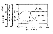
제1도는 부하추종운전을 실시했을 때의 압력관형 원자로에 있어서의 제특성의 변화를 나타낸 설명도.1 is an explanatory diagram showing changes in various characteristics in a pressure tube reactor when a load following operation is performed.
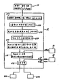
제2도는 압력관형 원자로에 적용한 본원 발명의 적합한 일실시예인 부하추종 제어장치의 계통도.2 is a schematic diagram of a load follower control device according to one preferred embodiment of the present invention applied to a pressure tube reactor.
제3도는 제2도에 Ⅱ-Ⅱ 단면도.3 is a II-II cross-sectional view of FIG.
제4도는 제2도에 나타낸 부하추종 제어장치의 상세 계통도.4 is a detailed schematic diagram of the load tracking control device shown in FIG.
제5도는 부하변경계획의 설명도.5 is an explanatory diagram of a load change plan.
제6도는 제4도에 나타낸 제어봉 제어장치의 기능을 나타낸 구조도.6 is a structural diagram showing the function of the control rod control device shown in FIG.
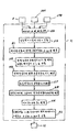
제7도는 제4도에 나타낸 액체포이즌 제거·주입속도 수정장치의 기능을 나타낸 플로차트.FIG. 7 is a flowchart showing the function of the liquid poison removal and injection speed correction device shown in FIG.
제8도는 제4도에 나타낸 제어봉위치 수정장치의 기능을 나타낸 플로차트.8 is a flowchart showing the function of the control rod position correction device shown in FIG.
제9도는 제4도에 나타낸 액체포이즌 제거·주입속도 결정장치의 기능을 나타낸 플로차트.9 is a flowchart showing the function of the liquid poison removal and injection speed determination device shown in FIG.
제10도는 크세논 및 사마륨동적특성을 나타낸 설명도.10 is an explanatory diagram showing xenon and samarium dynamic properties.
제11도는 노심반응도변화를 나타낸 특성도.11 is a characteristic diagram showing the change in core reactivity.
제12도는 필요제어반응도 변화를 나타낸 특성도.12 is a characteristic diagram showing a change in required control responsiveness.
제13도는 제어시간구분의 결정을 나타낸 설명도.13 is an explanatory diagram showing determination of control time classification.
제14도는 중수(重水)중의 액체포이즌 농도와 반응도와의 관계를 나타낸 특성도.14 is a characteristic diagram showing the relationship between the liquid poison concentration in heavy water and the reactivity.
제15도는 액체포이즌 제거·주입기준속도의 특성도.15 is a characteristic diagram of the liquid poison removal / injection reference speed.
제16도는 제2도에 나타낸 투입반응도 계산장치(31)의 기능을 나타낸 플로차트.FIG. 16 is a flowchart showing the function of the input
제17도는 제어봉위치와 투입반응도와의 관계를 나타낸 특성도.Figure 17 is a characteristic diagram showing the relationship between the control rod position and the input reactivity.
제18도는 액체포이즌 제거·주입조작시간과 투입반응도와의 관계를 나타낸 특성도.18 is a characteristic diagram showing the relationship between the liquid poison removal and injection operation time and the input reactivity.
제19도는 제2도에 나타낸 액체포이즌 제거·주입속도 지시장치의 기능을 나타낸 플로차트.FIG. 19 is a flowchart showing the function of the liquid poison removal and injection speed indicating device shown in FIG.
제20도는 가압수형 원자로에 적용한 본원 발명의 다른 실시예의 계통도.20 is a schematic diagram of another embodiment of the present invention applied to a pressurized water reactor.
본원 발명은 원자로의 운전제어방법에 관한 것이며, 특히 제어봉 및 액체포이즌(poison)을 사용하여 출력제어를 행하는 원자로의 일부하(日負荷) 추종운전에 적용할 수 있는 원자로의 운전제어 방법에 관한 것이다.The present invention relates to a method for controlling the operation of a nuclear reactor, and more particularly, to a method for controlling the operation of a nuclear reactor that can be applied to a partial load following operation of a nuclear reactor that performs output control using a control rod and a liquid poison. .
압력관형(壓力管型) 원자로는 연료집합체를 내장하는 다수의 압력관을 감속재가 충전된 가열유체탱크에 그것을 관통하여 설치한 것이다. 압력관내는 냉각제가 유동한다. 이와 같은 압력관형 원자로의 출력제어는 가열유체탱크내에서 압력관 사이에 삽압되는 제어봉의 출입조작과, 가열유체탱크내의 감속재중에 혼입되는 액체포이즌 농도의 조절에 의해 행해진다.Pressure tube reactors are a plurality of pressure tubes containing fuel assemblies penetrated through a heating fluid tank filled with moderators. The coolant flows in the pressure tube. Such output control of the pressure tube reactor is performed by the operation of the control rod inserted and inserted between the pressure tubes in the heating fluid tank and the adjustment of the concentration of the liquid poison mixed in the moderator in the heating fluid tank.
최근, 원자로의 운전방법으로서는 베이스로드용으로서의 고정된 출력운전뿐만 아니라 부하의 변동에 따라서 출력을 변화시키는 부하추종운전의 적용이 검토되기 시작하고 있다. 상술한 압력관형 원자로도 예외는 아니며, 부하추종운전을 적용하는 것이 검토되고 있다. 그 구체예로서 일본국 특개소 57-141594호 공보에 나타낸 것이 이미 제안되어 있다.Recently, as a method of operating a reactor, application of not only a fixed output operation for the base load but also a load following operation in which the output is changed in accordance with the change of the load is being considered. The above-described pressure tube reactor is not an exception, and application of load following operation is under consideration. As the specific example, what was shown by Unexamined-Japanese-Patent No. 57-141594 is already proposed.
상기 공개공보의 제5도에 나타낸 압력관형 원자로의 부하추종 운전제어장치는 하루의 주간과 야간의 전력 수요에 대응시켜, 매일 주간의 원자로 출력을 높게 하고, 야간의 원자로 출력을 낮게 제어하는 것이다. 압력관형 원자로와 같이 제어수단으로서 제어봉 및 액체포이즌 농도조절을 사용하는 원자로(압력관형 원자로 이외에 가압수형(加壓水型) 원자로가 있음)에서는 원자로 출력의 하강(또는 상승은 소정의 하강률 또는 상승률)에서 설정된 출력하강선(또는 출력상승선)을 중심으로 상하에 허용폭을 갖게 하여 이루어진 허용출력 하안선과의 범위내에서 행해진다.The load follower operation control apparatus for the pressure tube reactor shown in FIG. 5 of the above publication responds to the power demand of the day and the night, thereby increasing the daily reactor output and controlling the reactor output at night. In reactors that use control rods and liquid poison concentration control as control means, such as pressure tube reactors (pressurized water reactors in addition to pressure tube reactors), the reactor output drop (or rise is a predetermined rate of descent or rise). It is carried out within the range of the allowable output lower line formed by allowing the upper and lower allowable widths centering on the output lowering line (or output rising line) set in ().
압력관형 원자로의 부하추종운전제어에 대해 다음에 설명한다.The load follow operation control of the pressure tube reactor is described next.
가열유체탱크내의 액체포이즌의 농도를 증가시킴으로써 주간의 높은 원자로 출력에서 야간의 낮은 원자로 출력으로 낮춘다. 제어봉의 삽입, 인발 등의 조작은 급격한 출력변동에 의해 연료집합체에 주는 손상이 크므로, 원자로 출력이 허용출력의 상한 또는 하한선을 일탈하는 경우에만 실시된다. 제어봉 조작은 액체포이즌 농도의 조절에 비해 원자로 출력의 변동비율이 매우 크며, 원자로 출력의 고출력 영역에서의 그 조작은 연료집합체에 손상을 줄 위험성이 있다. 이 때문에, 고출력 영역에서의 제어봉의 조작은 되도록 억제하는 것이 바람직하다.Increasing the concentration of liquid poisons in the heating fluid tank lowers from daytime high reactor power to nighttime low reactor power. Insertion, drawing, etc. of the control rod are largely damaged to the fuel assembly due to sudden power fluctuations, and thus are only performed when the reactor output deviates from the upper or lower limit of the allowable output. Control rod operation has a very high rate of change in reactor output compared to control of liquid poison concentration, and the operation in the high power region of the reactor output risks damage to the fuel assembly. For this reason, it is preferable to suppress operation of the control rod in high output area | region as much as possible.
상술한 공개공보의 제5도에 나타낸 압력관형 원자로의 부하추종 운전제어는 부하추종운전시의 제어봉 조작의 회수를 저감시키려고 하는 것이다. 이 부하추종운전제어는 원자로 출력의 설정치 및 원자로의 동적(動的) 특성 해석용 데이터를 사용하여 원자로출력 변화에서 반응도의 시간변화의 예측치를 구하고, 예측치에서 구한 반응도 변화율의 크기에 따라서 출력제어의 시간을 구분하고, 각 구분시간내에 있어서의 액체포이즌의 주입량 또는 제거량의 최적치를 구하고, 가열유체탱크내의 액체포이즌 농도를 최적치로 조정하는 것이다. 그러나, 이 방법에 있어서도 제어봉의 조작회수는 감소 되었다고는 하나 원자로 출력을 50%로 하는 부하추종운전을 실시했을 경우, 원자로 출력을 50%로 유지하는 전후의 제어봉의 조작회수는 약 300회에 이른다.The load following operation control of the pressure tube reactor shown in FIG. 5 of the above-mentioned publication is intended to reduce the number of control rod operations during the load following operation. This load follow-up operation control calculates the predicted value of the time change of responsiveness from the change of reactor output by using the set value of the reactor output and the data for analyzing the dynamic characteristics of the reactor. The time is divided, the optimum value of the injection amount or removal amount of the liquid poison within each division time is obtained, and the concentration of the liquid poison in the heating fluid tank is adjusted to the optimum value. However, even in this method, although the number of times of operation of the control rod is reduced, when the load tracking operation is performed at 50% of the reactor output, the number of times of operation of the control rod before and after maintaining the reactor output at 50% is about 300 times. .
본원 발명의 목적은 반복하여 실시되는 부하추종운전제어를 단순화 할 수 있는 원자로의 운전제어방법을 제공하는데 있다.An object of the present invention is to provide a method for controlling the operation of a nuclear reactor that can simplify the load following operation control repeatedly performed.
본원 발명의 다른 목적은 원자로 출력의 조조정용(祖調整用) 제어수단의 조작회수를 저감할 수 있는 원자로의 운전제어방법을 제공하는 데 있다.Another object of the present invention is to provide a method for controlling the operation of a reactor that can reduce the number of operations of control means for adjusting the output of the reactor.
본원 발명에 의하면, 원자로 출력의 조조정용으로서 제어봉으로 구성되는 제1제어수단과, 원자로 출력의 미조정용으로서 액체포이즌농도 조절수단으로 구성되는 제2제어수단을 갖는 원자로의 출력을 종전의 부하변경계획과는 상이하며, 소정 기간내의 부하변경이 주기적으로 반복되는 일정한 부하변경계획에 의거하여 예측되는 반응도에 따라서 제어하는 원자로의 운전제어방법에 있어서, 상기 부하변경계획의 제1 사이클에 있어서 상기 제1 제어수단의 조작에 의해 투입된 제1 반응도를 구하고, 상기 제1 사이클에 있어서의 상기 제2 제어수단의 조작에 의해 투입된 제2 반응도를 구하고, 상기 제1 사이클에 연속하는 부하변경계획의 제2 사이클에 있어서 상기 제2 제어수단의 조작에 의해 설정될 제3 반응도를 제1 및 제2 반응도에 따라서 예측하며, 상기 제3 반응도를 상기 제1 사이클기간에 예측하여 값을 기억하고, 상기 제2 사이클동안 상기 제1 사이클기간에 기억된 제3 반응도에 따라서 상기 제2 사이클에 있어서의 상기 제2 제어수단을 작동시킴으로써 원자로 출력을 제어하는 것을 특징으로 하는 원자로의 운전제어 방법을 제공한다.According to the present invention, the load change plan of the reactor having the first control means composed of control rods for adjustment of the reactor output and the second control means composed of liquid poison concentration adjustment means for fine adjustment of the reactor output is known. A method of operating a reactor for controlling a reactor according to a reactivity predicted on the basis of a constant load change plan in which load change within a predetermined period is repeated periodically, the first cycle in the first cycle of the load change plan; Obtaining the first reactivity introduced by the operation of the control means, obtaining the second reactivity introduced by the operation of the second control means in the first cycle, and the second cycle of the load change plan following the first cycle. Predicting the third reactivity to be set by the operation of the second control means according to the first and second reactivity and By predicting a third reactivity in the first cycle period and storing a value, and operating the second control means in the second cycle according to the third reactivity stored in the first cycle period during the second cycle. A reactor control method for controlling a reactor output is provided.
이와 같은 본원 발명의 특징에 의하면, 종전의 사이클기간의 반응도에 의거하여 다음 사이클기간의 제2 제어수단의 조작을 행하여 원자로 출력을 제어하고 있으므로, 부하추종운전의 제어가 단순화되고, 매우 용이해진다.According to this aspect of the present invention, since the reactor output is controlled by operating the second control means in the next cycle period based on the reactivity of the previous cycle period, the control of the load following operation is simplified and becomes very easy.
압력관형 원자로에 부하추종운전을 적용했을 경우, 부하변경계획이 매일 같은 패턴 즉 부하변동사이클로 반복되면, 2일째 이후의 노심(爐心) 반응도 변화의 패턴이 실질적으로 동일해진다고 하는 것을 알았다. 그 현상을 다음에 설명한다. 제1도는 매일 부하를 변경하는 부하추종운전을 행했을 경우의 압력관형 원자로의 노심반응도 변화를 나타내고 있다. 이 경우에 있어서의 부하추종운전의 부하변경계획(37A)은 100%의 전기출력을 특성1(실선)으로 나타낸 것처럼 1시간 50%까지 낮추어, 50% 전기출력을 8시간 유지하고, 그 시간 경과 후에 1시간에 전기출력을 50%에서 100%까지 상승시켜, 전기출력 100%를 14시간 유지한다고 하는 패턴(부하변동사이클)을 매일 반복하는 것이다. 이와 같은 부하변경계획(37A)에 의거한 부하추종운전이 실시되기까지는 압력관형 원자로는 전기출력 100%를 얻도록 운전되고 있었던 것으로 한다. 특성 1과 같이 전기출력이 변화하면 그것에 수반해서 원자로의 열출력은 특성2(파선)과 같이 (55%로부터 100%), 또 노심내에서 핵분열에 의해 발생하는 크세논의 농도는 특성3(1점쇄선)과 같이 변화한다. 특성1과 같이 전기출력을 변경할 경우, 노심반응도는 특성3의 크세논 농도의 변화 및 출력계수의 영향을 받아 특성4(2점쇄선)와 같이 변화한다. 특성4의 노심반응도는 원자로의 운전형태를 바꾼 1일째는 별도로 하고, 2일째 이후에서 실질적으로 같은 변화로 되어 있다.When the load follower operation was applied to the pressure tubular reactor, it was found that if the load change plan was repeated in the same pattern every day, that is, in the load fluctuation cycle, the core responsiveness change pattern after the second day was substantially the same. The phenomenon is described next. FIG. 1 shows the change in the core reactivity of the pressure tube reactor when the load following operation is performed in which the load is changed every day. In this case, the load change plan 37A of the load following operation lowers the electric output of 100% to 50% for 1 hour as indicated by the characteristic 1 (solid line), maintains the 50% electrical output for 8 hours, and then elapses the time. Afterwards, the electric power is increased from 50% to 100% in 1 hour, and the pattern (load fluctuation cycle) is repeated every day to maintain 100% of electric power for 14 hours. It is assumed that the pressure tube reactor was operated so as to obtain an electrical output of 100% until the load tracking operation based on the load change plan 37A. When the electrical output changes as in
이와 같은 경향은 고전기출력 100%, 저전기출력 50%의 부하추종운전패턴에서 고전기출력 100%, 저전기출력 70%의 상이한 부하추종운전패턴으로 바꾸었을 경우도 같다. 즉, 후자의 패턴을 반복하여 부하추종운전을 실시함으로써, 패턴변화 후 2일째 이후의 노심반응도의 변화는 실질적으로 같다.This tendency is also the case when the load tracking operation pattern of 100% of high electric power output and 50% of low electric power output is changed to the different load tracking operation patterns of
본원 발명은 같은 패턴의 부하추종운전을 반복하여 실시할 경우, 그 패턴을 몇번인가 반복한 다음에는 노심반응도의 변화가 실질적으로 같다고 하는 현상을 이용한 것이다.In the present invention, when the load following operation of the same pattern is repeatedly performed, the phenomenon that the change in core reactivity is substantially the same after repeating the pattern several times is used.
본원 발명의 적합한 일실시예인 원자로의 부하추종운전제어방법을 제2도에 의거하여 설명한다. 제2도는 압력관형 원자로에 적용한 부하추종제어장치를 나타내고 있다. 압력관형 원자로는 내부에 감속재인 중수가 충전되어 있는 가열유체탱크(1) 및 가열유체탱크(1)에 관통시켜 부착하여 연료집합체(3)를 내장하는 압력관(2)을 가지고 있다. 압력관(2)의 가열유체탱크(1)의 수평단면에 있어서의 베치는 제3도에 나타낸다. 냉각재인 경수(輕水)(단지 냉각수라고 함)는 압력관(2)의 하부에서 압력관(2)내에 공급되며, 연료집합체(3)에 의해 가열되어 증기로 된다. 증기를 포함하고 있는 냉각수는 압력관(2)의 상부에서 증기드럼(도시생략)내에 공급된다. 여기서, 증기는 분리되어 터빈(도시생략)에 보낸다. 냉각수는 증기 드럼에 공급되는 급수와 함께 압력관(2)하부에 다시 인도된다. 냉각재로서 중수를 사용하는 압력관형 원자로도 있다. 이 경우, 압력관(2)에서 토출된 중수는 증기발생기에서 경수와 열교환되어 다시 압력관(2)내로 귀환한다. 경수는 증기발생기에서 증기로 되어 터빈으로 귀환한다. 가열유체탱크(1)내의 감속재인 중수는 순화펌프(4)의 구동에 의해 중수 순환배관(5) 및 가열유체탱크(1)내를 순환한다.A preferred method of controlling the load following operation of a nuclear reactor according to the present invention will be described with reference to FIG. 2 shows a load tracking control device applied to a pressure tube reactor. The pressure tubular reactor has a heating fluid tank (1) filled with heavy water, which is a moderator, and a pressure pipe (2) which penetrates and attaches the heating fluid tank (1) to embed the fuel assembly (3). Bets in the horizontal section of the
압력관형 원자로의 원자로출력은 가열유체탱크(1)의 압력관(2)의 사이, 즉 연료집합체(3) 사이에 출입되는 출력조정용의 제어봉(스테인레스봉)(6)의 조작 및 가열유체탱크(1)내에 충전되어 있는 중수중에 포함되는 액체포이즌 농도의 조절에 의해 제어된다. 제1 제어수단을 구성하는 제어봉(6)은 제어봉 구동장치(7)에 연결되며, 제어봉 구동장치(7)에 의해 다수의 연료집합체(3)로 구성되는 노심에 삽입되거나 또는 그것에서 인발된다. 출력조정용의 제어봉(6) 이외에 원자로의 운전을 정지시키는 운전정지용의 제어봉(도시생략)이 다수 설치되어 있다. 운전정지용의 제어봉은 원자로의 통상 운전시에 노심에서 인발되어 있으며, 정지시에 노심에 삽입된다. 액체포이즌농도의 조절은 제2 제어수단을 구성하는 액체포이즌 주입장치(9) 및 액체포이즌 제거장치(16)로 구성되는 액체포이즌 농도조절수단의 조작으로 행해진다. 액체포이즌 주입장치(9) 및 액체포이즌 제거장치(16)는 중수순환배관(5)에 부착된다. 액체포이즌 주입장치(9)는 중수순환배관(5)에 접속되는 배관(10), 배관(10)에 접속되어 내부에 액체포이즌이 충전된 액체포이즌 탱크(11), 배관(10)에 부착되는 스톱밸브(12) 및 유량조절밸브(13)로 구성된다. 액체포이즌 농도계(14) 및 유량계(15)가 배관(10)에 배설된다. 액체포이즌 제거장치(16)는 양단이 중수순환배관(5)에 접속되는 배관(17), 배관(17)에 부착되어 내부에 이온교환수지가 충전된 액체포이즌 제거탑(18), 배관(17)에 설치된 스톱밸브(19) 및 (20)으로 이루어져 있다. 유량계(21)가 배관(17)에 배설된다. 유량조절밸브(22)는 중수순환배관(5)에 배치되어, 액체포이즌 제거장치(16)가 기능하고 있지 않을 때, 즉 스톱밸브(19) 및 (20)이 닫혀 있을 때에는 전개(全開)의 상태에 있다. 액체포이즌 제거장치(16)가 기능하고 있을 때, 즉 스톱밸브(19) 및 (20)이 열려 있을 때, 유량조절밸브(22)의 개폐도가 감소되어 중수순환배관(5)에서 액체포이즌 제거탑(18)에 공급되는 중수 유량이 제어된다.The reactor output of the pressure tubular reactor is operated by the control rod (stainless steel rod) 6 for adjusting the power input and output between the
제어봉(6), 액체포이즌 주입장치(9) 및 액체포이즌 제거장치(16)의 조작은 가열유체탱크(1)내에서 압력관(2) 사이에 중성자 검출기(23)의 출력에 의거하여 제어된다.The operation of the control rod 6, the liquid poison injection device 9 and the liquid poison removal device 16 is controlled based on the output of the
이와 같은 압력관형 원자로의 부하추종제어장치는 부하추종제어장치(24), 액체포이즌 제거제어장치(29A), 액체포이즌 주입제어장치(29B), 일정부하추종제어장치(30), 원자로 출력통괄제어장치(33) 및 조작반(34)으로 이루어져 있다. 조작반(34)을 제외한 다른 제어장치는 전자계산기로 구성된다. 원자로 출력통괄제어장치(33)는 부하추종제어장치(24) 및 일종부하추종제어장치(30)를 통괄하고 있다.Such a load follower control device for a pressure vessel reactor includes a load
비교적 장시간의 커다란 반응도의 제어에는 중수중의 액체포이즌 농도의 조절의 적합하며, 단시간에서의 반응도의 조정에는 제어봉(6)의 조작이 적합하다. 그러나, 원자로 출력이 높은 영역에 있어서의 제어봉(6)의 조작은 연료파손의 위험성을 저감시키는 관점에서 되도록 피하는 것이 바람직하다. 제2 제어수단을 구성하는 액체포이즌 농도조절수단은 지효성(遲效性) 제어수단인 동시에 원자로 출력 미조정용 제어수단이다. 제1 제어수단을 구성하는 제어봉(6)은 즉효성(卽效性) 제어수단인 동시에 액체포이즌 농도조절수단에 비해 원자로 출력을 크게 변동시키므로 원자로 출력 조조정용 제어수단이라고 할 수 있다. 본 실시예는 부하추종운전을 되도록 액체포이즌 농도의 조절을 실시함으로써 달성하고자 하는 것이다.The control of the concentration of the liquid poison in heavy water is suitable for the control of large reactivity for a relatively long time, and the operation of the control rod 6 is suitable for the adjustment of the reactivity in a short time. However, it is preferable to avoid the operation of the control rod 6 in a region where the reactor output is high from the viewpoint of reducing the risk of fuel damage. The liquid poison concentration adjusting means constituting the second control means is both a slow control means and a control means for fine-tuning the reactor output. The control rod 6 constituting the first control means can be said to be a control means for adjusting the reactor output, since it is an immediate control means and changes the reactor output significantly compared with the liquid poison concentration adjusting means. This embodiment is intended to achieve by adjusting the liquid poison concentration so as to perform the load following operation.
부하추종제어장치(24)는 제4도에 나타낸 것처럼 제어봉 제어장치(25), 액체포이즌 제거·주입속도수정장치(26), 액체포이즌 제거·주입속도결정장치(27) 및 제어봉위치수정장치(28)로 이루어져 있다. 일정부하추종제어장치(30)는 제2도에 나타낸 것처럼 투입반응도 계산장치(31) 및 액체포이즌 제거·주입속도지시장치(32)를 가지고 있다.The load
상기 제어장치를 사용하여 제1도의 특성(전기출력)에서 나타낸 부하변경계획(37A)를 실시하는 본 실시예의 부하추종운전제어방법을 다음에 상세히 설명한다. 제5도에 나타낸 부하변경계획(37B)은 제1도의 특성 1에 나타낸 전기출력에 의한 부하변경계획(37A)을 원자로 열출력의 변화로 나타낸 것이다. 즉, 부하변경계획(37A)와 부하변경계획(37B)은 동일한 것이다. 부하변경계획(37B)는 원자로 열출력(이하 단지 원자로 출력이라고 함)을 100%로부터 1시간에 55%까지 낮추고, 55%원자로 출력을 8시간 유지하며, 그후 1시간에 원자로 출력을 55%로부터 100%까지 상승시키고, 100%로 14시간 유지하는 것이다. 이 운전패턴은 조작반(34)에서 해제의 지령이 나오기까지 매일 반복된다. 원자로 출력이 55%일 때에 전기출력이 50%까지 내려가는 것은 원자로 출력이 낮아지면 터빈효율이 저아되기 때문이다. 제5도의 파선(38) 및 (39)는 부하변경계획(37B)의 상한치 및 하한치를 나타내고 있다. 압력관형 원자로는 출력제어할 때, 크세논의 농도변화의 영향을 받기 쉽고, 원자로 출력이 변동되기 쉽다. 이 변동을 억제하여 원자로의 출력제어를 용이하게 하기 위해 상한치(38) 및 하한치(39)가 설치되어 있다. 부하변경계획(37B)과 상한치(38) 및 하한치(39)와의 각 출력차 △P는 출력허용폭을 나타내고 있다.The load following operation control method of this embodiment in which the load change plan 37A shown in the characteristics (electrical output) of FIG. The load change plan 37B shown in FIG. 5 shows the load change plan 37A by the electric output shown in the
부하변경계획(37A)은 조작반(34)에서 원자로 출력통괄제어장치(33)에 입력되며, 그 메모리(도시생략)내에 기억된다. 출력허용폭 △P은 미리 원자로 출력통괄제어장치(33)의 메모리내에 기억되어 있다. 원자로 출력통과제어장치(33)는 원자로의 운전계획을 비교하여, 지금까지 실시하고 있던 원자로의 운전계획과 상이한 운전계획이 입력되면, 개폐기(35)를 닫는다. 원자로 출력통괄제어장치(33)는 부하변경계획(37A)에 의거하여 시간 t에 대응하는 전기출력 Pe(t)을 원자로 출력 Pn(t)으로 변환되고, 이 원자로 출력 Ph(t)을 개폐기(35)를 통해 순차 부하추종제어장치(24)에 전달한다. 즉, 원자로 출력통괄제어장치(33)는 부하변경계획(37A)(제1도)을 부하변경계획(37B)(제5도)으로 변환하여 출력한다. 시간 t은 원자로 출력통괄제어장치(33)에 내장되는 타이머기능에 의해 계측된다. 출력허용폭 △P 및 시간 t도 원자로 출력통괄제어장치(33)에서 부하추종제어장치(24)에 전달된다..The load change plan 37A is input from the
이들 신호를 입력하는 부하추종제어장치(24)의 기능을 설명한다.The function of the load
부하추종제어장치(24)의 제어봉제어장치(25)의 동작을 제6도에 의거하여 설명한다. 중성자검출기(23)의 출력신호 ø1(t)가 제어봉제어장치(25)에 입력된다. 제어봉제어장치(25)의 블록(25A)은 노심의 제어영역 i마다의 출력신호 ø1(t)에 의거하여 제어영역 i의 원자로 출력 Phi(t)을 구한다. 블록(25A)의 출력인 Phi(t)는 블록(25B)에 입력된다. 여기서 모든 제어영역 i의 원자로 출력 Ph(t)을 합계함으로서 원자로 출력 Pht(t)이 구해진다. 원자로 출력 Pht(t)은 블록(25C)에 입력되며, (1)식의 조건이 만족되는지 여부가 비교된다.The operation of the control
![]()
![]()
(1)식의 조건이 만족될 경우, 제어봉 구동장치(7)는 동작하지 않으며, 제어봉(6)은 움직이지 않는다. (1)식의 조건이 만족되지 않을 때, 즉 Pht(t)가 (Ph(t)-△P)보다도 작을 경우는 제어봉 인발신호가, 또 Pht(t)가 (Ph(t)+△P)보다도 클 경우는 제어봉 삽입신호가 블록(25C)에서 출력된다. 이들 제어봉 조작신호가 출력되고, 블록(25D)에서 조작해야 할 제어봉 구동장치(7)가 선택된다. 선택된 제어봉 구동장치(7)에 블록(25D)의 출력신호가 입력되면, 그것에 연결된 제어봉(6)이 (1)식을 만족하기까지 노심에서 인발된다(또는 삽입된다). 제어봉 구동장치(7)의 제어봉 위치검출기(8)의 출력인 위치신호 HCR(t)는 블록(25E)에 전달된다. 여기서, HCR(t)는 제어봉(6) 선단위 위치이다. 블록(25E)는 HCR(t)가 다음 식의 조건을 만족하는지 여부를 판단한다.When the condition of the expression (1) is satisfied, the control
![]()
![]()
여기서, HCRO은 제어봉(6)의 초기위치 및 △h는 제어봉(6)의 허용이동범위를 나타내고 있다. (HCRO-△h)는 제어봉(6)의 허용하한위치, (HCRO+△h)는 제어봉(6)의 허용상한위치를 각각 나타내고 있다. 위치신호 HCR(t)가 (2)식의 조건을 만족하지 않을 때, 블록(25E)의 출력신호에 의해 개폐기(25F)가 닫힌다. (2)식의 조건이 만족되어 있을 때, 개폐기(25F)는 열려있다. 개폐기(25F)가 닫히면, (2)식의 조건을 만족시키지 않는 위치신호 HCR(t)가 제어봉 위치수정장치(28)에 전달된다. 또, 제어봉 위치검출기(8)의 출력의 위치신호 HCR(t)는 액체포이즌 제거·주입속도수정장치(26)에 전달된다.Here, H CRO represents the initial position of the control rod 6 and Δh represents the allowable moving range of the control rod 6. (H CRO -Δh ) indicates the lower limit position of the control rod 6 and (H CRO + Δh) indicates the upper limit position of the control rod 6. When the position signal H CR (t) does not satisfy the condition of Expression (2), the
액체포이즌 제거·주입속도수정장치(26)의 기능을 제7도에 의거하여 설명한다. 액체포이즌 제거·주입속도수정장치(26)는 원자로 출력통과제어장치(33)에서 부하변경계획(37B)을 입력한다. 액체포이즌 제거·주입속도수정장치(26)는 후술하는 제어시간구분보다 매우 짧은 편차평균시간(예를들면 5분)내에 있어서의 제어봉(6) 조작에 의한 투입반응도(제어반응도의 예측치와 부하변경을 개시한 다음의 제어반응도의 실측치와의 차)에 대응하는 액체포이즌 제거·주입속도를 구하고, 이것에 의거하여 다음의 평균시간내에 있어서의 액체포이즌 제거·주입속도를 수정하는 것이다. 편차평균시간은 액체포이즌 제거·주입속도수정장치(26)내에 기억되어 있다. 스텝(26A)에서 편차평균시간 △t이 경과했는지 여부를 판정한다. 편차평균시간 △t이 경과했을 때, 제어봉 제어장치(25)에서 입력한 제어봉(6)의 위치신호 HCR(t)를 기억한다(스텝 26B). 새로운 편차평균시간이 경과한 시점의 위치신호 HCR(t)를 H1, 시간 △t전에 기억한 HCR(t)를 H0라고 한다. 즉, H1및 H0는 노심축방향에 있어서 제어봉(6)의 하단이 위치하는 레벨이다. 편차평균시간 △t내에 있어서의 제어봉(6)의 조작에 의한 투입반응도 △KC를 다음 식으로 구한다(스텝 26C). 여기서, L은 노심내에서의 제어봉(6)의 이동거리, α는 제어봉(6)의 단위길이 이동시에 있어서의 반응도이다.The function of the liquid poison removal and injection
![]()
![]()
다음에, 제어봉 투입반응도 △KC를 등가의 반응도를 얻는 액체포이즌농도 △P(시간 △t내에서의 액체포이즌 농도의 변화량)로 환산한다(스텝26D).Subsequently, the control rod input reaction degree ΔKC is converted into the liquid poison concentration ΔP (change amount of the liquid poison concentration within the time Δt) to obtain an equivalent reaction degree (Step 26D).
![]()
![]()
여기서, β는 액체포이즌의 단위농도당 반응도이다. 액체포이즌 농도 △P에 의거하여, 다음의 편차평균시간 △t내에 있어서의 액체포이즌 제거·주입속도의 수정분 △VCR을 다음 식에서 구한다(스텝 26E).Where β is the reactivity per unit concentration of the liquid poison. Based on the liquid poison concentration ΔP, the correction amount ΔV CR of the liquid poison removal / injection rate in the next deviation average time Δt is obtained from the following equation (
![]()
![]()
시간 △t전에 기억한 △VCR의 값 대신에 스텝(26E)에서 구한 새로운 수정분 △VCR을 스텝(26F)에서 기억한다. 이 수정분 △VCR의 값은 다음회 이후의 편차평균시간이 경과하고, 또한 제어봉(6)의 조작이 실시되기까지 액체포이즌 제거·주입속도수정장치(26)에서 액체포이즌 제거·주입속도결정장치(27)에 출력된다.Instead of the value of? V CR stored before the time? T, the new correction? V CR obtained in
제어봉 위치수정장치(28)는 제어봉(6)의 위치를 소정 범위내에 두려고 하는 것이다. 그 상세한 기능을 제8도에 의거하여 설명한다. (2)식의 조건이 충족되지 않고 개폐기(25F)가 닫혔을 때, (2)식의 조건이 충족되어 있지 않은 위치신호 HCR(t)가 제어봉 위치수정장치(28)에 입력되며, (6) 및 (7)식에서 제어봉(6)의 위치수정을 위해 액체포이즌을 제거할 것인가 또는 주입할 것인가를 판정한다(스텝 28A).The control rod
![]()
![]()
![]()
![]()
(6)식의 조건을 만족할 때는 액체포이즌이 제거되며, (7)식의 조건을 만족할 때는 액체포이즌이 주입된다.When the condition of (6) is satisfied, the liquid poison is removed. When the condition of (7) is satisfied, the liquid poison is injected.
(6)식의 조건을 만족할 때는 스텝(28B)에서 다음 식의 판정이 이루어진다.When the condition of Expression (6) is satisfied, the following Expression is determined in Step 28B.
![]()
![]()
(8)식의 판정이 NO일 경우, 액체포이즌의 주입속도신호 VCR IN가 출력된다(스텝 28C). (8)식의 조건이 만족되었을 때, 액체포이즌의 주입조작을 중지시키는 조작중지신호 SIN가 출력된다(스텝 28D).When the determination of the expression (8) is NO, the injection rate signal V CR IN of the liquid poison is output (step 28C). When the condition (8) is satisfied, the operation stop signal S IN for stopping the injection operation of the liquid poison is output (step 28D).
(7)식의 조건을 만족할 때에는 스텝(28E)에서 다음 식의 판정이 이루어진다.When the condition of Expression (7) is satisfied, the following Expression is determined in
![]()
![]()
(9)식의 판정이 NO일 경우, 액체포이즌 제거속도신호 VCR OUT가 출력된다(스텝 28F). (9)식의 조건이 만족되었을 때, 액체포이즌의 제거조작을 중지시키는 조작중지신호 SOUT가 출력된다(스텝 28G). 주입속도신호 VCR IN, 제거속도신호 VCR OUT및 조작중지신호 SIN및 SOUT는 상술한 바와같이 액체포이즌 제거·주입속도결정장치(27)에 출력된다.If the determination of equation (9) is NO, the liquid poison removal rate signal V CR OUT is output (
액체포이즌 제거·주입속도결정장치(27)의 기능을 제9도에 의거하여 설명한다. 부하변경계획(37B)이 원자로 출력통괄제어장치(33)에서 액체포이즌 제거·주입속도결정장치(27)에 입력된다. 먼저, 스텝(27A)에서 부하변경계획(37B)에 대응하는 크세논 수밀도(數密度) 및 사마륨수밀도 등의 동적특성을 노심일점로(爐心一點爐) 모델에 의해 구한다. 즉, 이들의 수밀도의 변화는 다음에 나타낸 (10)-(13)식에서 구해진다("원자로 공학강좌 3원자로 물리" 일본 원자력연구소 원자로연구소 소장 이시모리편 p153, p155 참조).The function of the liquid poison removal / injection

![]()
![]()
![]()
![]()

단 t는 시간, I는 연료내의 옥소의 수밀도, Xe는 연료내의 크세논의 수밀도, Pm는 연료내의 프로메튬의 수밀도, Sm은 연료내의 사마륨의 수밀도, ø는 연료내의 평균중성자속(中性子束), ∑f는 연료내의 매크로 흡수단면적, Y는 각 원자의 핵분열에 의한 생성비율, λ는 각 원자의 붕괴상수 및 σa는 각 원자의 매크로 흡수단면적이다. ∑f, Y, λ 및 σa등의 상기 연산에 필요한 데이터는 액체포이즌 제거·주입속도결정장치(27)내에 기억되어 있다. (10)-(13)식에 의거하여 구한 부하변경계획(37B)에 대응하는 크세논 및 사마륨의 수밀도의 변화를 제10도에 나타낸다. 다음에, 노심반응도의 변화를 스텝(27B)에서 구한다. 노심반응도의 변화는 크세논 및 사마륨의 수밀도의 변화에 대응하는 각 반응도변화와 노심출력의 변화에 대응하는 반응도변화의 합이다. 크세논, 사마륨의 수밀도의 변화 및 노심출력의 변화에 대응하는 각각의 반응도의 변화는 크세논, 사마륨의 수밀도의 변화 및 노심출력변화의 각각에 대한 비례계산으로 구할 수 있다. 노심반응도의 변화의 계산결과를 크세논 및 사마륨의 수밀도에 대응하는 각 반응도변화 및 노심출력의 변화에 대응하는 반응도(도프러, 보이드, 감속재온도 반응도)변화와 함께 제11도에 나타낸다. 스텝(27C)에서는 부하변경계획(37A)을 달성하는데 필요한 제어반응도 KB의 변화가 구해진다. 이 제어반응도 KB는 제12도에 나타낸 것처럼 제11도에 나타낸 노심반응도와는 절대치가 같고, 플러스, 마이너스의 부호가 노심반응도의 반대로 되어 있을 뿐이다. 즉, 노심반응도와는 반대의 부호의 반응도를 제어반응도로서 투입하면, 노심의 중성자의 발생수와 흡수수가 잘 균형되어, 목표의 부하변경계획을 달성할 수 있다.Where t is the time, I is the density of oxo in the fuel, X e is the density of xenon in the fuel, P m is the density of promethium in the fuel, S m is the density of samarium in the fuel, and ø is the average neutron flux in the fuel. ), Σ f is the macroabsorption cross-sectional area in the fuel, Y is the production rate by nuclear fission of each atom, λ is the decay constant of each atom and σ a is the macro-absorption cross-sectional area of each atom. Data necessary for the above calculations, such as f , Y, λ, and σ a , are stored in the liquid poison removal / injection
제어시간구분이 스텝(27D)에 의해 결정된다. 제13도에 나타낸 것처럼 제어반응도 KB를 시간구분반응도 △KI를 사용하여 분할하고, 그것에 대응한 시간 Ti-Tn으로 제어시간구분을 행한다. 장기 시간구분반응도 △KI는 부하변경계획(37A)과 함께 조작반(34)에서 부하추종제어장치(24)에 전달된다. 그리고, 부하변경계획(37B)에 있어서, 원자로출력의 강하가 개시되는 시간, 강하를 종료한 시간, 원자로출력의 상승개시시간 및 그 종료시간은 제어시간구분의 시간으로 되도록 한다.The control time division is determined by step 27D. As shown in Fig. 13, the control reactivity KB is divided using the time division reactivity ΔKI, and the control time classification is performed by the time T i -T n corresponding thereto. The long-term time-division reactivity ΔKI is transmitted from the operating
스텝(27D)에서 결정된 각각의 제어시간구분에 대한 포이즌 제거·주입기준속도 Vbase가 스텝(27E)에서 구해진다. 시간 Tn으로부터 Tn-1까지의 기간에 있어서의 포이즌 제거·주입기준속도 Vbase(Tn-Tn+1)는 다음 식으로 표시된다.The poison removal / injection reference speed V base for each control time period determined in step 27D is obtained in step 27E. The poison elimination and injection reference velocity V base (T n -T n + 1 ) in the period from time T n to T n-1 is expressed by the following equation.
![]()
![]()
단, Tn은 n회째 및 Tn+1은 (n+1)회째의 제어시간구분 개시시간이며, KB(Tn+1)-KB(Tn)은 시간 Tn으로부터 시간 tn+1까지의 사이에 주입할 반응도이며, j는 액체포이즌의 단위농도당 반응도이다. 상기 j는 제14도에 나타낸 중수중의 액체포이즌 농도와 액체포이즌에 의한 반응도와의 관계에 의하여 구해진다. 스텝(27E)에서 각 제어시간구분에 대응하여 얻어진 포이즌 제거·주입기준속도 Vbase의 계산결과를 제15도에 나타낸다. 종축의 0보다 윗쪽인 플러스의 값이 액체포이즌의 주입, 0보다 아래쪽인 마이너스의 값이 그 제거를 나타내고 있다. 이 계산결과는 부하변경계획(37B)에 대응하는 것이다.Where T n is the nth time and T n + 1 is the (n + 1) th control time classification start time, and KB (T n + 1 ) -KB (T n ) is the time t n + 1 from time T n . It is the reaction degree to be injected between and j is the reaction rate per unit concentration of liquid poison. J is determined by the relationship between the concentration of the liquid poison in heavy water and the degree of reaction by the liquid poison shown in FIG. 15 shows the calculation result of the poison removal / injection reference speed V base obtained in correspondence with each control time segment in step 27E. Positive values above zero on the vertical axis indicate injection of liquid poisons and negative values below zero indicate removal. This calculation result corresponds to the load change plan 37B.
스텝(27E)의 출력신호, 즉 제15도에 도시된 속도신호는 스텝(27F)에 보내진다. 또, 스텝(27F)에는 액체포이즌 제거·주입속도수정장치(26)로부터의 출력신호 △VCR가 입력된다. 포이즌 제거·주입기준속도 Vbase는 스텝(27F)에 있어서 액체포이즌 농도의 변화비율인 수정분 △VCR에 의해 수정된다. 수정후의 액체포이즌 제거·주입속도를 V0라고 하면, V0는 다음 식으로 표시된다.The output signal of step 27E, that is, the speed signal shown in FIG. 15, is sent to step 27F. Further, step (27F), the output signal △ V CR poison removed from the liquid, the injection
![]()
![]()
로 수정된 액체포이즌 제거·주입속도 V0(t)가 스텝(27G)에 입력된다. 제어봉 위치수정장치(28)로부터의 주입속도신호 VCR IN또는 제거속도신호 VCR OUT가 스텝(27G)에 입력되지 않을 때에는 스텝(27G)은 액체포이즌 제거·주입속도 V0(t)를 액체포이즌 제거장치(29A) 또는 액체포이즌 주입제어장치(29B)에 출력한다. 즉, V0(t)가 마이너스의 값인 경우는 액체포이즌 제거제어장치(29A)에, V0(t)가 플러스가 값인 경우는 액체포이즌 주입제어장치(29B)에 출력된다. 주입속도신호 VCR IN또는 제거속도신호 VCR OUT가 스텝(27G)에 입력되었을 때는 V0(t)가 스텝(27G)로부터 출력되었다하여도, V0(t) 대신에 주입속도신호 VCR IN가 우선적으로 스텝(27G)에서 액체포이즌 주입제어장치(29B)에 출력되며, 또는 제거속도신호 VCR OUT가 우선적으로 액체포이즌 제거제어장치(29A)에 출력된다. 주입속도신호 VCR IN는 제어봉 위치수정장치(28)로부터 조작중지신호 SIN가 스텝(27G)에 입력된 시점에서, 제거속도신호 VCR OUT는 조작중지신호 SOUT가 입력된 시점에서 그 효력을 상실한다. 즉, 신호 V0(t)의 스텝(27G)으로부터의 출력이 계속해서 개시된다.The liquid poison removal / injection speed V 0 (t), which has been corrected by using the step, is input to step 27G. When the injection speed signal V CR IN or the removal speed signal V CR OUT from the control rod
투입반응도 계산장치(31)의 기능을 제16도에 의거하여 설명한다. 투입반응도 계산장치(31)는 실제로 노심에 삽입되어 있는 제어봉(6)의 위치 및 감속재인 중수중의 액체포이즌농도에 의거하여 시간 t에 있어서 노심에 투입되어 있는 투입반응도 K(t)를 구하고, 그 투입반응도 K(t)의 제어시간구분인 시간 Tn-1에서 Tn까지 변화 △K(Tn-1-Tn)에 의해 다음 날의 시간 Tn-1에서 Tn까지의 액체포이즌의 주입 또는 제거속도 V(Tn-1-Tn)를 구한다. 이들 연산을 상세히 설명한다.The function of the input
각 제어봉 위치검출기(8)의 출력신호인 각각의 제어봉(6)의 위치 신호 HCR(t)가 투입반응도 계산장치(31)에 각각 입력된다. 액체포이즌주입장치(9)의 액체포이즌농도계(14)의 출력신호 a 및 유량계(15)의 출력신호 W1는 액체포이즌 주입제어장치(29B)를 통해서 투입반응도 계산장치(31)에 입력된다. 또한, 액체포이즌 제거장치(16)의 유량계(21)의 출력신호 W2는 액체포이즌 제거제어장치(29A)를 통해 투입반응도 계산장치(31)에 입력된다(스텝31A). 시간 t까지의 △t5(a를들면 5분)간에 이동한 제어봉(6)의 개수 n를 각각의 제어봉(6)의 시간 t에 있어서의 위치신호 HCR(t)로 구한다(스텝 31B). 제어봉(6)이 이동했는지 여부는 HCR(t)=HCR(o) 또는 HCR(t)"`HCR(o)이면 제어봉(6)은 △ta간에서 이동하고 있으며, HCR(t)"`HCR(o)의 어느것에 해당하는 가에 따라 판정한다. HCR(t)=HCR(o)이면 제어봉(6)은 이동하고 있지 않다. 여기서 HCR(o)는 시간 t보다 △ta전의 시간에 있어서의 제어봉(6)의 위치이다. 시간 △ta는 투입반응도 계산장치(31)의 메모리에 기억시켜둔다. 또, △ta는 조작반(34)에서 입력해도 좋고, 임의의 값을 선택할 수 있다. △ta간에 이동한 전체 제어봉(6)에 의해 노심에 투입되는 투입반응도 C(t)를 구한다(스텝 31C). 먼저 이동한 하나의 제어봉(6)에 의해 투입된 투입반응도 Co(t)는 다음 식과 같이 표시된다.The position signal H CR (t) of each control rod 6, which is an output signal of each control rod position detector 8, is input to the input
![]()
![]()
여기서, CAi(t)는 HCR(t)에 대응하는 제어봉 반응도이며, CAi(o)는 HCR(o)에 대응하는 제어봉 반응도이다. I는 1,2,……, n이며, 이동한 제어봉(6)에 대한 번호이다. CAi(t) 및 CAi(o)는 제17도의 특성에 의거하여 제어봉(6)의 위치, 즉 HCRi(t), HCRi(o)에 대응하는 값으로 된다.Here, C Ai (t) is a control rod reactivity corresponding to H CR (t), and C Ai (o) is a control rod reactivity corresponding to H CR (o). I is 1, 2,... … , n is the number for the moving control rod (6). C Ai (t) and C Ai (o) become values corresponding to the position of the control rod 6, that is, H CRi (t) and H CRi (o), based on the characteristics of FIG. 17.
![]()
![]()
로 된다. △ta간에 노심에 삽입된 제어봉(6)에 의한 투입반응도 보다도 노심에서 인발된 제어봉(6)에 의한 투입반응도가 큰 경우는 C(t)는 플러스의 값으로 된다. 전자의 투입반응도가 후자의 투입반응도 보다도 큰 경우는 C(t)는 마이너스의 값으로 된다. 시간 t까지의 △ta간에 있어서의 액체포이즌주입시간 △T1및 액체포이즌 제거시간 △T2을 구한다(스텝 31D). 이들 시간 △T1및 △T2은 구체적으로는 다음과 같이 구한다. 액체포이즌 주입조작의 실시, 미실시의 판별 및 액체포이즌 제거조작의 실시, 미실시의 판별은 유량신호 W1및 W2에 의거하여 행한다. 각각의 조작이 실시되고 있지 않을 경우에는 유량신호 W1및 W2가 각각 0으로 되며, 각각의 조작이 실시되고 있을 경우에는 각각의 신호가 0보다 큰 값을 나타낸다.It becomes C (t) becomes a positive value when the reactivity of the control rod 6 drawn from the core is greater than the reactivity of the control rod 6 inserted into the core between Δt a . If the former charging reaction is larger than the latter, the C (t) becomes negative. The liquid poison injection time ΔT 1 and the liquid poison removal time ΔT 2 between Δt a up to time t are obtained (step 31D). These times ΔT 1 and ΔT 2 are specifically obtained as follows. The liquid poison injection operation, determination of non-execution and the determination of liquid poison removal operation, and non-execution of the liquid poison are performed based on the flow rate signals W 1 and W 2 . When each operation is not performed, the flow rate signals W 1 and W 2 are respectively zero, and when each operation is performed, each signal shows a value larger than zero.
△ta간에 있어서의 액체포이즌 주입시간 △T1은 다음의 (i)-(iv)와 같이 결정된다. 여기서, 시간 △tb및 △tc은 △ta>△tb>△tc의 관계에 있는 것으로 한다.The liquid poison injection time ΔT 1 between Δt a is determined as follows (i)-(iv). Here, it is assumed that time Δt b and Δt c are in a relationship of Δt a > Δt b > Δt c .
(ⅰ) 시간(t-△tb)으로부터 시간 t까지의 사이에서 W1>0일 때 △T1=△tb (I) ΔT 1 = Δt b when W 1 > 0 between time (t-Δt b ) to time t
(ⅱ) 시간 △ta사이에서 W1>0일 때, △T1=△ta (Ⅱ) when
(ⅲ) 시간(t-△ta)으로부터 시간(t-△tb)까지의 사이에서 W1>0일 때, △T1=△ta-△tb (I) ΔT 1 = Δt a -Δt b when W 1 > 0 between time (t-Δt a ) to time (t-Δt b )
(ⅳ) 시간(t-△tb)으로부터 시간(t-△tc)까지의 사이에서 W1>0일 때, △T1=△tb-△tc (I) ΔT 1 = Δt b -Δt c when W 1 > 0 between time (t-Δt b ) to time (t-Δt c )
또, △ta간에 있어서의 액체포이즌 제거시간 △T2은 다음의 (ⅴ)-(ⅷ)와 같이 결정된다.Further, △ t a liquid poison removal time △ T 2 in the liver and then the (ⅴ) - is determined as (ⅷ).
(ⅴ) 시간(t-△tb)으로부터 시간 t까지의 사이에서 W2>0일 때, △T2=△tb (Vi) ΔT 2 = Δt b when W 2 > 0 between time (t−Δt b ) to time t
(ⅵ) 시간 △ta사이에서 W2>0일 때, △T2=△ta W 2> time 0 days between (ⅵ) t a time △, △ T = △ t 2 a
(ⅶ) 시간(t-△ta)으로부터 시간(t-△tb)까지의 사이에서 W2, 0일 때, △T2=△ta-△tb (Iii) ΔT 2 = Δt a -Δt b when W 2 , 0 between time (t-Δt a ) to time (t-Δt b )
(ⅷ) 시간(t-△tb)으로부터 시간(t-△tc)까지의 사이에서 W2>0일 때, △T2=△tb-△tc (I) ΔT 2 = Δt b -Δt c when W 2 > 0 between time (t-Δt b ) to time (t-Δt c )
스텝(31E)은 스텝(31D)에 있어서 구해진 액체포이즌 주입시간 △T1및 액체포이즌 제거시간 △T2을 사용하여, △ta간에 액체포이즌의 농도조절에 의해 투입된 투입반응도 P(t)를 계산한다. 이 연산은 다음 식으로 행한다.Step 31E uses the liquid poison injection time ΔT 1 and the liquid poison removal time ΔT 2 obtained in step 31D, and adjusts the charge reactivity P (t) introduced by adjusting the concentration of the liquid poison between Δt a . Calculate This operation is performed by the following equation.

f(a,△T1) 및 f(W2,△T2)는 제18도의 특성에 의거하여 구해진다. 전자의 값은 제18도의 실선의 특성으로부터, 후자의 값은 제18도의 파선의 특성으로부터 구해진다. 실선의 특성은 주입되는 액체포이즌 농도 a를 파라미터로 하고, 파선의 특성은 액체포이즌 제거탑(18)에 공급되는 유량 W2을 파라미터로 하여 표시되어 있다. P(t)의 값은 액체포이즌 제거에 수반하는 투입반응도가 액체포이즌 주입에 수반하는 투입반응도보다도 클 경우에 플러스의 값으로 되며, 그 투입반응도의 크기가 반대일 경우에 마이너스의 값으로 된다.f (a, DELTA T 1 ) and f (W 2 , DELTA T 2 ) are obtained based on the characteristics of FIG. The former value is obtained from the characteristic of the solid line in FIG. 18 and the latter value is obtained from the characteristic of the dashed line in FIG. The characteristic of the solid line is indicated by the liquid poison concentration a to be injected as a parameter, and the characteristic of the broken line is indicated by the flow rate W 2 supplied to the liquid poison removal tower 18 as a parameter. The value of P (t) becomes positive when the input reaction accompanying liquid poisoning is greater than the input reaction accompanied with liquid poisoning, and becomes negative when the magnitude of the input reaction is opposite.
원자로출력(원자로 열출력)은 연료의 연소도가 커짐에 따라서 연료의 열화 등에 노심출력계수의 변화의 영향을 받아 서서히 변화한다. 이와 같은 원자로 출력의 변화량은 부하추종운전개시 초기에 있어서는 얼마 안되는 양이다. 그러나, 부하추종운전 개시 후 80일에서는 그 누계량은 큰 것으로 된다. 즉, 80일째에 있어서의 원자로 출력의 변화량은 제어봉을 1440회 조작했을 때 변화하는 원자로 출력의 변화량과 같다. 1일당 제어봉 조작회수로 하면 18회이다. 18회의 제어봉 조작에 의해 1일에 투입되는 투입반응도를 시간 △ta마다 분담시킴으로써, 노심출력계수에 의한 원자로 출력의 변화를 보장할 수 있다. 시간 t에 있어서의 투입반응도의 보정량 m(t)은 다음 식에 의해 구한다(스텝 31F).Reactor output (nuclear reactor heat output) gradually changes as the combustion degree of the fuel increases, which is affected by the deterioration of the fuel and the change of the core output coefficient. The amount of change in reactor output is a small amount at the beginning of the load tracking operation. However, the accumulated amount becomes large at 80 days after the start of the load follow-up operation. That is, the amount of change in the reactor output on the 80th day is equal to the amount of change in the reactor output that changes when the control rod is operated 1440 times. The control rod operation per day is 18 times. It is possible to ensure the change in the reactor output by the core output coefficient by sharing the input reactivity introduced in one day by the time of 18 control rod operation every time DELTA t a . The correction amount m (t) of the input reactivity at time t is obtained by the following equation (step 31F).
![]()
![]()
여기서, △PK는 원자로 출력 1% 변화당 노심반응도의 1일당 변화이며, △POWER(t)는 시간 t까지의 △ta사이에 있어서의 원자로 출력변화를 나타내고 있다.Where? PK is the daily change in core reactivity per 1% change in reactor output, and? POWER (t) represents the change in reactor output between? T a until time t.
다음에, △ta경과후의 시간 t에 있어서의 노심에의 전체 투입반응도 △K(t)를 다음 식에 의해 구한다(스텝 31G).Next, the total input reaction degree ΔK (t) to the core at time t after Δt a has elapsed is obtained by the following equation (Step 31G).
![]()
![]()
제어시간구분 Tn을 결정한다(스텝 31H). 즉, 현재의 시간 t이 제어시간 구분 Tm이다. 시간 t으로부터 △ta전의 시간 (t-△ta)이 제어시간구분 Tn-1으로 된다.The control time segment T n is determined (
다음 날의 같은 제어시간구분 Tn-1으로부터 Tn까지의 시간 △ta의 사이에서의 액체포이즌 제거·주입속도 V(Tn-1-Tn)를 다음 식에서 구한다(스텝 32I).The next control time separator T n-1, remove the liquid poison, flow rate V (T n-1 -T n ) between the time a △ t to T n is obtained from the same day of the following expression (Step 32I).
![]()
![]()
여기서, α는 액체포이즌 농도의 환산치(△K/ppm)이다. 부하변경계획(37B)의 원자로 출력강하개시시 이후의 제어시간 구분에 대해서 얻어진 액체포이즌 제거·주입속도 V(Tn-1-Tn) 및 투입반응도 △K(Tn-1-Tn)는 액체포이즌 제거·주입속도지시장치(32)에 입력된다.Is the converted value (ΔK / ppm) of the liquid poison concentration. Liquid poison removal / injection rate V (T n-1 -T n ) and input reactivity ΔK (T n-1 -T n ) obtained for the control time division after the start of reactor output drop in the load change plan (37B) Is input to the liquid poison removal / injection
액체포이즌 제거·주입속도지시장치(32)를 제19도에 나타낸다. 액체포이즌 제거·주입속도지시장치(32)는 제어시간구분 T1,T2,……, Tn-1-Tn에 대응하는 액체포이즌 제거·주입속도 V(T0-T1), V(T1-T2), ……, V(Tn-1-Tn) 및 △K(T0-T1), △K(T1-T2), ……, △K(Tn-1-Tn)의 값을 투입반응도 계산장치(31)에서 입력하고(스텝 32A), 이들 값을 기억장치(자기 디스크, 자기드럼 등)내에 기억시킨다(스텝 32B). 제어시간구분 T1, T2, ……, Tn)이란 부하추종운전을 개시시로부터 T1까지의 기간, T1으로부터 T2까지의 기간, ……, Tn-1으로부터 Tn까지의 기간을 의미한다. V(Tn-1-Tn)의 값은 다음날의 시간 Tn-1으로부터 Tn까지의 값인데 대해 △K(Tn-1-Tn)의 값은 금일의 시간 Tn-1으로부터 Tn까지의 값이다. 이들 값은 매일 투입반응도 계산장치(31)에서 입력되어 상술한 기억장치내에 기억된다.19 shows a liquid poison removal and injection
다음에, 금일과 그 전날에 있어서의 부하추종운전하여 원자로 출력 강하개시시로부터 30분(임의의 시간) 경과시까지의 투입반응도 △K(T0-T6)를 구한다(스텝 32C). 전날의 투입반응도 △Ky(T0-T6)는 기억장치내에 기억되어 있는 전날의 △K(T0-T1),……, △K(T5-T6)를 가산한 것이다. 금일의 투입반응도 △Kt(T0-T6)는 기억장치내에 기억되어 있는 금일의 △K(T0-T1), ……, △K(T5-T6)를 가산한 것이다. 투입반응도는 제12도에 나타낸 부하변경계획(37A)을 달성하는데 필요한 제어반응도이다. 부하변경계획(37A)에 의거한 부하추종운전을 개시한 최초의 날에 대한 △Kt(T0-T6)는 구해지지만, 그 전날의 △Ky(T0-T6)는 당연히 0으로 된다. △Kt(T0-T6) 및 △Ky(T0-T6)를 구한 다음, 이들 값을 비교한다(스텝 32D). 이 비교는 다음 식으로 행한다.Next, the load follow-up operation on the present day and the day before, and the input reaction degree ΔK (T 0 -T 6 ) from the start of the reactor output dropping until 30 minutes (arbitrary time) elapsed are determined (step 32C). The reaction rate ΔK y (T 0 -T 6 ) of the previous day is ΔK (T 0 -T 1 ),... … , ΔK (T 5 -T 6 ) is added. Today's input reaction rate ΔK t (T 0 -T 6 ) is the ΔK (T 0 -T 1 ),... … , ΔK (T 5 -T 6 ) is added. The input reactivity is the control reactivity required to achieve the load change plan 37A shown in FIG. ΔK t (T 0 -T 6 ) for the first day of the load follow-up operation based on the load change plan 37A is obtained, but ΔK y (T 0 -T 6 ) of the previous day is naturally 0. Becomes DELTA K t (T 0 -T 6 ) and DELTA K y (T 0 -T 6 ) are obtained, and these values are compared (step 32D). This comparison is performed in the following formula.
![]()
![]()
△Kt(T0-T6)가 (22)식을 만족하지 않을 때는 스텝(32D)에서 NO신호가 출력된다. NO신호는 원자로 출력통괄제어장치(33)에 입력된다. 원자로 출력통괄제어장치(33)는 NO신호를 입력함으로써 개폐기(35)를 닫은 채로 유지한다. 즉, △Kt(T0-T6)가 (22)식을 만족하지 않을 때는 부하추종제어장치(24)에 의한 부하추종운전, 즉 수정기능을 갖는 예측 ((10)-(11)식에 의한 예측)에 의거한 부하추종운전(제9도)이 금일의 시간 T6이후에 있어서도 계속해서 실시된다.When DELTA K t (T 0 -T 6 ) does not satisfy the expression (22), the NO signal is output at step 32D. The NO signal is input to the reactor output integrated
△Kt(T0-T6)가 (22)식을 만족할 때에는 스텝(32D)에서 YES신호가 출력된다. YES신호의 출력은 엄밀하게는 △Kt(T0-T6)=△Ky(T0-T6)의 경우에 행하는 것이 바람직하다. 그러나, 실제로는 검출기의 출력신호 등에 오차가 포함되어 있으므로, △Kt(T0-T6)와 △Ky(T0-T6)의 비교는 (22)식에 표시된 것처럼 ±1%의 허용범위내에서 행해도 아무런 지장이 없다. △Kt(T0-T6)는 △Ky(T0-T6)에 비해 보정분 m(t)의 차만큼 커지지만, 그 차는 1일의 차이만으로는 얼마 안되는 것이며, ±1% 내에 포함된다. YES신호가 출력되면, 스텝(32E)에 있어서 기억장치에 기억되어 있는 전날 구한(제16도의 스텝 31I에서 구한)액체포이즌 제거·주입속도 V(Tn-1-Tn)이며, 시간 T7이후의 액체포이즌 제거·주입속도를 기억장치로부터 금일의 시간의 경과에 대응하여 순차 호출한다. 호출된 액체포이즌 제거·주입속도 V(Tn-1-Tn)는 액체포이즌 제거속도 Vout(Tn-1-Tn)와 액체포이즌 주입속도 VIN(Tn-1-Tn)로 나누어 별도로 출력된다(스텝 32F). 액체포이즌 제거속도 VOUT(Tn-1-Tn)는 마이너스의 값이며, 액체포이즌 제거제어장치(29A)에 전달된다. 액체포이즌 주입속도 VIN(Tn-1-Tn)는 플러스의 값이며, 액체포이즌 주입제어장치(29B)에 전달된다.When DELTA K t (T 0 -T 6 ) satisfies the expression (22), a YES signal is output at step 32D. It is preferable to strictly output the YES signal in the case of DELTA K t (T 0 -T 6 ) = DELTA K y (T 0 -T 6 ). However, since the error is actually included in the output signal of the detector, the comparison between ΔK t (T 0 -T 6 ) and ΔK y (T 0 -T 6 ) is ± 1%, as shown in equation (22). It does not affect anything within the allowable range. ΔK t (T 0 -T 6 ) is larger than the difference of ΔK y (T 0 -T 6 ) by the difference of the correction m (t), but the difference is only a small difference of one day and is within ± 1%. Included. When the YES signal is outputted, the liquid poisoning removal / injection rate V (T n-1 -T n ) obtained from the previous day (obtained in step 31I of FIG. 16) stored in the storage device at
YES신호는 스텝(32D)에서 출력되는 동시에 원자로 출력통괄 제어장치(33)에 입력된다. 원자로 출력통괄 제어장치(33)는 YES신호를 입력하면, 개폐기(35)를 연다. 따라서, △Kt(T0-T6)가 (22)식을 만족할 경우는 부하추종제어장치(30)에 의한 부하추종제어가 실시된다. 일정부하추종제어장치(30)에 의한 부하추종제어가 실시된다. 일정부하추종 제어장치(30)에 의한 부하추종제어는 부하변경계획(37A)에 의거한 부하추종운전이 실시되며, △Kt(Tn-1-Tn)가 (22)식을 만족할 동안 실시된다. 일정부하추종 제어장치(30)에 의한 부하추종제어가 실시될 경우는 액체포이즌 제거·주입속도 지시장치(32)는 투입반응도 계산장치(31)의 스텝(31I)에서 구한 전날의 투입반응도에 의거한 액체포이즌 제거·주입속도 V(Tn-1-Tn)를 기억장치에서 호출하여 항상 액체포이즌 제거제어장치(29A) 또는 액체포이즌 주입제어장치(29B)에 출력한다.The YES signal is output at step 32D and input to the reactor output integrated
이상 본 실시예의 부하추종제어장치의 기능을 설명했지만, 이 부하추종제어장치에 의한 부하추종운전방법을 시간의 경과와 함께 설명한다.As mentioned above, although the function of the load follower control apparatus of this embodiment was explained, the load follower operation method by this load follower control apparatus is demonstrated with time.
전기출력 100%를 얻기 위해 운전되고 있는 압력관형 원자로에 대해 부하변경계획(37A)에 의거한 부하추종운전을 실시하기 위해 운전원은 조작반(34)을 조작한다. 이 지령은 조작반(34)에서 원자로 출력통괄제어장치(33)에 전해지며, 개폐기(35)가 닫힌다. 원자로 출력통괄제어장치(33)는 전기출력에 의한 부하변경계획(37A)을 원자로 출력(원자로 열출력)에 의한 부하변경계획(37B)으로 변환하여, 부하추종제어장치(24)에 출력한다.The operator operates the
부하추종제어장치(24)의 액체포이즌 제거·주입속도결정장치(27)는 제9도의 스텝(27A)-(27E)에 의거하여 액체포이즌 제거·주입기준속도 △Vbase를 산출한다. 부하변경계획(37B)에 의한 부하추종운전이 개시되어 원자로 출력강하가 시작된 직후에 있어서는, △VCR(t)가 0이므로 V0(t)=Vbase로 되며, Vbase에 의거한 액체포이즌의 주입이 실시된다. 즉, 플러스의 값인 V0(t)가 액체포이즌 주입제어장치(29B)에 입력되며, 액체포이즌 주입제어장치(29B)는 스톱밸브(12)를 여는 동시에 유량조절밸브(13)를 소정 개폐도로 하여 액체포이즌탱크(11)내의 액체포이즌을 배관(10)을 통해 중수순환배관(5)내에 공급한다. 액체포이즌 주입제어장치(29B)는 유량계(15)의 출력신호 W1를 입력하여 유량조절밸브(13)의 개폐도를 조절하며, 소정의 V0(t)가 달성되도록 피드백제어를 행하고 있다.The liquid poison removal and injection
공급된 액체포이즌은 중수와 함께 가열유체탱크(1)내에 도입되어, 원자로 출력의 저하에 기여한다. 액체포이즌의 주입에 의해 원자로 출력이 저하되기 시작하면 노심내의 크세논 수밀도의 영향을 받아 원자로 출력은 기준선인 부하변경계획(37B)에서 벗어나 상한치(38)보다 상승 또는 하한치(39)보다 저하되려고 한다. 이것은 (10)-(13)식의 노심일점로모델에 의한 출력변화의 예측이 실제의 변화와 어긋나 있는 것을 의미한다. 이 경우는 부하추종제어장치(24)의 제어봉제어장치(25)의 블록(25C)의 기능이 작용하여 제어봉구동장치(7)가 구동된다. 이 때문에, 그것에 연결된 제어봉(6)은 노심에 삽입되거나 또는 노심에서 인발되어, 원자로 출력이 상한치(38)와 하한치(39) 사이가 되도록 조절된다. 이 제어봉(6)의 이동에 의한 투입반응도는 액체포이즌 제거·주입속도수정장치(26)의 스텝(26A)-(26E)의 기능에 의해 얻어진 다음의 편차평균시간 △t(5분간)의 액체포이즌 제거·주입속도수정분 VCR(t)으로서 액체포이즌 제거·주입속도결정장치(27)의 스텝(27F)에서 기준속도 Vbase(t)에 가산된다. 다음의 편차평균시간 △t내에서는 △VCR(t)가 가미된 V0(t)에 의거하여 중수중의 액체포이즌의 주입이 행해진다. 제어봉(6)의 조작에 의한 투입반응도는 액체포이즌 농도 변화에 의해 보상할 수 있으므로, 다음의 편차평균시간 이후에 있어서의 제어봉조작의 회수가 감소된다.The supplied liquid poison is introduced into the
투입반응도 계산장치(31)는 제어봉위치신호 HCR(t), 액체포이즌 농도신호 a, 유량신호 W1, W2를 입력하여 스텝(31B)-(31I)의 연산처리를 행하고, 다음 날의 Tn-1으로부터 Tn의 △ta사이에 있어서의 액체포이즌 제거·주입속도(Tn-1-Tn)를 구하고 있다.The input
얻어진 값은 항상 액체포이즌 제거·주입속도지시장치(32)의 스텝(32B)에서 기억장치내에 기억된다. 또, 원자로 출력강하시(T0)로부터 30분 (T0)을 경과한 시점에서 스텝(32C)에 나타낸 것처럼 투입반응도 △Kt(T0-T6)를 구한다. 부하추종운전을 개시한 시점은 부하추종운전의 제1일째이며, 전날의 투입반응도 △Ky(T0-T6)는 0이다. 따라서, 액체포이즌 제거·주입속도 지시장치(32)는 원자로 출력통괄제어장치(33)에 NO신호를 출력한다. 이 때문에 개폐기(35)는 닫힌 채이며, 제1일째의 부하추종운전은 부하추종제어장치(24)로 제어된다.The obtained value is always stored in the storage device at step 32B of the liquid poison removal / injection
부하추종운전개시후 1시간을 경과하면, 제15도에 나타낸 것처럼 액체포이즌의 제거조작이 실시된다. 액체포이즌의 제거조작은 마이너스의 값인 V0(t)가 액체포이즌 제거·주입속도 결정장치(27)로부터 액체포이즌 제거제어장치(29A)에 입력됨으로써 실시된다. 마이너스의 V0(t)를 입력한 액체포이즌 제거제어장치(29A)는 스톱밸브(19) 및 (20)을 열어, 유량조절밸브(22)의 개폐도를 V0(t)가 얻어지도록 감소시킨다. 액체포이즌 제거제어장치(29A)는 유량계(21)의 출력신호 W2를 입력하여 V0(t)의 피드백제어를 행한다.One hour after the start of the load tracking operation, the liquid poison removal operation is performed as shown in FIG. The liquid poison removal operation is performed by inputting a negative value V 0 (t) from the liquid poison removal / injection
중수중의 액체포이즌은 제거탑(18)내의 이온교환수지에 의해 제거되므로, 중수중의 액체포이즌농도가 저하된다. 이 때문에, 크세논농도의 저하에 의한 원자로 출력의 저하가 보상되며, 원자로 출력은 일정하게 유지된다. 원자로 출력을 상한치(38)와 하한치(39)의 사이에 유지하기 위해 제어봉(6)을 조작한 경우는 수정분 △VCR(t)이 구해지고, 다음의 편차평균시간의 △t 이후의 액체포이즌의 농도제어에 고려되는 것은 상술한 바와 마찬가지이다. 원자로 출력을 일정하게 유지하는 1-9시간의 사이에서는 크세논농도의 변화에 따라서 액체포이즌의 제거 및 주입이 실시된다.Since the liquid poison in heavy water is removed by the ion exchange resin in the removal tower 18, the liquid poison concentration in heavy water falls. For this reason, the fall of reactor output by the fall of xenon concentration is compensated, and reactor output is kept constant. When the control rod 6 is operated to maintain the reactor output between the upper limit 38 and the lower limit 39, a correction amount V CR (t) is obtained and the liquid after? T of the next deviation average time. Consideration for the concentration control of the poison is the same as described above. The liquid poison is removed and injected in accordance with the change in xenon concentration during 1-9 hours while maintaining the reactor output constant.
저출력운전이 끝나고 원자로 출력을 고출력까지 상승시킬 경우는 액체포이즌 제거·주입속도결정장치(27)로부터 출력되는 마이너스의 V0(t)에 의거하여 액체포이즌 제거장치(16)가 조작된다.When the output of the reactor is raised to the high output after the low power operation is completed, the liquid poison removing device 16 is operated based on the negative V 0 (t) output from the liquid poison removing / injection
원자로 출력이 고출력에 달하면, 최초의 동안은 액체포이즌 주입장치(9), 시간이 경과하면 액체포이즌 제거장치(16)가 조작되며, 원자로 출력이 100%로 유지된다. 당연히 액체포이즌의 농도제어에는 수정분 △VCR(t)도 가미되어 있다.When the reactor output reaches high power, the liquid poison injection device 9 is operated for the first time, and the liquid poison removal device 16 is elapsed over time, and the reactor output is maintained at 100%. Naturally, the concentration control of the liquid poison also includes the crystal ΔV CR (t).
제1일째(부하추종운전개시시로부터 24시간의 동안)의 부하추종운전(제1부하변동사이클에 의한 부하추종운전)의 실시에 있어서 제어봉(6)이 초기위치(기준위치) HCR를 중심으로 한 허용이동범위를 일탈했을 경우에는 제어봉위치수정장치(28)에 의해 그 일탈분을 보상도록 스텝(28C) 및 (28F)과 같이 액체포이즌농도의 변화속도가 지시된다. 이 변화속도는 액체포이즌 제거·주입속도결정장치(27)에서 액체포이즌 제거제어장치(29A) 또는 액체포이즌 주입제어장치(29B)에 출력된다. 따라서, 상기 일탈분에 의한 투입반응도는 액체포이즌 농도변화에 의한 투입반응도로 치환되며, 제어봉(6)은 허용이동범위내로 귀환된다. 상기 제1 사이클에 있어서의 제1 제어수단의 조작에 의해 투입된 반응도를 제1 반응도라고 하고, 제2 제어수단의 조작에 의해 투입된 반응도를 제2 반응도라고 한다.The control rod 6 is centered on the initial position (reference position) H CR in the execution of the load follow-up operation (load follow-up operation by the first load change cycle) on the first day (for 24 hours from the start of the load follow-up operation). In the case of deviation from the allowable moving range, the control rod
제2일째의 부하추종운전(제2 부하변동사이클에 의한 부하추종운전)은 30분 경과시까지 부하추종제어장치(24)에 의해 예측결과 (△VCR(t)에 의해 수정되어 있음)에 의거하여 실시된다. 제2일째의 투입반응도인 △Kt(T0-T6)와 제1일째의 투입반응도인 △Ky(T0-T6)를 액체포이즌 제거·주입속도지시장치(32)의 스텝(32D)에서 비교한다. 제1도의 특성 4에서 명백한 것처럼 제1일째의 최초의 30분간의 투입반응도보다도 제2일째의 그 투입반응도가 매우 커져 있다. 투입반응도는 특성 4의 노심반응도와는 절대치가 같으며, 단지 플러스, 마이너스의 부호의 노심반응도를 반대로 한 것이다. 따라서 △Ky(T0-T6)와 △Kt(T0-T6)의 비교를 투입반응도가 아니라 노심반응도로 해도 좋다.The load following operation on the second day (the load following operation by the second load change cycle) is performed by the load following
제1일째의 투입반응도와 제2일째의 투입반응도가 다르므로, 제1일째에 구한 제2일째의 제어시간구분 Tn의 액체포이즌 제거·주입속도가 상술한 것처럼 기억장치내에 기억되어 있지만, 제2일째의 T6이후에 있어서는 부하추종제어장치(24)에 의한 예측결과에 의해 운전이 실시된다. 상기 제1 및 제2반응도에 따라서 상기 제2사이클에 있어서 제2제어수단의 조작에 의해 설정될 예측반응도를 제3반응도라고 한다.Since the dosing reactivity of the first day and the dosing reactivity of the second day are different, the liquid poison removal / injection rate of the control time section T n of the second day obtained on the first day is stored in the storage device as described above. T 6 of the second day after the operation in the estimate result by the load-following
제3일째의 부하추종운전(제3부하변동사이클에 의한 부하추종운전)은 30분 경과시까지는 제2일째와 마찬가지로 부하추종제어장치(24)에 의해 실시된다. 30분 경과시점에서 제2일째의 투입반응도인 △Ky(T0-T6)와 제3일째의 투입반응도인 △Kt(T0-T6)를 스텝(32D)에서 비교한다. 제1도의 특성 4에서 명백한 것처럼 양자의 값은 같다. 다라서, 액체포이즌 제거·주입속도지시장치(32)로부터 원자로 출력통괄제어장치(33)에서 YES 신호가 출력되어 개폐기(35)가 열리고, 부하추종제어장치(24)에 의한 예측제어가 종료된다.The load following operation on the third day (load following operation by the third load change cycle) is carried out by the load following
그 다음은 액체포이즌 제거·주입속도지시장치(32)에서 출력되는 액체포이즌 제거·주입속도 V(Tn-1-Tn)에 의거하여 부하추종운전이 실시된다. 이 부하추종운전은 전날에 실제로 투입된 반응도에 의거한 것이다. 따라서, 투입되는 반응도가 전날의 그것과 같을 경우는 전날의 실제의 투입반응도에 의거하여 구한 액체포이즌 제거·주입속도 V(Tn-1-Tn)에 의해 부하추종운전을 실시하는 편이 예측계산 등을 행할 필요가 없어진다. 그만큼 크세논농도 등을 고려한 부하추종운전이 용이해지고, 더욱 원자로의 안전성이 증대한다. 또, 다음 날의 부하추종운전시에 있어서의 제어봉(6)의 조작회수가 매우 적어진다. 이것은 연료파손을 일으키는 확율을 현저하게 저하시키는 것이다.Next, the load following operation is performed based on the liquid poison removal and injection speed V (T n-1 -T n ) output from the liquid poison removal and injection
제4일째 이후의 부하추종운전은 모두 액체포이즌 제거·주입속도지시장치(32)의 출력에 의거하여 행해진다.All of the load following operations after the fourth day are performed based on the output of the liquid poison removal / injection
이상에 기술되어 있는 액체포이즌 제거·주입속도라 함은 액체포이즌 농도변화속도를 의미하고 있다. 액체포이즌 주입은 액체포이즌 농도의 증가이며, 액체포이즌 제거는 액체포이즌 농도의 감소이다.The liquid poison removal and injection rate described above means the liquid poison concentration change rate. Liquid poison injection is an increase in liquid poison concentration, and liquid poison removal is a decrease in liquid poison concentration.
상술한 본원 발명의 실시예는 가압수형 원자로에 적용가능하다. 가압수형 원자로도 제어봉조작과 액체포이즌 농도조절에 의해 원자로 출력을 제어하고 있다. 이 실시예를 제20도에 의거하여 설명한다.Embodiments of the present invention described above are applicable to pressurized water reactors. Pressurized water reactors also control reactor output by controlling rods and adjusting liquid poison concentration. This embodiment will be described with reference to FIG.
가압수형 원자로는 원자로 용기(50), 노심부(51), 하부노심지지판(52), 하부노심지지판(52)을 지지하는 노심조(53)와 노심부(51)와의 사이에 배치되는 버퍼판(54), 노심조(53)와 원자로 용기(50)와의 사이에 존재하는 열차폐(55), 제어봉이 삽입되는 다수의 제어관(56), 노심부(51)에 배치되는 연료집합체(57)로 이루어진다. 제어봉은 위치검출기(8)를 갖는 제어봉구동장치(7)에 연결된다. 중성자검출기(23)가 노심부(51)에 배치된다.The pressurized water reactor is a buffer plate disposed between the
원자로 용기(50)는 커버(60), 입구노즐(59) 및 출구노즐(58)을 갖고 있다. 액체포이즌을 함유하는 냉각수는 펌프(61)를 구동함으로써 1차 냉각계 배관(62)에서 입구노즐(59)을 통해서 원자로 용기(50)내의 하부프레남(68)에 유입한다. 또한, 냉각수는 노심부(51)에 보내진다. 노심부(51)에서 가열된 냉각수는 상부프레남(67), 출구노즐(58)을 통해서 1차 냉각계 배관(62)으로 토출된다. 고온의 냉각수는 증기발생기(63)의 전열관(65)내에 도입된다. 증기발생기(63)의 셀측에는 급수배관(64)에서 급수가 공급된다. 급수와 고온의 냉각수와의 사이에서 열교환이 행해지며, 급수는 증기로 되어 주증기관(66)으로 유출한다.The
1차 냉각계 배관(62)에는 상술한 실시예와 동일 구조의 액체포이즌 주입장치(9) 및 액체포이즌 제어장치(16)가 설치된다. 가압수형 원자로의 부하추종제어장치는 상술한 실시예와 동일 기능을 갖는 부하추종제어장치(24), 액체포이즌 제거제어장치(29A), d 주입제어장치(29B), 일정부하추종제어장치(30), 원자로 출력 총괄제어장치(33) 및 조작반(34)을 갖고 있다.The primary cooling system pipe 62 is provided with a liquid poison injection device 9 and a liquid poison control device 16 having the same structure as in the above-described embodiment. The load follower control device of the pressurized water type reactor has a load
본 실시예의 부하추종운전의 제어는 특별히 설명하지 않지만, 상술한 실시예와 마찬가지로 행할 수 있다.Although the control of the load following operation of this embodiment is not specifically described, it can be carried out in the same manner as in the above embodiment.
Claims (4)
Applications Claiming Priority (3)
| Application Number | Priority Date | Filing Date | Title |
|---|---|---|---|
| JP83-59301 | 1983-04-06 | ||
| JP59301 | 1983-04-06 | ||
| JP58059301A JPS59184895A (en) | 1983-04-06 | 1983-04-06 | Method of controlling reactor load following-up |
Publications (2)
| Publication Number | Publication Date |
|---|---|
| KR840008504A KR840008504A (en) | 1984-12-15 |
| KR900004869B1 true KR900004869B1 (en) | 1990-07-08 |
Family
ID=13109409
Family Applications (1)
| Application Number | Title | Priority Date | Filing Date |
|---|---|---|---|
| KR1019840001599A KR900004869B1 (en) | 1983-04-06 | 1984-03-28 | Operation control method for nucelar reactor |
Country Status (6)
| Country | Link |
|---|---|
| US (1) | US4647421A (en) |
| EP (1) | EP0121897B1 (en) |
| JP (1) | JPS59184895A (en) |
| KR (1) | KR900004869B1 (en) |
| CA (1) | CA1213380A (en) |
| DE (1) | DE3481742D1 (en) |
Families Citing this family (7)
| Publication number | Priority date | Publication date | Assignee | Title |
|---|---|---|---|---|
| FR2665013B1 (en) * | 1990-07-17 | 1992-09-18 | Framatome Sa | PROCESS FOR PROTECTING A NUCLEAR REACTOR IN THE EVENT OF A LOAD RISE. |
| JP2553982Y2 (en) * | 1992-06-08 | 1997-11-12 | 鐘紡株式会社 | Two-part mixing container |
| SE525701C2 (en) * | 2003-08-28 | 2005-04-05 | Westinghouse Electric Sweden | Procedure for operation of a nuclear reactor |
| CN103748563B (en) | 2011-08-25 | 2017-03-08 | 国际商业机器公司 | Detect the abnormal operation being caused by interrupt processing |
| DE102017205553A1 (en) | 2017-03-31 | 2018-03-01 | Areva Gmbh | Method for controlling the power of a nuclear power plant in load following operation |
| JP7267093B2 (en) * | 2019-05-16 | 2023-05-01 | 三菱重工業株式会社 | NUCLEAR POWER PLANT CONTROL DEVICE, NUCLEAR POWER PLANT AND NUCLEAR POWER PLANT CONTROL METHOD |
| CN110276219B (en) * | 2019-06-24 | 2021-05-04 | 中国原子能科学研究院 | Method for calibrating output power of nuclear reactor |
Family Cites Families (8)
| Publication number | Priority date | Publication date | Assignee | Title |
|---|---|---|---|---|
| BE760096A (en) * | 1970-02-19 | 1971-05-17 | Siemens Ag | PROCESS FOR ADJUSTING THE POWER OF PRESSURIZED WATER NUCLEAR REACTORS |
| US4279698A (en) * | 1977-01-25 | 1981-07-21 | Hitachi, Ltd. | Nuclear reactor operation control process |
| FR2438320A1 (en) * | 1978-10-05 | 1980-04-30 | Framatome Sa | PROCESS FOR CONDUCTING A LIGHT WATER COOLED NUCLEAR REACTOR |
| JPS55162096A (en) * | 1979-06-06 | 1980-12-17 | Hitachi Ltd | Method of monitoring power change in bwr type reactor |
| JPS56163497A (en) * | 1980-05-21 | 1981-12-16 | Tokyo Shibaura Electric Co | Method and device for operating follow-up atomic power plant |
| FR2493582A1 (en) * | 1980-11-03 | 1982-05-07 | Framatome Sa | METHOD FOR CONDUCTING A NUCLEAR REACTOR BY MOVING INTO THE HEART OF THIS REACTOR CONTROL BAR GROUPS |
| JPS57141594A (en) * | 1981-02-25 | 1982-09-01 | Hitachi Ltd | Method and device for controlling reactor power |
| US4582669A (en) * | 1982-01-08 | 1986-04-15 | Westinghouse Electric Corp. | Xenon suppression in a nuclear fueled electric power generation system |
-
1983
- 1983-04-06 JP JP58059301A patent/JPS59184895A/en active Granted
-
1984
- 1984-03-28 KR KR1019840001599A patent/KR900004869B1/en not_active IP Right Cessation
- 1984-04-04 EP EP84103679A patent/EP0121897B1/en not_active Expired - Lifetime
- 1984-04-04 CA CA000451280A patent/CA1213380A/en not_active Expired
- 1984-04-04 DE DE8484103679T patent/DE3481742D1/en not_active Expired - Lifetime
- 1984-04-05 US US06/597,032 patent/US4647421A/en not_active Expired - Fee Related
Also Published As
| Publication number | Publication date |
|---|---|
| DE3481742D1 (en) | 1990-04-26 |
| KR840008504A (en) | 1984-12-15 |
| JPH0532720B2 (en) | 1993-05-17 |
| CA1213380A (en) | 1986-10-28 |
| EP0121897B1 (en) | 1990-03-21 |
| JPS59184895A (en) | 1984-10-20 |
| US4647421A (en) | 1987-03-03 |
| EP0121897A2 (en) | 1984-10-17 |
| EP0121897A3 (en) | 1985-11-06 |
Similar Documents
| Publication | Publication Date | Title |
|---|---|---|
| KR900004869B1 (en) | Operation control method for nucelar reactor | |
| Sipush et al. | Load-follow demonstrations employing constant axial offset power-distribution control procedures | |
| JPS6037919B2 (en) | Automatic operation control equipment for nuclear power plants | |
| EP1197970B1 (en) | A method of calibrating exit thermocouples in a nuclear reactor | |
| US5023047A (en) | Nuclear reactor having an ascending cooling path much greater than the descending cooling path | |
| KR880002045B1 (en) | Spectral shift reactor control method | |
| EP0097488B1 (en) | Method for controlling a nuclear fueled electric power generating unit and interfacing the same with a load dispatching system | |
| Ishiwatari et al. | Improvements of feedwater controller for the super fast reactor | |
| US4046624A (en) | Method of operating a nuclear reactor | |
| Kim et al. | Considerations in the control of PWR-type multimodular reactor plants | |
| Minhat et al. | An improved control rod selection algorithm for core power control at TRIGA PUSPATI Reactor | |
| Vanier et al. | Superphénix reactivity and feedback coefficients | |
| JPH0480358B2 (en) | ||
| EP4073821B1 (en) | Method for controlling a nuclear power plant and controller | |
| RU2798456C1 (en) | Nuclear power plant control method and controller | |
| Chang et al. | Demonstration of EBR-II power maneuvers without control rod movement | |
| Malik et al. | Modeling and Intelligent Controller Design for Reactor Regulating System of Advanced CANDU Reactor (ACR-700) in LabVIEW: ACR-700 Reactor Dynamics and Intelligent Control | |
| RU2102797C1 (en) | Method for control of power emission of nuclear reactor | |
| Harvey | Direct digital control algorithm for low power nuclear reactors | |
| Malik et al. | Modeling and Intelligent Controller Design for Reactor Regulating System of Advanced CANDU Reactor (ACR-700) in LabVIEW | |
| JPS6225290A (en) | Method of lowering output from nuclear reactor | |
| CN117570430A (en) | Automatic pollution discharge control system, method and device for water in gas boiler and storage medium | |
| JPS5916674B2 (en) | Reactor power control device | |
| Harris et al. | Multifrequency binary sequence testing at the fast flux test facility | |
| Wang et al. | Xenon dynamics and related parameters in the Taiwan research reactor |
Legal Events
| Date | Code | Title | Description |
|---|---|---|---|
| A201 | Request for examination | ||
| E902 | Notification of reason for refusal | ||
| G160 | Decision to publish patent application | ||
| E701 | Decision to grant or registration of patent right | ||
| GRNT | Written decision to grant | ||
| FPAY | Annual fee payment |
Payment date: 19960628 Year of fee payment: 7 |
|
| LAPS | Lapse due to unpaid annual fee |