KR900004464B1 - Cassette eject mechanism for cassette deck - Google Patents

Cassette eject mechanism for cassette deck Download PDF

Info

Publication number
KR900004464B1
KR900004464B1 KR1019840006185A KR840006185A KR900004464B1 KR 900004464 B1 KR900004464 B1 KR 900004464B1 KR 1019840006185 A KR1019840006185 A KR 1019840006185A KR 840006185 A KR840006185 A KR 840006185A KR 900004464 B1 KR900004464 B1 KR 900004464B1
Authority
KR
South Korea
Prior art keywords
lever
arm
cassette
sensing
cam
Prior art date
Application number
KR1019840006185A
Other languages
Korean (ko)
Other versions
KR850003037A (en
Inventor
미끼오 이사끼
마사노리 시바따
노리까즈 하라다
Original Assignee
파이오니아 가부시끼가이샤
마쓰모도 세이야
Priority date (The priority date is an assumption and is not a legal conclusion. Google has not performed a legal analysis and makes no representation as to the accuracy of the date listed.)
Filing date
Publication date
Application filed by 파이오니아 가부시끼가이샤, 마쓰모도 세이야 filed Critical 파이오니아 가부시끼가이샤
Publication of KR850003037A publication Critical patent/KR850003037A/en
Application granted granted Critical
Publication of KR900004464B1 publication Critical patent/KR900004464B1/en

Links

Images

Classifications

    • GPHYSICS
    • G11INFORMATION STORAGE
    • G11BINFORMATION STORAGE BASED ON RELATIVE MOVEMENT BETWEEN RECORD CARRIER AND TRANSDUCER
    • G11B15/00Driving, starting or stopping record carriers of filamentary or web form; Driving both such record carriers and heads; Guiding such record carriers or containers therefor; Control thereof; Control of operating function
    • G11B15/675Guiding containers, e.g. loading, ejecting cassettes

Abstract

The starting mechanism for an ejection mechanism is for a cassette tape deck, particularly, a compact cassette deck which may be used for automotive application and which is automatically operated in response to stopping of rotation of a reel unit of the cassette deck. The mechanism includes a rotating cam rotated by a reel unit drive motor, a power lever mounted to be reciprocal in a predetermined direction, a sensing arm for operating reciprocally the power lever when the reel unit stops rotating, and an additional mean for returning the power lever when the rotating cam is disconnected with the sensing arm.

Description

카세트 데크에서의 이젝트 기구의 기동기구Starting mechanism of ejection mechanism on cassette deck

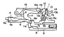
제1도는 본 발명에 의한 카세트 데크를 표시하는 개략 평면도.1 is a schematic plan view showing a cassette deck according to the present invention.

제2도는 그 개략 측면도.2 is a schematic side view thereof.

제3도 내지 제5도는 카세트 장전 동작 설명도.3 to 5 are diagrams illustrating a cassette loading operation.

제6도 내지 제9도는 카세트 이젝트 동작 설명도.6 to 9 are diagrams illustrating a cassette eject operation.

제10도는 제1도에 있어서 리일 유니트 구동기구의 개략 평면도.10 is a schematic plan view of the rail unit driving mechanism in FIG.

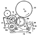
제11도는 FF/REW 동력전달기구부의 구성도.11 is a configuration diagram of the FF / REW power transmission mechanism.

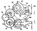
제12도는 정속/고속동력 전달기구부의 구성도.12 is a configuration of the constant speed / high speed power transmission mechanism.

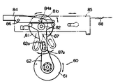
제13도는 센싱(sensing)기구의 일예를 표시한 구성도.13 is a configuration diagram showing an example of a sensing mechanism.

제14도는 센싱기구의 리세트 동작 설명도.14 is an explanatory diagram of reset operation of a sensing mechanism.

제15도 및 제16도는 선별레버 및 센싱동력레버의 동작 설명도.15 and 16 are explanatory views of operations of the selection lever and the sensing power lever.

제17도는 록 아암의 고정 해제 동작 설명도.17 is an explanatory view of the unlocking operation of the lock arm.

제18도는 헤드대의 전진 동작 설명도.18 is an explanatory diagram of the forward movement of the head stand.

제19도는 헤드대의 고정 해제 동작 설명도.19 is an explanatory view of the release operation of the head stand.

제20도 및 제21도는 FF 및 REW동작 설명도.20 and 21 are explanatory views of the FF and REW operations.

제22a도 및 (b)는 FF레버의 그릴 개구에 대한 위치결정을 표시하는 평면도 및 측면도.22A and 22B are a plan view and a side view showing positioning of the grill opening of the FF lever.

* 도면의 주요부분에 대한 부호의 설명* Explanation of symbols for main parts of the drawings

2 : 카세트압압레버 3 : 제1아암2: cassette press lever 3: first arm

4 : 제1레버 6 : 제2레버4: first lever 6: second lever

8 : 제3레버 11 : 요동레버8: third lever 11: rocking lever

12 : 규제아암 13 : 록 아암12: regulating arm 13: rock arm

15 : 카세트하아프 16 : 카세트호울더15: cassette half 16: cassette holder

25 : 헤드 28 : FF레버25: head 28: FF lever

29 : REW 레버 34 : 그릴29: REW lever 34: grill

37 : 제2아암 42 : 선별레버37: second arm 42: selection lever

50 : 모우터 53 : 플라이호일기어50: motor 53: fly foil gear

55 : 캡스턴 57 : 아이들러아암55 capstan 57 idler arm

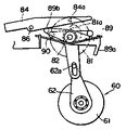
60, 63 : 리일유니트 62 : 센싱해제아암60, 63: Rial unit 62: Sensing release arm

68 : 헤드대 74 : 아이들러기어68: head stand 74: idler gear

81 : 캠기어 84 : 센싱아암81: cam gear 84: sensing arm

89 : 리세트아암 100 : 핀치 로울러89: reset arm 100: pinch roller

본 발명은 카세트데크에 관한 것이며, 특히 카세트 데크에 있어서 이젝트 기구의 기동기구에 관한 것이다. 카세트데크는 근년에 점차 소형화되는 경향에 있으며 특히 차재용 카세트 데크에 있어서는 카세트 데크의 수용되어야할 공간에 한계가 있기 때문에 카세트 데크의 소형화 박형화의 요청이 강하게 있었다.TECHNICAL FIELD The present invention relates to a cassette deck, and more particularly to a start mechanism of an eject mechanism in a cassette deck. Cassette decks have tended to become smaller in recent years, and in particular, in the on-vehicle cassette decks, there is a strong demand for miniaturization of cassette decks due to the limited space to be accommodated in the cassette decks.

그래서 본 발명은 기구를 단순화하여 카세트 데크의 소형화, 박형화에 기여할 수 있는 동시에 기구의 동작이 확실한 이젝트기구의 기동기구를 제공하는 것을 목적으로 한다.It is therefore an object of the present invention to provide a start mechanism of an eject mechanism, which can simplify the mechanism and contribute to miniaturization and thinning of the cassette deck and at the same time ensure the operation of the mechanism.

본 발명에 의한 이젝트기구의 기동기구에 있어서는 왕복동작이 자유롭게 설치되어서 그 왕복로에서 이젝트기구의 기동을 담당하는 동력 레버에 센싱아암을 회전이 가능하게 지지하며, 리일유니트의 회전정지때에 그 센싱아암이 리일유니트 구동모우터를 동력원으로 하는 회전캠기구와 걸어맞춤으로서 동력레버를 왕복동작시키며, 또한 연주위치에 장진된 카세트 하아트와 걸어맞춤이 가능하게 리세트 아암을 설치, 카세트 하아프가 이젝트된때에는 그 리세트 아암에 의해서 그 센싱아암을 요동시켜서 그 회전캠 기구와의 걸어맞춤을 강제적으로 해제하는 구성으로 되어 있다.In the start mechanism of the ejection mechanism according to the present invention, the reciprocating motion is freely installed, and the sensing arm is rotatably supported by a power lever that is responsible for the start of the ejection mechanism in the reciprocating path, and the sensing unit rotates when the rail unit stops rotating. The arm reciprocates the power lever by engaging a rotating cam mechanism powered by a real unit drive motor, and a reset arm is installed to allow the arm to engage with the cassette harat loaded at the playing position. At the time of ejection, the sensing arm is swung by the reset arm to forcibly release the engagement with the rotary cam mechanism.

다음 도면에 의거하여 본 발명의 실시예를 설명한다.An embodiment of the present invention will be described based on the following drawings.

제1도 및 제2도는 본 발명에 의한 카세트 데크를 표시한 개략평면도 및 개략 측면도이다.1 and 2 are schematic plan views and schematic side views showing a cassette deck according to the present invention.

제1및 제2도에 있어서 사이드 플레임(1)에는 카세트 압압레버(2)가 도면의 좌우방향에 있어서 접동이 자유롭게 걸어맞추어지며 또한 제1아암((3)이 축(3a)을 중심하여 요동이 자유롭게 추지되어 있다(제3도 참조). 제1아암(3)은 그 선단부에 형성된 장공(3b)에서 카세트 압압레버(2)에 설치된 핀(2a)에 걸어맞추어 있으며, 카세트하아프(15)의 장전시, 제3도에 표시한 바와같이, 카세트 압압레버(2)의 도면의 좌측방향으로의 이동에 의해서 반시계방향으로 요동한다. 카세트 압압레버(2)의 선단은 삽입된 카세트 하아프(15)의 후단이 맞닿아지도록 대략 L자형으로 굴곡되어 있다. 제1아암(3)에는 제1레버(4)가 요동 가능하게 지지되며, 당해 제1레버(4)는 제1아암(3)의 요동에 의해서 도면의 좌방향 즉 카세트 삽입방향으로 이동하여 이 이동시 스프링(5)에 의하여 사이드 플레임(1)에 대하여 도면의 우방향으로 부세된다.In FIG. 1 and FIG. 2, the cassette pressing lever 2 is freely engaged in the side frame 1 in the left and right directions of the drawing, and the first arm 3 swings about the axis 3a. The first arm 3 is engaged with the pin 2a provided on the cassette press lever 2 in the long hole 3b formed at the distal end thereof, and the cassette half 15 is held therein. ), It swings counterclockwise by movement in the left direction of the drawing of the cassette pressing lever 2. As shown in Fig. 3, the tip of the cassette pressing lever 2 is placed under the inserted cassette. The rear end of the ape 15 is bent in an approximately L shape so that the first lever 4 is pivotally supported by the first arm 3, and the first lever 4 is supported by the first arm ( By the swing of 3), it moves to the left direction of the drawing, that is, the cassette insertion direction. With respect to the frame (1) is biased in the right direction in the drawing.

제2레버(6)는 사이드 플레임(1)에 대하여 도면의 좌우 방향에 있어서 접동 자유롭게 걸어맞춤이 되어 있으며 제4도에 표시한 바와같이 제1레버(4)의 좌방향으로의 이동시 그 선단부에 설치된 돌기(6a)에서 제1레버(4)의 클릭(4a)에 걸어맞춤이 되므로서 제1레버(4)와 동시에 카세트 삽입방향(도면의 좌방향)으로 이동이 된다.The second lever 6 is slidably engaged with the side flame 1 in the left and right directions of the drawing, and as shown in FIG. 4, the second lever 6 is moved to the left end of the first lever 4 in the left direction. Since the engaging projection 6a is engaged with the click 4a of the first lever 4, the projection 6a moves in the cassette insertion direction (left direction in the drawing) simultaneously with the first lever 4.

제2레버(6)에는 제3레버(8)가 접동 자유로이 부착되어 또한 스프링(9)에 의해서 제2레버(6)에 대하여 카세트 삽입방향으로 부세되어 있다. 제3레버(8)는 제4도에서 명백한 바와같이 사이드 플레임(I)에 대하여 축(10)에 의해서 요동자유롭게 추지된 요동아암(11)의 일단(11a)에 그의 선단(8a)에서 걸어 맞춤하여 스프링(9)의 부세력에 의해서 요동아암(11)을 시계방향으로 부세한다.The third lever 8 is freely attached to the second lever 6 and is biased by the spring 9 in the cassette insertion direction with respect to the second lever 6. The third lever 8 is engaged at its tip 8a to one end 11a of the swinging arm 11 freely swung by the shaft 10 with respect to the side flame I as shown in FIG. The urging arm 11 is urged clockwise by the urging force of the spring 9.

사이드 플레임(1)에 대하여 규제아암(12)이 축(7a)에 의해서 요동이 자유롭게 추지되며 이 규제아암(12)에는 록아암(13)이 축(7b)에 의해서 요동 자유로이 추지되어 있으며 제4도에 표시된 바와같이 축(7a)의 주위에 설치되어 일단이 사이드 플레임(1)에 타단이 록아암(13)에 각각 걸어맞춤이 된 스프링(14)에 의해서 규제아암(12)이 반시계 방향으로 록아암(13)이 시계 방향으로 각각 부세되어 있다. 록아암(13)은 그 하단부(13a)가 제2레버(6)의 돌부(6b)에 걸어맞춤이 되어 있으며, 카세트하아프(15)의 장전시에 카세트 압압레버(2)에 연동하여 제2레버(6)의 돌부(6b)가 도면의 좌방향으로 이동하므로서 스프링(14)의 부세력에 의하여 시계방향으로 요동하여 카세트 하아프(15)가 완전이 안쪽으로 삽입된때에 제5도에 표시한 바와같이 카세트 압압레버(2)의 전단절곡부(2b)를 그의 후크부(13b)에서 고정이 된다.The control arm 12 is freely oscillated by the shaft 7a with respect to the side flame 1, and the lock arm 13 is freely oscillated by the axis 7b with the control arm 12. As shown in the figure, the regulating arm 12 is rotated counterclockwise by a spring 14 provided around the shaft 7a, one end of which is engaged with the side arm 1 and the other end of which is engaged with the lock arm 13, respectively. The lock arms 13 are biased clockwise, respectively. The lower arm 13a is engaged with the protrusion 6b of the second lever 6, and the lock arm 13 is interlocked with the cassette press lever 2 when the cassette half 15 is loaded. 5 when the cassette lower half 15 is completely inserted inward when the projection 6b of the two levers 6 is moved clockwise by the force of the spring 14 as it moves to the left in the drawing. As indicated in the figure, the shear bending portion 2b of the cassette pressing lever 2 is fixed at the hook portion 13b thereof.

카세트 호울더(16)는 사이드플레임(1)에 대하여 요동자유로이 추지되어 있으며 그 중간부에서 핀(16a)을 통하여 요동아암(11)의 선단장공(11b)에 걸어맞춤이 되어 있다. 그 결과 카세트 호울더(16)는 요동아암(11) 및 제3레버(8)를 통하여 스프링(9)에 의하여 도면의 시계방향으로 부세되므로서 제4도에서 명백한 바와같이 규제아암(12)의 단차부(12a)에 걸어맞춤이 되므로써 그 요동이 규제된다. 그리고 카세프 하아프(15)가 완전히 안쪽까지 삽입되어서 카세트 압압레버(2)의 절곡부(2b)가 록아암(13)에 의하여 고정이 되면 카세트 압압레버(2)에 작용하여 있는 스프링(5) 및(9)의 부세력에 의해서 록아암(13)을 통하여 규제아암(12)이 근소하게 시계방향으로 요동시킴으로써 제5도에 표시한 바와 같이 카세트 호울더(16)의 요동 규제가 해제된다. 이것에 의해서 카세트 호울더(16)는 요동아암(11)에 작용되어 있는 부세력에 의해서 시계방향으로 요동하여 완전히 안쪽까지 삽입된 카세트 하아프(15)를 연주위치까지 밀어내린다. 28은 테이프의 빨리보내기(FF)를 지령하는 FF, 29는 테이프의 되감기(REW)를 지령하는 REW레버이며, 이들 레버(28,29)는 긴 판상부재로 되며 서로 접동이 가능하게 포개어 합쳐서 장치의 전면부(도면의 우측부)에서 후부(도면의 좌측부)에 걸쳐서 뻗어있다.The cassette holder 16 is freely swinged with respect to the side frame 1, and is engaged with the front end hole 11b of the swinging arm 11 through the pin 16a at its middle portion. As a result, the cassette holder 16 is urged clockwise in the drawing by the spring 9 via the swinging arm 11 and the third lever 8, as shown in FIG. The swing is regulated by engaging the stepped portion 12a. Then, when the cassette half is fully inserted inward and the bent portion 2b of the cassette pressing lever 2 is fixed by the lock arm 13, the spring 5 acting on the cassette pressing lever 2 The fluctuation of the cassette holder 16 is canceled as indicated in FIG. 5 by rocking the regulating arm 12 slightly clockwise through the lock arm 13 due to the subordinate forces of (9) and (9). . As a result, the cassette holder 16 swings clockwise by the subordinate force acting on the swinging arm 11 and pushes the cassette lower half 15 inserted to the inside to the playing position. 28 is FF for fast forwarding of the tape (FF), 29 is a REW lever for commanding the rewinding of the tape (REW), and these levers (28, 29) are long plate members and are stacked together so that they can slide together. It extends from the front part (right part of drawing) to the rear part (left part of drawing).

레버(28,29)위에는 또한 긴판상의 캠레버(30)가 접동가능하게 포개어 합쳐져 있으며 이들 3장의 레버(28,29,30)은 각 양단부에 형성된 장공(28a,29a,30a) 및(28b, 29b, 30b)에서 샤시(17)에 고착된 축(31a) 및 (31b)에 접동 자유롭게 걸어맞춤이 되어 있다. 캠레버(30)의 장공(30b)이 폭의 축(31b)의 직경에 대략 같은데 대하여 레버(28,29)의 장공(28b,29b)의 폭은 제22a도에 표시한 바와같이 축(31b)의 주벽과의 사이에 좌우에 각각 소정의 극간(t)이 생기는 정도로 축(31b)의 직경보다 다르게 형성되어 있으며, 이것에 의해서 레버(28,29)는 제22a도,(b)도에 표시한 바와같이 선단부의 장공(28a,29a)에서 걸어맞춤이된 축(31a)을 중심으로 장공(28b,29b)의 폭방향 및 축(31b)의 축방향에서 요동이 가능하게 된다. 그 결과 레버(28,29)의 각 조작 보턴(32,33)을 그릴(34)의 개구(34a)에 장착할 때 장치본체와 그릴(34)과의 상대적인 위치 어긋남등이 생겨도 그릴(34)의 개구(34a)에 대하는 각 조작보턴(32,33)의 위치 결정을 확실하게 행할 수 있게 된다. 또한 제22a,(b)도에는 FF 레버(28)만이 표시되어 있으나 REW 레버(29)에 대하여도 같은 구성으로 되어 있다.On the levers 28 and 29, a long cam lever 30 is slidably stacked and these three levers 28, 29 and 30 are formed in the long holes 28a, 29a, 30a and 28b formed at each end. , 29b and 30b are slidably engaged with the shafts 31a and 31b fixed to the chassis 17. While the long hole 30b of the cam lever 30 is approximately equal to the diameter of the shaft 31b of the width, the width of the long holes 28b, 29b of the levers 28, 29 is as shown in FIG. 22A. Is formed differently from the diameter of the shaft 31b to the extent that a predetermined gap t is formed on the left and right sides between the main wall of the head). As a result, the levers 28 and 29 are formed in FIGS. 22a and (b). As indicated, oscillation is possible in the width direction of the long holes 28b and 29b and the axial direction of the shaft 31b about the axis 31a engaged in the long holes 28a and 29a of the tip portion. As a result, when the operation buttons 32 and 33 of the levers 28 and 29 are attached to the opening 34a of the grill 34, even if there is a relative position shift between the apparatus body and the grill 34, the grill 34 It is possible to reliably position each of the operation buttons 32 and 33 with respect to the opening 34a. In addition, although only the FF lever 28 is shown by FIG. 22a, (b), the structure is the same also about the REW lever 29. As shown in FIG.

FF 레버(28), REW 레버(29)에는 각각 절곡부(35,36)가 형성되어 있고, 이들 절곡부(35,36)는 제2아암(37)의 양단돌부(37a,37b)에 맞닿아 있다. 제2아암(37)은 캠레버(30)에 고정된 핀(38)에 부착되어 있다.The FF lever 28 and the REW lever 29 are formed with bent portions 35 and 36, respectively, and the bent portions 35 and 36 are fitted to both end portions 37a and 37b of the second arm 37. Is touching. The second arm 37 is attached to a pin 38 fixed to the cam lever 30.

또 캠레버(30)와 축(31b)과의 사이에는 스프링(39)이 장치되어 있다. 여기서 FF 레버(28) 및 REW 레버(29)는 단독으로 압압된때에는 FF 및 REW를 지령으로 하는 조작레버로서 작용을 하나 쌍방이 동시에 압압된때에는 이젝트(EJECT)를 지령하는 조작레버로서 작용을 한다. 즉 양레버(28,29)가 동시에 압압된 때의 핀(38)의 이동량은 각각 단독으로 압압된 때의 이동량보다 크게되며 이 이동량의 다름에 의하여 이젝트 동작을 행한다. 또한 FF 레버(28) 및 REW 레버(29)를 단독으로 조작한때는 후술하는 록기구에 의해서 고정이 되나 양레버(28,29)가 동시에 압압된 때에는 고정이 되지 않도록 되어 있다.A spring 39 is provided between the cam lever 30 and the shaft 31b. Here, the FF lever 28 and the REW lever 29 act as an operating lever for commanding FF and REW when pressed alone, but act as an operating lever for commanding the eject when both are pressed simultaneously. . That is, the movement amount of the pin 38 when both levers 28 and 29 are simultaneously pressed is larger than the movement amount when the lever 38 is pressed alone, and the ejection operation is performed by the difference of this movement amount. When the FF lever 28 and the REW lever 29 are operated alone, they are fixed by the locking mechanism described later, but they are not fixed when both levers 28 and 29 are pressed simultaneously.

핀(38)의 이동량이 그대로 캠레버(30)이 이동량으로 되며 캠레버(30)는 FF 레버(28) 및 REW 레버(29)의 동시 압압에 의한 이젝트 조작에 따라서 도면의 좌방향으로의 소정량이 이동되었을때는 클릭(30c)이 요동자유로운 제3아암(40)의 일단이 맞닿아서 이것을 반시계 방향으로 요동시킨다. 이러므로서 제3아암(40)의 타단은 스프링(41)에 의해서 도면의 상방향으로 부세된 선별 레버(42)를 통하여 요동이 자유로운 록해제레버(43)의 일단 43a을 압압하여 이것을 요동시킨다.The cam lever 30 is moved as it is, and the cam lever 30 moves to the left in the drawing in accordance with the ejection operation by simultaneous pressing of the FF lever 28 and the REW lever 29. When the amount is moved, one end of the third arm 40, which is free to swing when the click 30c moves, abuts and swings it counterclockwise. Thus, the other end of the third arm 40 presses one end 43a of the unlocking lever 43, which is freely swingable, via the sorting lever 42 biased upward by the spring 41 to oscillate it.

록해제레버(43)는 요동함으로써 그 타단(43b)이 제8도의 상방향으로 이동하고, 카세트 장진에 의해서 당해 타단(43b)에 걸어맞춤이 가능한 위치까지 가져오게 된 제1레버(4)의 선단부를 밀어올리므로서 제1레버(4)의 클릭(4a)과 제2레버(6)의 돌부(6a)와의 걸어맞춤을 해제한다. 이것에 의해 제2레버(6)는 우측 방향으로 이동하여 제6도에 표시한 바와같이 돌기(6c)가 요동아암(11)의 일단(11a)에 걸어맞춤으로써 요동아암(11)을 반시계 방향으로 요동시킨다. 이것에 의해서 카세트 호울더(16)는 카세트하아프(15)를 들어올린다. 또 카세트 하아프(15)의 상승시 록아암(13)은 우방향으로 이동하는 제2레버(6)의 돌부(6b)에 의해서 그 하단부(13a)가 압압되므로서 반시계 방향으로 요동하며 제7도에 표시한 바와같이 카세트 하아프(15)의 상승이 완료한 시점에서 카세트 압압레버(2)의 절곡부(2b)의 고정을 해제한다. 따라서 카세트 압압레버(2)는 우방향으로 이동한 카세트 하아프(15)를 이젝트한다. 이 이젝트시에 있어서 카세트 하아프(15)의 들어올림 및 이젝트에 필요로 하는 힘은 장전시에 잡아늘린 스프링(5) 및(9)에 의하여 주어진다.The unlocking lever 43 swings so that the other end 43b is moved upward in FIG. 8 and brought to the position where the other end 43b can be engaged by the cassette longing. The engagement between the click 4a of the first lever 4 and the protrusion 6a of the second lever 6 is released by pushing up the tip portion. As a result, the second lever 6 moves in the right direction, and as shown in FIG. 6, the projection 6c is engaged with the one end 11a of the swinging arm 11 to counterclockwise the swinging arm 11. Rock in the direction. As a result, the cassette holder 16 lifts the cassette half 15. In addition, when the cassette lower half 15 is raised, the lock arm 13 swings in the counterclockwise direction as the lower end portion 13a is pressed by the protrusion 6b of the second lever 6 moving in the right direction. As shown in FIG. 7, the bent portion 2b of the cassette press lever 2 is released from the point at which the cassette lower half 15 is lifted. Accordingly, the cassette press lever 2 ejects the cassette lower half 15 moved in the right direction. The force required for lifting and ejecting the cassette half 15 during this ejection is given by the springs 5 and 9 stretched during loading.

제10도는 본 발명에 의한 카세트 데크에 있어서 리일유니트 구동기구를 표시하고 있다.10 shows a real unit drive mechanism in the cassette deck according to the present invention.

제10도에서 모우터(50)의 회전축(51)에 결합된 풀리(52)와 플라이휘일(53)과의 사이에 벨트(54)가 가설되어 있다. 또한 플라이휘일(53)이 중심축 캡스턴(55)이다. 플라이휘일(53)과 동축 또한 일체로 기어(56)가 설치되어 있다. 기어(56)에는 제12도에 표시한 바와같이 샤시(17)에 대하여 캡스턴(55)의 주위에 요동이 가능하게 또한 스프링(58)에 의하여 반시계 방향으로 부세된 아이들러 아암(57)에 회전자유롭게 추지된 아이들러기어(59)가 맞물려 있으며 이 아이들러기어(59)는 플레이상태일 때 권취측 리일유니트(60)와 일체적으로 구성된 리일구동기어(61)에 맞물리도록 되어 있다. 리일유니트(60)에는 리일구동기어(61)와 소정의 마찰부재를 통하여 걸어맞춘 센싱해제아암(62)이 설치되어 있다.In FIG. 10, the belt 54 is hypothesized between the pulley 52 and the flywheel 53 coupled to the rotation shaft 51 of the motor 50. The flywheel 53 is the central axis capstan 55. The gear 56 is coaxially and integrally provided with the flywheel 53. As shown in FIG. 12, the gear 56 rotates about an idler arm 57 which is oscillated around the capstan 55 with respect to the chassis 17 and which is biased counterclockwise by the spring 58. As shown in FIG. The freely held idler gear 59 is engaged, and the idler gear 59 is engaged with the rail drive gear 61 integrally formed with the winding side rail unit 60 when it is in a play state. The rail unit 60 is provided with a sensing release arm 62 engaged with the rail drive gear 61 through a predetermined friction member.

공급측 리일유니트(63)에는 예컨대 2개의 걸림크릭(64a,64b)이 설치되어 있다. 샤시(17)에 설치된 핀(65)에 의해서 요동이 자유롭게 추지된 래치 아암(66)은 스프링(67)에 의해서 도면의 시계방향으로 부세되어 일단(66a)에서 걸림그릭(64a,6 4b)와 걸어맞춤할 수 있도록 설치되어서 래치 기구를 구성한다. 래치아암(66)의 타단(66b)은 플레이 상태으로의 이행시, 헤드대(68)의 전진위치로의 이동에 의해서 헤드대(68)의 돌기(68a)에 의해서 압압이 되어 반시계방향으로 회동시키므로서 래처 기구를 해제하도록 되어 있다.The supply side rail unit 63 is provided with, for example, two locking creases 64a and 64b. The latch arm 66 freely swinged by the pin 65 provided on the chassis 17 is urged clockwise in the drawing by the spring 67, and at one end 66a, the latch arms 64a, 6 4b and It is installed so that it can be engaged and comprises a latch mechanism. The other end 66b of the latch arm 66 is pressed by the projection 68a of the head stand 68 in the counterclockwise direction by the movement of the head stand 68 to the forward position at the transition to the play state. The latch mechanism is released by rotating.

리미터기어(69)는 제12도에서 명백한 바와같이 축(70)에 의해서 샤시(17)에 요동자유로이 추지된 리미터아암(71)에 회전이 자유로이 추지되어서 헤드대(68)가 후퇴위치에 있을때에는 리미트아암(71)을 도면이 시계방향으로 부세하는 스프링(72)에 의해서 상기 플라이 휘일기어(53)에 맞물리도록 되어 있다. 이때 헤드대(68)의 각공단부(68c)에 아이들러아암(57)의 핀(57a)이 걸어맞춤이 되어 아이들러아암(57)이 도면의 시계방향으로 요동하므로 아이들러아암(59)는 리일구동기어(61)에 맞물리지 않는다. 그리고 헤드대(68)가 전진위치에 이동하며 플레이 상태로 이행하면 헤드대(68)의 부쉬(68b)가 리미터아암(71)을 도면의 시계방향으로 요동시켜서, 플라이휘일기어(53)와 리미터기어(69)와의 맞물림을 해제시키며 한편 헤드대(68)의 각공단부(68c)와 아이들러아암(57)의 핀(57a)와의 걸어맞춤이 해제되므로 아이들러기어(59)가 리일구동기어(61)에 맞물려서 리일유니트(60)를 정속 구동한다.When the limiter gear 69 is freely rotated on the limiter arm 71 which is freely swinged on the chassis 17 by the shaft 70, as shown in FIG. 12, when the head rest 68 is in the retracted position, The limit arm 71 is engaged with the flywheel gear 53 by a spring 72 that squeezes clockwise. At this time, the pin 57a of the idler arm 57 is engaged with each corner 68c of the head stage 68, and the idler arm 57 swings clockwise in the drawing, so the idler arm 59 is driven by the rail. It does not mesh with the gear 61. When the head stage 68 moves to the forward position and shifts to the play state, the bush 68b of the head stage 68 swings the limiter arm 71 in the clockwise direction of the drawing, whereby the flywheel gear 53 and the limiter are moved. Since the engagement between the gear 69 and the corner end 68c of the head rest 68 and the pin 57a of the idler arm 57 are released, the idler gear 59 is the rail driving gear 61. ), The rail unit 60 is driven at constant speed.

리미터기어(69)에는 축(73)에 의해서 회전이 자유로이 추지된 아이들러기어(74)가 맞물려 있다. 아이들러기어(74)의 축(73)은 제11도에서 명백한 바와같이 아이들러레버(75)에 고착되어서 샤시(17)에 천설된 장공(76)에 따라서 직선적으로 이동이 가능하게 구성이 되어 있다. 아이들러레버(75)가 스프링(77)에 의해서 도면의 상방향으로 부세되어 있으므로, 아이들러기어(74)는 통상 FF 기어(78)를 통하여 권취측의 리일구동기어(61)를 구동한다(FF).The limiter gear 69 is engaged with an idler gear 74 whose rotation is freely held by the shaft 73. As is apparent from FIG. 11, the shaft 73 of the idler gear 74 is fixed to the idler lever 75 and is configured to be linearly movable along the long hole 76 installed in the chassis 17. Since the idler lever 75 is biased upward in the drawing by the spring 77, the idler gear 74 normally drives the rail drive gear 61 on the winding side via the FF gear 78 (FF). .

한편 후술하는 REW 조작에 관련하여 절환레버(79)가 제11도에 표시한 바와같이 아이들러레버(75)를 스프링(77)에 버티면서 하방향으로 이동시키므로서 아이들러기어(74)는 공급측의 기일구동기어(80)와 맞물려서 이것을 구동한다(REW).On the other hand, in connection with the REW operation described later, as shown in FIG. 11, the switching lever 79 holds the idler lever 75 against the spring 77 and moves downwards, so that the idler gear 74 is the date of supply. It meshes with the drive gear 80 to drive this (REW).

또 다시 제10도에서 샤시(17)에는 캠기어(81)가 축(82)에 의해서 회전이 자유로이 추지되어 있으며 이 캠기어(81)에는 모우터(50)의 구동 토오크가 3개의 기어(83a,83b,83c)를 경유하여 전달된다. 이 캠기어(81)의 캠(81a)에 적합하게 걸어맞춤이 가능한 클릭(84a)을 가지는 센싱아암(84)이 제13도에 표시한 바와 같이 센싱동력레버(85)에 대하여 축(86)에 의해서 요동이 자유로이 추지되어 있다.In FIG. 10, the cam 17 is freely rotated by the shaft 82 in the chassis 17, and the driving torque of the motor 50 is three gears 83a. Delivered via (83b, 83c). As shown in FIG. 13, a sensing arm 84 having a click 84a that can be properly engaged with the cam 81a of the cam gear 81 has a shaft 86 with respect to the sensing power lever 85. As shown in FIG. The fluctuation is freely held by.

한편 캠기어(81)와 동축에 T형 아암(87)이 요동자유로이 추지되어서 이 T형 아암(87)은 하단 장공(87a) 에서 상술한 센싱 해제아암(62)의 핀(62a)에 걸어맞추어져 있다. 리일유니트(60)가 회전하고 있을 때에는 그 회전방향에 응하여 센싱해제아암(62)이 우 또는 좌방향으로 요동하여 센싱아암(84)을 제13도의 반시계방향으로 요동시켜 그 클릭(84a)을 캠기어(81)의 캠(81a)과 걸어맞춤이 가능한 위치로 퇴피시킨다.On the other hand, the T-shaped arm 87 is oscillated freely and coaxially with the cam gear 81, so that the T-shaped arm 87 is engaged with the pin 62a of the sensing release arm 62 described above in the lower slot 87a. Lost When the reel unit 60 is rotating, the sensing release arm 62 swings in the right or left direction in response to the rotational direction, and the sensing arm 84 swings in the counterclockwise direction in FIG. 13 to release the click 84a. The cam gear 81 is retracted to a position where the cam gear 81 can engage with the cam 81a.

리일 유니트(60)의 회전이 정지하면 센싱해제아암(62)이 요동하지 않으므로 센싱아암(84)의 클릭(84a)이 캠기어(81)의 외주내벽의 작용에 의해서 캠(81a)과 걸어맞춤이 가능한 위치에 가져와서 캠기어(81)의 회전 토오크에 의해서 센싱아암(84)이 제13도의 좌방향으로 이동시킨다. 센싱아암(84)과 센싱동력레버(81)와는 축(86)을 통하여 결합되어 있으므로 센싱동력레버(85)도 센싱아암(84)과 일체로 스프링(88)의 탄성력에 버티면서 이동한다. 센싱아암(84)의 클릭(84a)과 캠기어(81)의 캠(81a)과의 걸어맞춤이 벗어나면 스프링(88)의 복원력에 의해서 원위치에 복귀한다.When the rotation of the rail unit 60 is stopped, the sensing release arm 62 does not swing, so that the click 84a of the sensing arm 84 engages with the cam 81a by the action of the outer circumferential wall of the cam gear 81. In this possible position, the sensing arm 84 is moved to the left in FIG. 13 by the rotational torque of the cam gear 81. Since the sensing arm 84 and the sensing power lever 81 are coupled through the shaft 86, the sensing power lever 85 also moves integrally with the sensing arm 84 while supporting the elastic force of the spring 88. When the engagement of the click 84a of the sensing arm 84 and the cam 81a of the cam gear 81 is out of alignment, it returns to original position by the restoring force of the spring 88. FIG.

또 제14도에 표시한 바와같이 T형 아암(87)과 동축으로 리세트 아암(89)이 요동자유로이 설치되며 또한 스프링(90)에 의해 도면의 시계방향으로 부세되어 있다. 이 리세트 아암(89)의 일단경사부(89a)는 통상 제1도에 표시한 바와같이 카세트 하아프의 장전측에 돌출되어 있으며, 삽입된 카세트 하아프가 강하하는 때에 이 카세트 하아프에 의해서 도면의 반시계방향으로 요동시켜서 카세트 하아프가 이젝트되면 스프링(90)의 부세력에 의해서 제14도의 시계방향으로 요동하여 그의 타단(89b)에서 센싱아암(84)을 도면의 반시계방향으로 요동시킨다.As shown in FIG. 14, the reset arm 89 is provided with a swing free path coaxially with the T-shaped arm 87, and is biased clockwise in the drawing by the spring 90. As shown in FIG. One end of the inclined portion 89a of the reset arm 89 is projected to the loading side of the cassette lower half as shown in FIG. 1, and the cassette lower half lowers when the inserted cassette lower half descends. When the cassette half is ejected by oscillating in the counterclockwise direction of the drawing, the cassette half is ejected and oscillated in the clockwise direction of FIG. Let's do it.

이것에 의하면 센싱아암(84)의 클릭(84a)과 캠기어(81)의 캠(81a)과의 걸어맞춤이 벗어나기 직전에 후술하는 자동 이젝트 동작이 완료하여 모우터(50)가 정지하여도 리세트아암(89)의 작용에 의해서 센싱아암(84)의 클릭(84a)과 캠기어(81)의 캠(81a)과의 걸어맞춤을 확실하게 해제할 수 있기 때문에 다음의 카세트 장정 동작에 지장을 가져오는 일은 없다.According to this, the automatic ejection operation described below is completed immediately before the engagement between the click 84a of the sensing arm 84 and the cam 81a of the cam gear 81 is completed, and the motor 50 stops. The engagement of the click 84a of the sensing arm 84 and the cam 81a of the cam gear 81 can be reliably released by the action of the set arm 89, thus preventing the following cassette mounting operation. There is no import.

제1도에 있어서 선별레버(42)와 센싱동력레버(85)는 서로 병렬로 설치되어 서로 단독으로 그렇지 않으면 일체로 도면의 아래 방향으로 접동할 수 있는 구성으로 되어 있다.In FIG. 1, the selection lever 42 and the sensing power lever 85 are arranged in parallel with each other so as to be able to slide in the downward direction of the figure independently of each other or integrally.

또 선별레버(42)는 록해제레버(43)의 일단(43a)을 작용점으로 하고 있는 동시에 당해 일단(43a)을 지점으로 하여 스프링(41)의 부세력에 버티면서 센싱동력레버(85)와의 걸어맞춤위치와 비 걸어맞춤위치와의 사이에서 요동가능하며 그의 오목부(42a)와 센싱동력레버(85)의 절곡부(85a)와의 걸거나 벗겨짐을 선택적으로 하도록 되어 있다. 헤드대(68)가 전진위치에 있는 플레이 상태에 있어서는 제15도에 표시한 바와같이 선별레버(42)의 오목부(42a)와 센싱 동력레버(85)의 절곡부(85a)와는 걸어맞춤상태에 있으며 테이프 종단으로 되어서 제13도에 있어서 설명한 센싱 동작에 의해서 센싱동력레버(85)가 제1도의 하방향으로 이동할때 선별레버(42)도 일체로 이동하므로서 이것에 의해서 록해제레버(43)가 수동이젝트 동작시와 마찬가지로 선별레버(42)에 의하여 구동이되므로 테이프 종단에서 자동적으로 이젝트 동작이 행하여지는 것이 된다.In addition, the selection lever 42 has the one end 43a of the unlocking lever 43 as a functioning point, and the one end 43a as a point, and supports the biasing force of the spring 41, and with the sensing power lever 85. It is possible to swing between the engaged position and the non-engaged position, and to selectively engage or peel off the recessed portion 42a and the bent portion 85a of the sensing power lever 85. In the play state where the head rest 68 is in the forward position, as shown in FIG. 15, the recess 42a of the selection lever 42 and the bent portion 85a of the sensing power lever 85 are engaged with each other. When the sensing power lever 85 moves downward in FIG. 1 by the sensing operation described with reference to FIG. 13 and becomes a tape end, the selection lever 42 also moves integrally, thereby releasing the lever 43 Is driven by the selection lever 42 as in the manual eject operation, the eject operation is automatically performed at the end of the tape.

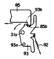
한편 제16도에 표시한 바와같이 FF 또는 REW 시에는 FF 테버(28) 또는 REW 레버(29)가 그 선단에서 선별레버(42)의 입상부(42b)를 압압하여 선별레버(42)를 요동시키며 선별레버(42)의 오목부(42a)와 센싱동력레버(85)의 절곡부(85a)와의 걸어맞춤이 해제되어 있으므로 센싱동작에 의해서 센싱동력에 레버(85)가 이동하여도 선별레버(42)는 이동하지 않고 이젝트 동작은 행하여지지 않는다. 또한 제17도에 표시한 바와같이 축(31a)에 의해서 요동자유로이 추지되며 또한 스프링(92)에 의해서 도면의 시계방향으로 부세된 록아암(93)이 설치되어 있으며 이 록아암(93)의 록핀(93a)에 의해서 제20도 또는 제21도에 표시한 바와같이 FF 레버(28) 또는 REW 레버(29)가 압압된 상태에 고정이 되어 있으며 센싱동력레버(85)가 이동할때 그 압하부(85b)가 록아암(93)의 입하부(93b)를 압압하여 록아암(93)을 제16도의 반시계방향으로 요동시키므로서 FF레버(28) 또는 REW레버(29)의 고정이 해제된다.On the other hand, as shown in FIG. 16, in the case of FF or REW, the FF tab 28 or the REW lever 29 presses the standing part 42b of the selection lever 42 at its tip and swings the selection lever 42. Since the engagement between the concave portion 42a of the selection lever 42 and the bent portion 85a of the sensing power lever 85 is released, even if the lever 85 is moved to the sensing power by the sensing operation, the selection lever ( 42 does not move and no eject operation is performed. In addition, as shown in FIG. 17, the rocking free path is detected by the shaft 31a, and the lock arm 93, which is biased in the clockwise direction in the drawing by the spring 92, is provided, and the lock pin of the lock arm 93 is provided. As shown in FIG. 20 or FIG. 21 by 93a, the FF lever 28 or the REW lever 29 is fixed in the pressed state, and the pressing portion when the sensing power lever 85 is moved ( 85b) presses the inlet portion 93b of the lock arm 93 and swings the lock arm 93 in the counterclockwise direction of FIG. 16 so that the fixing of the FF lever 28 or the REW lever 29 is released.

또 헤드대(68)가 후퇴위치에 있을때에는 제16도에 표시한 바와같이 핀치로울러 유니트(91)가 축(31a)을 중심으로 도면의 반시계방향으로 회동하여 그 단부(91a)에서 선별레버(42)의 입하부(42c)를 압압하여 선별레버(42)를 요동시키므로서 FF 또는 REW시와 같이 이젝트 동작은 행하여지지 않는다. 이제 센싱 동력레버(85)만이 이동을 하면 제18도에 표시한 바와같이 축(31a)에 의해서 요동이 자유로이 추지되며 또한 스프링(94)에 의해서 도면의 시계방향으로 부세되어 그 단부(95a)에서 헤드대(68)의 절곡부(680)에 걸어맞춤되므로서 헤드내(68)를 후퇴위치에 고정되어 있던 록아암(95)이 센싱동력레버(85)의 입하부(85b)에 의해서 제19도에 표시된 바와같이 도면의 반시계방향으로 요동이 되므로 헤드대(68)의 고정이 해제된다. 제18도에서 헤드대(68)는 구성(68e)에서 핀치로울러 유니트(91)의 핀(91b)와 걸어맞춤이 되어있고 헤드대(68)의 고정이 해제되므로서 핀치로울러 유니트(91)와 샤시(17)와의 사이에 장설된 스프링(96)에 의해서 헤드대(68)에 전진력이 부여된다. 또 헤드대(68)는 그 선단입상부(68f)에서 샤시(17)에 축(97)을 통하여 요동자유로이 추지된 아암(98)에도 걸어맞춤이 되어있고 아암(98)을 도면의 시계방향으로 걸어맞춤이 되어있고 아암(98)을 도면의 시계방향으로 부세하는 스프링(99)에 의하여도 전진력이 부여되어 화살표시 방향으로 이동한다. 헤드대(68)의 전진과 동시에 핀치로울러 유니트(91)가 도면의 시계방향으로 요동하여 핀치로울러(100)가 전진한다. 이젝트시는 제9도에 표시한 바와같이 스프링(102)의 부세력에 의해 복귀하는 레버(101)에 의해서 아암(98)이 반시계방향으로 회동시키므로서 헤드대(68)는 후퇴하여 핀치로울러(100)도 동시에 후퇴하여 당초의 상태로 복귀되며 록아암(95)에 의해서 후퇴위치에 고정이 된다.When the head rest 68 is in the retracted position, as shown in FIG. 16, the pinch roller unit 91 rotates about the shaft 31a in the counterclockwise direction of the drawing, and at the end 91a of the selection lever. While pressing the entrance part 42c of 42, the selection lever 42 is rocked, the eject operation | movement is not performed like FF or REW. Now, when only the sensing power lever 85 moves, the swing is freely held by the shaft 31a as shown in FIG. 18, and is also pushed clockwise in the drawing by the spring 94 at the end portion 95a. The lock arm 95, which is engaged with the bent portion 680 of the head stage 68 and is fixed to the retracted position in the head 68, is formed by the inlet portion 85b of the sensing power lever 85. As shown in the figure, the head base 68 is released because the swing is made in the counterclockwise direction of the drawing. In Fig. 18, the head stage 68 is engaged with the pin 91b of the pinch roller unit 91 in the configuration 68e, and the pinch roller unit 91 is released as the head stage 68 is released. The forward force is applied to the head base 68 by the spring 96 provided between the chassis 17. The head stage 68 is also engaged with the arm 98, which is freely oscillated through the shaft 97 on the chassis 17 at its tip end portion 68f, and the arm 98 clockwise in the figure. A forward force is also applied by the spring 99 which is engaged and pushes the arm 98 clockwise in the figure, and moves in the direction of the arrow. At the same time as the head stage 68 is advanced, the pinch roller unit 91 swings clockwise in the drawing, and the pinch roller 100 moves forward. At the time of ejection, as shown in FIG. 9, as the arm 98 rotates counterclockwise by the lever 101 returned by the biasing force of the spring 102, the head rest 68 is retracted to pinch roller. The 100 is also retracted at the same time to return to its original state and is fixed to the retracted position by the lock arm 95.

다음에 빨리 보내기(FF) 및 감아되감기(REW)동작에 대하여 설명을 한다.Next, the fast forward (FF) and rewind (REW) operations will be described.

카세트가 장전되어서 테이프 데크가 플레이 동작중에 제20도에 표시한 바와같이 FF 레버(28)가 압압조작이 되면 FF 레버(28)의 돌기(28a)가 록아암(93)의 록핀(93a)에 걸어 맛춤이 되어서 FF 레버(28)가 작동위치에 고정되는 동시에 캠부(28b)가 헤드대(68)에 고정이 되어 헤드대 핀(102)을 도면의 우측방향으로 아암하므로 헤드대(68)는 조금 후퇴한다. 그리고 핀치로울러(100)가 후퇴하여 캡스턴(55)으로의 압접상태가 해제되는 동시에 헤드(25)가 테이프에 가볍게 접촉하는 상태로 된다. 이때 제12도에 표시한 바와같이 헤드대(68)의 각 공단부(68c)에 의해서 아이들러아암(57)의 핀(57a)이 도면의 하방에 밀어내려져서 아이들러아암(57)이 도면의 시계방향으로 회동이 되어 리일 구동기어(61)와 아이들러기어(59)와의 맞물림이 해제된다.When the cassette is loaded and the tape deck is in play, as shown in FIG. 20, when the FF lever 28 is pressed, the projection 28a of the FF lever 28 is applied to the lock pin 93a of the lock arm 93. As shown in FIG. The FF lever 28 is fixed to the operating position while the cam portion 28b is fixed to the head stage 68, and the head stage pin 102 is armed to the right side of the drawing. Retreat a bit. Then, the pinch roller 100 retreats to release the pressure contact to the capstan 55 and at the same time the head 25 is in light contact with the tape. At this time, as shown in FIG. 12, the pins 57a of the idler arm 57 are pushed down by the respective satin portions 68c of the head rest 68 so that the idler arm 57 is clocked in the figure. Direction is rotated, and the engagement between the real drive gear 61 and the idler gear 59 is released.

한편 동시에 헤드대 부쉬(68b)와 리미터아암(71)과의 걸어맞춤이 해제되므로 스프링(72)의 부세력에 의해서 리미터아암(71)이 도면의 시계방향으로 요동하여 리미터기어(69)가 플라이휘일기어(53)와 맞물려서 고속회전 토오크가 플라이휘일기어(53)로부터 리미터리어(69) 아이들러기어(74)및 FF기어(78)를 통하여 리일구동기어(61)에 공급이 된다.At the same time, since the engagement between the head-to-bush bush 68b and the limiter arm 71 is released, the limiter arm 71 swings clockwise in the drawing due to the biasing force of the spring 72 so that the limiter gear 69 can fly. The high-speed rotational torque is engaged with the wheel gear 53 and supplied from the fly wheel gear 53 to the rail drive gear 61 through the limiter 69 idler gear 74 and the FF gear 78.

이와같이 하여서 테이프 데크가 빨리 보내는 동작을 하는 것이다. 빨리 보내는 동작을 정지할 경우에 제19도의 상태에서 REW레버(29)를 가볍게 압압조작을 하면 REW레버(29)의 돌기(29a)가 록핀(93a)을 도면의 우방향에 근소하게 압압하므로 FF레버(28)의 돌기(28a)와 록핀(93a)과의 걸어맞춤이 벗겨져서 FF레버(28)가 스프링(39)의 탄발력에 의해서 복구하여 카세트 데크는 당초의 플레이 상태로 복귀된다. 또 빨리 보내는 동작중에 테이프종료 상태가 생기면 상기한 리일 유니트 회전정지 센싱기구(제13도 참조)가 작동하여 이것에 의해서 제18도에서 설명한 바와같이 센싱동력레버(85)의 이동에 따라서 FF레버(28)의 고정이 해제되는 동시에 헤드대(68)가 전진하여 플레이상테로 복귀된다. 다음에 되감긴 동작을 행하는 경우에는 REW레버(29)를 강하게 압압조작을 하면 REW레버(29)는 제21도와 같이 REW레버(29)의 돌기(29a)가 록핀(93a)에 걸어맞춤하므로서 작동위치에 고정이 된다. 그러면 FF때와 마찬가지로 캠부(29b)에 의하여 헤드대 핀(102)이 화살표시 방향으로 압압이 되므로 헤드대(68)가 후퇴하여 아이들러기어(59)와 리일구동기어(61)와의 맞물림이 해제된다. 동시에 제11도에 표시한 바와같이 REW레버(29)의 압압조작에 관련하여 제2아암(37)이 핀(38)을 중심으로 도면의 시계방향으로 요동하여 이것에 의해서 제2아암(37)에 핀(79a)을 통하여 걸어맞춤한 절환레버(79)가 도면의 화살표시방향으로 이동하여, 아이들러레버(79)를 도면의 하방향으로 이동시키므로 아이들러기어(74)가 장공(76)에 따라서 직선적으로 이동하여 리일구동기어(80)에 맞물려서 고속회전 토오크가 플라이 휘일기어(53)로부터 리미터기어(69)및 아이들러기어(74)를 통하여 구동리일 구동기어(80)에 공급되어 되돌려 감는 동작이 행하여진다.In this way, the tape deck sends quickly. In the state of FIG. 19, when the quick sending operation is stopped, if the REW lever 29 is lightly pressed, the projection 29a of the REW lever 29 slightly presses the lock pin 93a in the right direction of the drawing. The engagement of the projection 28a of the lever 28 and the lock pin 93a is peeled off, and the FF lever 28 recovers by the spring force of the spring 39, and the cassette deck is returned to the original play state. In addition, if a tape end condition occurs during the quick sending operation, the above-mentioned rail unit rotation stop sensing mechanism (see FIG. 13) is operated, thereby causing the FF lever (see FIG. 18) to move as the sensing power lever 85 moves. 28 is released, and at the same time, the head rest 68 advances and returns to the play position. In the case where the rewinding operation is performed next, if the REW lever 29 is pressed strongly, the REW lever 29 operates as the projection 29a of the REW lever 29 engages with the lock pin 93a as shown in FIG. It is fixed in position. Then, as in the case of FF, the head-to-pin 102 is pushed in the direction of the arrow by the cam portion 29b, so that the head-base 68 is retracted and the engagement between the idler gear 59 and the real driving gear 61 is released. . At the same time, as shown in FIG. 11, in connection with the pressing operation of the REW lever 29, the second arm 37 swings clockwise in the drawing about the pin 38, thereby causing the second arm 37 to be moved. The switching lever 79 engaged through the pin 79a moves in the direction of the arrow in the drawing, and moves the idler lever 79 in the downward direction in the drawing, so that the idler gear 74 moves along the long hole 76. It moves linearly and meshes with the rail drive gear 80 so that the high-speed rotational torque is supplied from the flywheel gear 53 to the drive rail drive gear 80 via the limiter gear 69 and the idler gear 74 and then rolled back. Is done.

이상 설명한 바와같이 본 발명에 의한 이젝트기구의 기동기구에 의하면 왕복 동작이 자유로이 설치된 그 왕복로에서 이젝트 기구의 기동을 담당하는 동력레버에 센싱아암을 회전이 가능하게 지지하여 리일유니트의 회전정지 때에 이 센싱아암이 리일유니트 구동모우터를 동력원으로 하는 회전 캠기구와 걸어맞춤함으로써 동력레버를 왕복동작시키며 또한 연주위치에 장진된 카세트 하아프 걸어맞춤이 가능하게 리세트 아암을 설치시 카세트 하아프가 이젝트된 때에는 그 리세트 아암에 의해서 그 센싱아암을 요동시켜서 그 회전 캠 기구와의 걸어맞춤을 강제적으로 해제하도록 구성하였으므로 이젝트 완료직후에 전원 오프로 되며 회전캠기구와 센싱아암과의 걸어맞춤이 해제되기 전에 모우터가 정지되는 일이 생겨도, 리세트 아암의 작용에 의해서 기구가 초기상태로 복귀할 수 있기 때문에 다음의 카세트장진동작에 하등의 지장을 가져오는 일은 없다.As described above, according to the starting mechanism of the ejection mechanism according to the present invention, the sensing arm is rotatably supported by a power lever that is responsible for starting the ejection mechanism in the reciprocating path in which the reciprocating motion is freely provided. The sensing arm engages with the rotary cam mechanism that uses the real unit drive motor as a power source to reciprocate the power lever, and the cassette half is ejected when the reset arm is installed to allow the cassette half to be engaged at the playing position. In this case, the sensing arm is rocked by the reset arm to force release of the engagement of the rotating cam mechanism. Therefore, the power is turned off immediately after completion of ejection, and the engagement of the rotating cam mechanism and the sensing arm is released. Even if a motor stops before, by the action of the reset arm Since the mechanism can be returned to the initial state, there is no disturbance in the next cassette holding operation.

Claims (1)

카세트 데크에 있어서 리일 유니트(60)의 회전정지에 응하여 자동적으로 동작해야 하는 이젝트 기구의 기동기구로서, 리일유니트(60) 구동모우터(50)를 동력원으로 하는 회전캠(81a)기구와, 왕복동작이 자유롭게 설치되어서 그 왕복로에서 상기 이젝트 기구의 기동을 담당하는 동력레버(85)와, 상기 동력레버(85)에 회전이 가능하도록 지지되며 상기 리일 유니트(60)의 회전정지 때에 상기 회전캠(81a)기구와 걸어맞춤함으로써 상기 동력레버(85)를 왕복동작시키는 센싱아암(84)과, 상기 회전 캠(81a)기구와 상기 센싱아암(84)과의 걸어맞춤이 해제된 때에 상기 동력레버(85)를 복귀시키는 부세수단(88)과, 연주위치에 장전된 카세트 하아프(15)와 걸어맞춤이 가능하게 설치된 리세트 아암(89)을 구비하여, 상기 리세트 아암(89)은 상기 카세트 하아프(15)가 이젝트된 때 상기 센싱아암(84)을 요동시켜서 상기 회전캠(81a)기구와의 걸어맞춤을 강제적으로 해제시키는 것을 특징으로 한 이젝트 기구의 기동기구.As a starting mechanism of the ejection mechanism which should automatically operate in response to the rotation stop of the rail unit 60 in the cassette deck, the rotary cam 81a mechanism which uses the rail unit 60 driving motor 50 as a power source, and reciprocating The rotation cam is rotatably supported by the power lever 85 and the power lever 85 for activating the ejection mechanism in the reciprocating path, and the rotation cam of the rail unit 60 stops rotation. The power lever when the engagement of the sensing arm 84 for reciprocating the power lever 85 and the rotation cam 81a mechanism and the sensing arm 84 is released by engaging with the mechanism; A urging means 88 for returning the 85 and a reset arm 89 provided to be able to engage with the cassette lower half 15 loaded at the playing position, wherein the reset arm 89 When the cassette half (15) is ejected And a mechanism for releasing the engagement with the rotary cam (81a) mechanism by forcibly swinging the sensing arm (84).
KR1019840006185A 1983-10-07 1984-10-06 Cassette eject mechanism for cassette deck KR900004464B1 (en)

Applications Claiming Priority (3)

Application Number Priority Date Filing Date Title
JP???58-187842 1983-10-07
JP187842 1983-10-07
JP58187842A JPS6080154A (en) 1983-10-07 1983-10-07 Starting method of ejection mechanism of cassette deck

Publications (2)

Publication Number Publication Date
KR850003037A KR850003037A (en) 1985-05-28
KR900004464B1 true KR900004464B1 (en) 1990-06-28

Family

ID=16213180

Family Applications (1)

Application Number Title Priority Date Filing Date
KR1019840006185A KR900004464B1 (en) 1983-10-07 1984-10-06 Cassette eject mechanism for cassette deck

Country Status (2)

Country Link
JP (1) JPS6080154A (en)
KR (1) KR900004464B1 (en)

Family Cites Families (1)

* Cited by examiner, † Cited by third party
Publication number Priority date Publication date Assignee Title
JPS57141070A (en) * 1981-02-20 1982-09-01 Pioneer Electronic Corp Starting mechanism for eject mechanism of cassette deck

Also Published As

Publication number Publication date
JPS6080154A (en) 1985-05-08
KR850003037A (en) 1985-05-28
JPH0376548B2 (en) 1991-12-05

Similar Documents

Publication Publication Date Title
KR900004464B1 (en) Cassette eject mechanism for cassette deck
JPS60229265A (en) Cassette type tape recorder
KR0166349B1 (en) Translation cam means
US4491887A (en) Mode selector of recording and/or reproducing apparatus
US4519269A (en) Transmission system in a cam mechanism
KR900004463B1 (en) Cassette eject mechanism for cassette deck
JPH0743791Y2 (en) Tape recorder device
JPS59191167A (en) Cassette shifting device
JP2657562B2 (en) Eject device for tape player
KR900004465B1 (en) Cassette loading mechanism for cassette deck
JPH07114047B2 (en) Cassette type tape recorder
JPS6144293Y2 (en)
US5031475A (en) Power mechanism
JPS6314416B2 (en)
JPH0339345B2 (en)
JPH0373948B2 (en)
JPS615470A (en) Cassette tape recorder
JPS60258755A (en) Cassette tape recorder
JPS615468A (en) Cassette tape recorder
JPH0142827Y2 (en)
JPH0250540B2 (en)
KR900000989B1 (en) Cassette ejecting arrangement
JPS60229267A (en) Cassette type tape recorder
JPH04209348A (en) Tape player
JPS624782B2 (en)

Legal Events

Date Code Title Description
A201 Request for examination
E902 Notification of reason for refusal
G160 Decision to publish patent application
E701 Decision to grant or registration of patent right
GRNT Written decision to grant
LAPS Lapse due to unpaid annual fee