KR900004352B1 - Vehicle suspension system - Google Patents
Vehicle suspension system Download PDFInfo
- Publication number
- KR900004352B1 KR900004352B1 KR1019870003983A KR870003983A KR900004352B1 KR 900004352 B1 KR900004352 B1 KR 900004352B1 KR 1019870003983 A KR1019870003983 A KR 1019870003983A KR 870003983 A KR870003983 A KR 870003983A KR 900004352 B1 KR900004352 B1 KR 900004352B1
- Authority
- KR
- South Korea
- Prior art keywords
- lateral
- link
- suspension
- vehicle
- links
- Prior art date
Links
Images


Classifications
-
- B—PERFORMING OPERATIONS; TRANSPORTING
- B60—VEHICLES IN GENERAL
- B60G—VEHICLE SUSPENSION ARRANGEMENTS
- B60G21/00—Interconnection systems for two or more resiliently-suspended wheels, e.g. for stabilising a vehicle body with respect to acceleration, deceleration or centrifugal forces
-
- F—MECHANICAL ENGINEERING; LIGHTING; HEATING; WEAPONS; BLASTING
- F16—ENGINEERING ELEMENTS AND UNITS; GENERAL MEASURES FOR PRODUCING AND MAINTAINING EFFECTIVE FUNCTIONING OF MACHINES OR INSTALLATIONS; THERMAL INSULATION IN GENERAL
- F16F—SPRINGS; SHOCK-ABSORBERS; MEANS FOR DAMPING VIBRATION
- F16F1/00—Springs
- F16F1/36—Springs made of rubber or other material having high internal friction, e.g. thermoplastic elastomers
- F16F1/38—Springs made of rubber or other material having high internal friction, e.g. thermoplastic elastomers with a sleeve of elastic material between a rigid outer sleeve and a rigid inner sleeve or pin, i.e. bushing-type
- F16F1/387—Springs made of rubber or other material having high internal friction, e.g. thermoplastic elastomers with a sleeve of elastic material between a rigid outer sleeve and a rigid inner sleeve or pin, i.e. bushing-type comprising means for modifying the rigidity in particular directions
-
- B—PERFORMING OPERATIONS; TRANSPORTING
- B60—VEHICLES IN GENERAL
- B60G—VEHICLE SUSPENSION ARRANGEMENTS
- B60G3/00—Resilient suspensions for a single wheel
- B60G3/02—Resilient suspensions for a single wheel with a single pivoted arm
- B60G3/04—Resilient suspensions for a single wheel with a single pivoted arm the arm being essentially transverse to the longitudinal axis of the vehicle
- B60G3/06—Resilient suspensions for a single wheel with a single pivoted arm the arm being essentially transverse to the longitudinal axis of the vehicle the arm being rigid
-
- B—PERFORMING OPERATIONS; TRANSPORTING
- B60—VEHICLES IN GENERAL
- B60G—VEHICLE SUSPENSION ARRANGEMENTS
- B60G3/00—Resilient suspensions for a single wheel
- B60G3/18—Resilient suspensions for a single wheel with two or more pivoted arms, e.g. parallelogram
- B60G3/20—Resilient suspensions for a single wheel with two or more pivoted arms, e.g. parallelogram all arms being rigid
- B60G3/26—Means for maintaining substantially-constant wheel camber during suspension movement ; Means for controlling the variation of the wheel position during suspension movement
-
- B—PERFORMING OPERATIONS; TRANSPORTING
- B60—VEHICLES IN GENERAL
- B60G—VEHICLE SUSPENSION ARRANGEMENTS
- B60G7/00—Pivoted suspension arms; Accessories thereof
- B60G7/001—Suspension arms, e.g. constructional features
- B60G7/003—Suspension arms, e.g. constructional features of adjustable length
-
- B—PERFORMING OPERATIONS; TRANSPORTING
- B60—VEHICLES IN GENERAL
- B60G—VEHICLE SUSPENSION ARRANGEMENTS
- B60G2200/00—Indexing codes relating to suspension types
- B60G2200/10—Independent suspensions
- B60G2200/14—Independent suspensions with lateral arms
- B60G2200/144—Independent suspensions with lateral arms with two lateral arms forming a parallelogram
- B60G2200/1442—Independent suspensions with lateral arms with two lateral arms forming a parallelogram including longitudinal rods
-
- B—PERFORMING OPERATIONS; TRANSPORTING
- B60—VEHICLES IN GENERAL
- B60G—VEHICLE SUSPENSION ARRANGEMENTS
- B60G2200/00—Indexing codes relating to suspension types
- B60G2200/10—Independent suspensions
- B60G2200/18—Multilink suspensions, e.g. elastokinematic arrangements
- B60G2200/182—Multilink suspensions, e.g. elastokinematic arrangements with one longitudinal arm or rod and lateral rods
-
- B—PERFORMING OPERATIONS; TRANSPORTING
- B60—VEHICLES IN GENERAL
- B60G—VEHICLE SUSPENSION ARRANGEMENTS
- B60G2200/00—Indexing codes relating to suspension types
- B60G2200/40—Indexing codes relating to the wheels in the suspensions
- B60G2200/462—Toe-in/out
-
- B—PERFORMING OPERATIONS; TRANSPORTING
- B60—VEHICLES IN GENERAL
- B60G—VEHICLE SUSPENSION ARRANGEMENTS
- B60G2202/00—Indexing codes relating to the type of spring, damper or actuator
- B60G2202/30—Spring/Damper and/or actuator Units
- B60G2202/31—Spring/Damper and/or actuator Units with the spring arranged around the damper, e.g. MacPherson strut
- B60G2202/312—The spring being a wound spring
-
- B—PERFORMING OPERATIONS; TRANSPORTING
- B60—VEHICLES IN GENERAL
- B60G—VEHICLE SUSPENSION ARRANGEMENTS
- B60G2204/00—Indexing codes related to suspensions per se or to auxiliary parts
- B60G2204/61—Adjustable during maintenance
-
- B—PERFORMING OPERATIONS; TRANSPORTING
- B60—VEHICLES IN GENERAL
- B60G—VEHICLE SUSPENSION ARRANGEMENTS
- B60G2206/00—Indexing codes related to the manufacturing of suspensions: constructional features, the materials used, procedures or tools
- B60G2206/01—Constructional features of suspension elements, e.g. arms, dampers, springs
- B60G2206/10—Constructional features of arms
- B60G2206/11—Constructional features of arms the arm being a radius or track or torque or steering rod or stabiliser end link
- B60G2206/111—Constructional features of arms the arm being a radius or track or torque or steering rod or stabiliser end link of adjustable length
- B60G2206/1114—Self-adjustable during driving
-
- F—MECHANICAL ENGINEERING; LIGHTING; HEATING; WEAPONS; BLASTING
- F16—ENGINEERING ELEMENTS AND UNITS; GENERAL MEASURES FOR PRODUCING AND MAINTAINING EFFECTIVE FUNCTIONING OF MACHINES OR INSTALLATIONS; THERMAL INSULATION IN GENERAL
- F16F—SPRINGS; SHOCK-ABSORBERS; MEANS FOR DAMPING VIBRATION
- F16F2236/00—Mode of stressing of basic spring or damper elements or devices incorporating such elements
- F16F2236/04—Compression
- F16F2236/045—Compression the spring material being generally enclosed
Abstract
Description
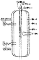
제 1 도는 본 발명의 제 1 실시예가 적용된 서스펜션의 일례를 도시한 평면도.1 is a plan view showing an example of a suspension to which the first embodiment of the present invention is applied.
제 2 도는 각각 제 3 도에 도시한 바와같은 특성을 얻기 위한 전후의 레터럴링크(lateral link)시스템의 변형특성의 예를 도시한 그래프.2 is a graph showing examples of deformation characteristics of a lateral link system before and after each of which obtains the characteristics as shown in FIG.
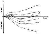
제 3 도는 본 발명에 의한 특성선의 예를 도시한 그래프.3 is a graph showing an example of a characteristic line according to the present invention.
제 4 도는 본 발명의 제 1 실시예에 의한 특성에 의거해서 후륜의 거동변화를 도시한 평면도.4 is a plan view showing the behavior change of the rear wheels based on the characteristics according to the first embodiment of the present invention.
제 5 도는 내측링크와 외측링크와의 결합부분을 도시한 확대단면도.5 is an enlarged cross-sectional view showing a coupling portion between the inner link and the outer link.
제 6 도는 부시의 일례를 도시한 것으로서 그 직경방향 단면도.6 shows an example of a bush, the cross-sectional view in the radial direction thereof.
제 7 도는 제 6 도의 Ⅶ-Ⅶ선 단면도.FIG. 7 is a cross-sectional view taken along line 6 of FIG.
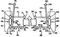
제 8 도는 본 발명의 제 2 실시예에 작용된 서스펜션의 일례를 도시한 평면도.8 is a plan view showing one example of the suspension acted on the second embodiment of the present invention.
제 9 도는 본 발명 제 2 실시예의 특성선의 예를 도시한 그래프.9 is a graph showing an example of the characteristic lines of the second embodiment of the present invention.
제 10 도는 본 발명의 제 2 실시예에 의한 특성에 의거해서 후륜의 거동변화를 도시한 평면도.10 is a plan view showing a change in the behavior of the rear wheels based on the characteristics according to the second embodiment of the present invention.
제 11 도는 제 2 도에 도시한 바와같은 특성을 얻기위한 전후의 래터럴 링크시스템의 변형 특성예를 도시한 그래프.FIG. 11 is a graph showing examples of deformation characteristics of the lateral link system before and after obtaining the characteristics as shown in FIG.
제 12 도는 내측링크와 외측링크와의 결합부분을 도시한 확대단면도.12 is an enlarged cross-sectional view showing a coupling portion between an inner link and an outer link.
제 13 도는 내측링크와 외측링크와의 결합부분을 도시한 다른 실시예의 확대단면도.Figure 13 is an enlarged cross-sectional view of another embodiment showing the engaging portion of the inner link and the outer link.
* 도면의 주요부분에 대한 부호의 설명* Explanation of symbols for main parts of the drawings
1 : 브조프레임 2R,2L : 서스펜션1:
3R,3L : 후륜 4R,4L : 앞쪽래터럴링크3R, 3L:
4R.1,5R.1 : 내측링크 4R.2,5R.2 : 외측링크4R.1,5R.1: Inner Link 4R.2,5R.2: Outer Link
4R.3,4R.3 : 결합부위 5R,5L : 뒤쪽래터럴링크4R.3,4R.3:
6R,6L : 허브 8R,8L : 앞쪽부시6R, 6L:
12R,12L : 앞쪽부시 10R,10L : 뒤쪽부시12R, 12L:
14R,14L : 뒤쪽부시 15R,15L : 스핀들(회전중심)14R, 14L:
41 : 실린더 41a : 스토퍼41: cylinder 41a: stopper
42 : 피스톤 45 : 스프링42: piston 45: spring
α1,βl: 절곡점 1 : 소정변위량α 1 , β l : Bending point 1: predetermined displacement
본 발명은 차륜의 토우제어(toe contro1)를 행하도록 만들어진 자동차의 서스펜션에 관한 것이다.The present invention relates to a suspension of an automobile made for toe control of a wheel.
최근, 자동차의 서스펜션에 있어서는, 차륜 특히 후륜 토우제어를 행하여, 주행상태에 따라서 차체가 바람직한 거동(擧動)을 나타내도록 의도한 것이 많아지고 있다.In recent years, in the suspension of automobiles, wheels, in particular, rear toe control is performed, and a lot of intentions are made for the vehicle body to exhibit desirable behavior in accordance with the running state.
이 후륜을 토우제어하는 것중에는, 후륜에 작용하는 횡력(橫力)과의 관계에 있어서, 횡력이 클때에는 작을때에 비해서, 횡력의 중대에 따른 후륜의 토우인(toe in)방향의 변화비율을 크게한 것이있다(일본국 특허공개 소화60-148708호 공보참조). 즉 후륜을 그 회전 중심을 경계로 해서 전후에 배설한 1쌍의 래터럴링크(lateral link)를 개재해서 차체에 상하동자재케 부착하고, 이 래터럴링크의 차체쪽 혹은 후륜쪽에 대한 연결부분에 개재되는 부시의 변형특성을, 앞쪽 래터럴링크와 뒤쪽 래터럴링크에서는 상위하도록 설정함으로서, 상술한 토우제어를 얻을 수 있도록 하고 있다. 이와같이 함으로서, 급선회시 혹은 고속주행에서의 차선병경시 등 횡력이 매우 커질때는, 후륜을 상대적으로 토우인방향으로 함으로서, 후륜의 그립력(grip force)을 높게하여 조종안정성(操縱安定性)을 향상시키면서, 횡력이 작을때, 즉 낮은속도 혹은 중간속도시에서의 선회성 또는 회두성(回頭性)이라고도 함 확보되게 된다. 그리고 이와같은 것에 있어서는, 횡력에 대한 차륜의 토우변화량을 나타내는 특성선이, 1개의 절곡점(특성변경점)을 가지도록 한 것이 된다.During the toe control of the rear wheels, in the relationship with the lateral force acting on the rear wheels, the ratio of change of the rear wheels in the toe in direction according to the lateral force is smaller than in the case of small lateral forces. (See Japanese Patent Application Laid-Open No. 60-148708). That is, the rear wheels are attached to the vehicle body vertically via a pair of lateral links disposed at the front and rear of the center of rotation of the rear wheels, and the bushes are interposed at the connection portion of the lateral links to the body side or the rear wheel side. The toe control described above can be obtained by setting the deformation characteristic of to be different between the front lateral link and the rear lateral link. In this way, when the lateral force becomes very large, such as when turning sharply or in a lane disease at high speeds, the rear wheels are relatively toe-inward, thereby increasing the grip force of the rear wheels and improving the steering stability. When the lateral force is small, that is, at low or medium speeds, it is also referred to as turning or migrating. And in such a thing, the characteristic line which shows the amount of tow change of a wheel with respect to a lateral force is made to have one bending point (characteristic change point).
상술한 바와같이, 횡력에 따라서 후륜을 토우제어하는 종래의 것에 있어서는, 횡력이 커질수록 조종안정성이 향상하는 방향 즉 토우인 방향으로 토우제어하는 것으로 되어있고, 이것은 또, 조종안정성의 확보가 직진안정성 확보에도 관련된다는 발상으로부터 이루어진 것이다. 즉, 직진안정성 및 조종안정성의 확보는모두 후륜을 상대적으로 토우인 시킴으로서 당해 후륜의 그립력을 높이고, 이 그립력이 높아지는 것에 의해서 차체를 구부러지지 않게 한다는 점에 있어서 공통이다.As described above, in the conventional tow control of the rear wheels in accordance with the lateral force, the tow control is performed in the direction in which the steering stability improves as the lateral force increases, that is, the toe-in direction, which further ensures the stability of the steering. It also comes from the idea of being related. In other words, securing straightness and steering stability are common in that the rear wheels are relatively toe to raise the grip force of the rear wheels, and the grip body is not bent to increase the grip force.
그러나, 상기 종래와 같이 횡력에 따라서 후륜의 토우제어를 행하였을 경우의 직진안정성, 특히 고속시의 직진안정성이 반드시 충분히 만족되지는 못하였다.However, the linear stability in the case of performing the toe control of the rear wheels in accordance with the lateral force as in the conventional art, in particular, the linear stability at high speed is not necessarily satisfactorily satisfied.
이 직진안정성이 충분히 만족되지 않는 원인을 추구하였던바, 급선회시 혹은 차선변경시와같이, 차체의 큰 거동변화를 수반해서 조종안정성 확보를 얻을려는 영역에서의 후륜에 작용하는 횡력은 연속해서 다만 고속직진주행을 행하고 있을때의 횡력의 크기와는 크게 떨어져서 존재하고 있다는 것을 알 수 있었다. 즉, 고속시의 직진 주행시에 있어서는, 후륜에 작용하는 횡력이 선회성이 요구된 때의 횡력의 크기보다도 더 작은영역에 있다는 것을 알 수 있었다.The reason for this is that the straightness stability is not satisfactorily satisfied.The lateral force acting on the rear wheels in the area to obtain steering stability along with the large change of the body, such as during sharp turn or lane change, is continuously high speed. It can be seen that they are far from the magnitude of the lateral force when driving straight. In other words, it was found that in the straight traveling at high speed, the lateral force acting on the rear wheel is in a region smaller than the magnitude of the lateral force at the time of turning capability required.
본 발명은 상기와 같은 사정을 감안해서 이루어진 것으로서, 횡력에 따라서 후륜을 토우제어 하는데 있어서, 종래와 같이 횡력이 비교적 작을때의 선회성 향상과 횡력이 비교적 클때의 조종안정성 확보를 행하면서고속직진주행을 행하도록 할때의 횡력이 매우 작을때의 직진안정성을 높일 수 있도록 한 자동차의 서스펜션을 제공하는데 있다.SUMMARY OF THE INVENTION The present invention has been made in view of the above circumstances, and in the tow control of the rear wheels according to the lateral force, as in the prior art, while improving the swingability when the lateral force is relatively small and securing the stability of the steering when the lateral force is relatively high It is to provide a suspension of a vehicle to improve the straightness stability when the lateral force when the operation is very small.
상술한 목적을 달성하기 위하여, 본 발명에서는 상술한 바와같이 직진안정성이 특히 요구되는 운정상태에서의 후륜에 작용하는 횡력이 선회성이 요구되는 운정상태에서의 후륜에 작용하는 횡력 보다도 작은점을 감안해서, 이 횡력의 크기에 의한 후륜의 토우제어를, 횡력이 작은 쪽에서 큰쪽의 순서로, 직진안정성을 위한 영역과, 선회성을 위한 영역과, 조정안정성을 위한 영역의 3개의 영역으로 나누어지도록 하고 있다. 구체적으로는 후륜이 그 회전중심을 경계로 해서 전후에 배치된 한쌍의 래터럴링크를 개재해서 차체에 상하동 자재케 지지되고, 이를 각 래터럴링크의 차체쪽 및 후륜쪽으로의 연결부분에 각각 부시가 개재되어서 이루어진 자동차의 서스펜션에 있어서, 상기 뒤쪽 래터럴 링크는 내측링크와 외측링크를 미리 압축이 부여된 스프링을 개재해서 이 스프링을 압축하는 방향으로 소정량만큼 상대변위 가능하게해서 결합함으로서 구성되고,각각 상기 부시를 포함하는 상기 앞쪽 래터럴 링크시스템과 뒤쪽 래터릴링크시스템과의 횡력에 대한 변형특성이 서로 다르게 설정되고, 상기 전후의 래터럴링크 시스템의 변형 특성의 상위에 의해서 횡력에 대해서의 후륜의 토우변화량을 나타낸 특성선이, 횡력이 작을때 및 횡력이 클때에는 횡력이 중간정도일 때에 비해서, 횡력의 증대에 따른 후륜의 토우인 방향으로의 변화비율이 커지도록 구성한 것이다.In order to achieve the above object, the present invention considers that the lateral force acting on the rear wheel in the driving state where straightness stability is particularly required as described above is smaller than the lateral force acting on the rear wheel in the driving state in which rotationality is required. Thus, the toe control of the rear wheels by the magnitude of the lateral force is divided into three areas, the area for straightness stability, the area for turning stability, and the area for adjustment stability, in the order from the smaller side to the larger side. have. Specifically, the rear wheels are supported up and down on the vehicle body via a pair of lateral links arranged in front and rear of the center of rotation, and the bushes are interposed in the connecting parts to the body and rear wheels of each lateral link. In the suspension of a vehicle made up, the rear lateral link is configured by coupling the inner link and the outer link by a predetermined amount in a direction in which the spring is compressed in a direction in which the spring is compressed, respectively, the bush The deformation characteristics of the lateral force between the front lateral link system and the rear lateral link system, which are different from each other, are set differently, and the tow variation of the rear wheel with respect to the lateral force is shown by the difference of the deformation characteristics of the front and rear lateral link systems. When the characteristic line is small when the lateral force is small and when the lateral force is medium when the lateral force is large On the contrary, the ratio of change of the rear wheels in the toe-in direction is increased as the lateral force increases.
이와같이 횡력에 대해서의 후륜의 토우변화량을 나타내는 특성선이 제 1 실시예에서는 1개의 절곡점만 있었던 것이 본 발명의 제 2 실시예에서는 2개의 절곡점을 가지므로, 횡력이 중간정도일 때에 선회성을 만족시키게 함으로서 횡력이 이것보다도 작은 영역 및 큰영역의 어느쪽에 있어서도 후륜의 그립력이 상대적으로 높아져서, 직진안정성 및 조종안정성을 얻을 수.있게 된다. 즉, 횡력이 작은쪽의 절곡점을 제1절곡점, 횡력이 큰쪽의 절곡점을 제2의 절곡점이라고 하면, 횡력의 증대에 따라서, 제1절곡점에 달할때까지의 횡력이 작을때는 직진안정성이 확보되는 토우제어 영역이 되고, 제1절곡점으로부터 제2절곡점까지의 횡력이 중간정도일때는 선회성이 확보되는 토우제어 영역이 되며, 제2절곡점 이후의 횡력이 클때에는 조종안정성이 확보되는 토우제어 영역이 된다.As described above, since the characteristic line representing the amount of change in the toe of the rear wheel with respect to the lateral force had only one bend point in the first embodiment, the second embodiment of the present invention had two bend points. By making it satisfy | fill, the rear wheel grip force becomes relatively high also in the area | region where the lateral force is smaller than this, and the linear stability and steering stability can be acquired. That is, if the bending point of the side with the smallest lateral force is called the first bending point and the bending point of the side with the larger lateral force is the second bending point, when the lateral force until the first bending point is small according to the increase of the lateral force, it is straight ahead. It becomes a tow control area that ensures stability, and when the lateral force from the first bend point to the second bend point is medium, it becomes a tow control area that secures turnability, and when the lateral force after the second bend point is large, the steering stability It becomes a toe control area secured.
더욱 구체적으로는, 선호성이 요구되는 횡력이 중간정도일때(예를들면 0.4∼0.5G)보다도, 직진안정성이 요구되는 횡력이 작을때(예를들면 0.2∼0.3G) 및 조종안정성이 요구되는 횡력이 클때(예를들면 0.5G이상)는, 횡력의 증대에 따른 후륜의 토우인방향으로의 변화비율이 크므로, 횡력이 중간정도일때의 선회성을 확보하면서, 직진안정성 및 조종안정성을 확보할 수 있다.More specifically, when the lateral force requiring straightness is small (for example 0.2 to 0.3G) and when the lateral force requiring preference is moderate (for example, 0.4 to 0.5G), the lateral force for steering stability is required. In this case (for example, 0.5G or more), since the ratio of change of the rear wheel to the toe-in direction due to the increase in the lateral force is large, the straightness and the steering stability can be secured while securing the turning ability when the lateral force is medium. have.
또, 본 발명에서는, 후륜의 각 래터럴 링크의 차체쪽 및 차륜쪽에 대한 연결부분에 개재되는 부시가 아닌뒤쪽 래터럴 링크의 중간부 즉 서로 소정량 만큼 상대변위 가능하게 한 내측링크와 외측링크와의 결합부분에 미리 압축된 압축상태로 별도 착설된 스프링을 이용함으로서 상술한 바와같은 토우제어를 위한 특성선의절곡점을 얻도록 하였으므로 환언하면, 주로 승차감 확보를 위하여 개재되는 상기 부시의 변형특성을 복잡하게 할 필요가 없도록 하고 있으므로, 토우제어를 위한 세팅이 용이하고 확실하게 행할 수 있어, 당해 세팅의 자유도도 높은 것이된다.In addition, in the present invention, the inner link and the outer link are coupled to the intermediate portion of the rear lateral link, that is, the predetermined amount of the rear link, rather than the bush, which is interposed between the lateral links of the rear wheels and the body parts of the rear wheels. In order to obtain the bending point of the characteristic line for the tow control as described above by using a spring installed separately in the compressed state in advance, in other words, the deformation characteristics of the bush interposed mainly to secure the riding comfort Since it is not necessary, the setting for toe control can be performed easily and reliably, and the freedom of the setting is also high.
또, 본 발명은, 차륜을 회전자재케 지지하는 차륜지지부재와, 상기 차륜지지부재를 차체에 대하여 상하동자재케 연결하며 대체로 차폭방향으로 뻗어서 차체의 전후방향으로 소정거리 이간되어 병설되며 또한 내측단부가 회동가능하게 착설되고 외측단부가 상기 차륜지지부재에 각각 회동가능하게 착설된 한쌍의 래터럴링크를 갖춘 자동차의 서스펜션에 있어서, 상기 한쌍의 래터럴링크의 적어도 한쪽은 도중에서 분할되어서 내측링크와 외측링크로 분리되고, 상기 내측링크와 외측링크 사이에는 그 연결측단부에 미리 압축력이 부여된 탄성부재가 개재되어서 링크축방향으로 또 내측링크 및 외측링크를 서로 근접하는 방향의 하중이 상기 미리압축된 압축력을 초과할때 상기 탄성부재가 변형함으로서 링크길이가 짧아지도록 구성한 것을 특징으로 하는 자동차의 서스펜션을 제공하는 것이다.In addition, the present invention, the wheel support member for supporting the wheels and the rotational support, and the wheel support member is connected vertically and vertically with respect to the vehicle body and generally extends in the vehicle width direction to be spaced apart by a predetermined distance in the front and rear direction of the vehicle body and the inner end A suspension of a vehicle having a pair of lateral links in which a pivot is mounted rotatably and an outer end is pivotally mounted on the wheel support member, wherein at least one of the pair of lateral links is divided in the middle so that the inner link and the outer link are separated. A compressive force is applied between the inner link and the outer link, and the load in the link axis direction and the direction in which the inner link and the outer link are close to each other is interposed between the inner side and the outer link. When the elastic member is deformed to exceed the link length characterized in that configured Is to provide the car's suspension.
또한 본 발명은 후륜이 그 회전중심을 경계로 해서 전후에 배치된 한쌍의 래터럴링크를 개재해서 차체에 상하동 자재케 지지되고, 이를 각 스티이링 링크의 차체쪽 및 후륜쪽으로의 연결부분에 각각 부시가 개재되어서 이루어진 자동차의 서스펜션에 있어서, 상기 뒤쪽 래터럴 링크는, 내측링크와 외측링크를 미리 입축력이 부여된 스프링을 개재해서 이 스프링을 압축하는 방향으로 소정량 만큼 상대변위 가능하게 하여 결합함으로서 구성되고, 각각 상기 부시를 포합하는 상기 앞쪽 래터럴링크 시스템과 뒤쪽 래터럴링크 시스템의 횡력에 대한 변형 특성이 서로 다르게 설정되고, 상기 전후의 래터럴링크 시스템의 변형 특성의 상위에 의해서, 횡력에 대해서의 후륜의 토우변화량을 표시하는 특성선이, 횡력이 작을때 및 횡력 클때에는 횡력이 중간 정도일때에 비해서, 횡력의 증대에 따른 후륜의 토우인 방향으로의 변화비율이 커지도록 되어있는 것을 특징으로 하고 있다.In addition, according to the present invention, the rear wheels are supported up and down on the vehicle body via a pair of lateral links disposed at the front and rear of the center of rotation thereof, and the bushes are connected to the vehicle body and rear wheels of each of the steering links, respectively. In the suspension of a vehicle interposed therebetween, the rear lateral link is configured by combining the inner link and the outer link by a predetermined amount relative to the predetermined direction in the direction in which the spring is compressed through a spring to which the axial force is applied. And the deformation characteristics of the lateral force of the front lateral link system and the rear lateral link system respectively including the bush are set differently, and the toe of the rear wheel with respect to the lateral force is different by the difference of the deformation characteristics of the front and rear lateral link systems. When the characteristic line indicating the amount of change is small and the lateral force is large, the lateral force is medium. Compared to the drawing, the change ratio in the toe-in direction of the rear wheels is increased according to the increase in the lateral force.
이하, 본 발명의 제 1 실시예에 대하여 첨부한 도면에 의거해서 설명한다.EMBODIMENT OF THE INVENTION Hereinafter, 1st Example of this invention is described based on attached drawing.
제 1 도는 FF차의 후륜에 본 발명의 제 1 실시예를 적용하였을 경우의 예를 도시한 개략적 도면으로서, 좌우후륜의 서스펜션과 모두 동일한 구조이므로, 이하의 설명에서는 오른쪽 후륜용의 서스펜션에 대해서 설명하기로 하고, 왼쪽후륜용 서스펜션에 대해서는 오른쪽 후륜용의 구성요소에 붙인「R」의 첨자대신에 「L」의 첨자를 사용하기로 하고, 그 중복된 설명은 생략한다.FIG. 1 is a schematic diagram showing an example in which the first embodiment of the present invention is applied to a rear wheel of an FF vehicle. Since the suspension structure of the right and left rear wheels is the same structure, the following description will be given of the suspension for the right rear wheel. For the left rear wheel suspension, the "L" subscript is used instead of the "R" subscript attached to the right rear wheel component, and the overlapping description is omitted.
이 제 1 도에 있어서, (1)은 스프링 상부의 중량으로서 차체에 고정된 보조프레임이고, 이 보조프레임(1)에는 요동아암식의 오른쪽 서스펜션(2R)을 개재해서, 오른쪽 후륜(3R)이 상하동 자재케 지지되어 있다.In FIG. 1,
상기 서스펜션(2R)은, 각각 차폭방향으로 뻗는 뒤쪽 래터럴링크(5R) 및 후술하는 바와같이 분할식으로된 앞쪽 래터럴링크(4R)와, 차체 전후방향으로 뻗는 휘일지지부재로서의 허브(6R)를 가지고 있다. 이 앞쪽 래터럴링크(4R)의 내측단부(차폭방향 내측단부)는, 보조프레임(1)에서 돌설한 지지축(7R)에 대해서 부시(8R)를 개재해서 회동자재케 연결되고, 뒤쪽 래터럴링크(5R)의 내측단부(차폭방향 내측단부)는 보조프레임(1)에서 돌설(突設)한 지지축(9R)에 대해서 부시(10R)를 개재해서 회동자재케 연결되어 있다. 또 앞쪽 래터럴링크(4R)의 외측단부는, 상기 허브(6R)의 진단부에 돌설한 지지축(11R)에 대하여 부시(12R)를 개재해서 회동자재케 연결되고, 뒤쪽 래터럴링크(5R)의 외측단부는, 이 허브(6R)후단부에서 돌설한 지지축(13R)에 대해서 부시(14R)을 개재해서 회동자재케 연결되어있다. 그리고, 허브(6R)외측단부에는 스핀들(15R)이 돌설되고, 오른쪽 후륜(3R)이 이 스핀들(l5R)을 중심으로 해서 회전자재케 지지되어 있다.The
상기 전후의 래터럴링크(4R)(5R)는 서로 거의 평행하게 배치되고, 그 각 외측단부의 부시(12R)(14R)와의 전후방향 중간부분에 스핀들(15R)이 배치되어 있다. 이렇게 함으로서, 후륜(3R)에 입력되는 횡력은, 전후의 래터럴링크(4R)(5R)에 거의 같게 등분되어서 입력된다. 또, 상기 지지축(7R)(9R)(11R)(13R) 및 부시(8R)(10R)(12R)(14R)는 각각 자체 전후방향으로 그 축심이 뻗어 있으므로, 오른쪽후륜(3R)은, 지지축(7R)(9R)을 중심으로 해서 상하방향으로 요동자재케 되어 있다. 그리고, 허브(6R)의 내측단부에서 돌설된 지지축(16R)에는 거의 차체전후 방향으로 뻗은 텐션로드(17R)의 후단부 슈우가 부시(18R)를 개재해서 회동자재케 연결되고, 이 텐션로드(17R)의 전단부는, 부시(19R)를 개재해서 차체에서 돌설한 지지축(20R)에회동자재케 연결되어 있다. 물론, 이 양부시(18R)(19R)는 차폭방향으로 뻗어있고, 상기 텐션로드(17R)에 의해서 허브(6R)의 전후방향의 강성이 확보되고 있다.The front and rear
또한, 허브(6R)에는, 이미 알려져 있는 바와같이 유압완충기와 탄성고무 또는 코일스프링으로 이루어진 지주(27R)의 하단부가 연결되어 있다.In addition, the
앞쪽 래터럴링크(4R)는 서로 별체로 형성된 내측링크(4R.1)와 외측링크(4R.2)후술하는 바와같이 결합함으로서 구성되고, 이 내외측링크(4R.1)(4R.2)와의 결합부위(4R.3)에는 후술하는 바와같이, 미리 압축된 스프링이 개재되어 있다. 그리고, 부시(8R)(12R)외에 상기 스프링을 포함하는 앞쪽 래터럴링크(4R)시스템의 변형특성을 제 2 도의(F)선우로, 또 부시(10R)(14R)를 포함하는 뒤쪽 래터럴링크(5R)시스템의 변형특성을 제 2 도의 (R)선으로 표시하고 있다.The front
상기 앞쪽 래터럴링크(4R)에 있어서의 결합부위(4R.3)의 상세한 도면을 제 5 도에 도시하고 있다.FIG. 5 shows a detailed view of the engaging portion 4R.3 in the front
제 5 도에서, 내측링크(4R.i)의 외측단부는, 차폭방향 바깥쪽으로 개구하는 실린더(41)가 일체형으로 형성되어있다. 또, 외측링크(4R.2)의 내측단부에는, 상기 실린더(4l)내에 접동자재케 감합된 큰 직경의 피스톤(42)가 일체로 형성되어있다. 이 피스톤(42) 즉 외측링크(4R.2)는 실린더(41)에 나사결합된 덮개부재(43)에 의해서, 탄성부재(44)를 개재해서 이탈을 방지하고, 즉 내측링크(4R.1)에 대해서 외측링크(4R.2)가 소정의 거리이상 떨어지는 것이 방지되고 있다. 또한, 실린더(41)내에 압축상태에서 배설한 스프링(45)(실시예에서는 코일스프링)에 의해서, 외측링크(4R.2)가 후륜(3R)쪽으로 향해서 부세되고 있다.In Fig. 5, the outer end of the inner link 4R.i is formed integrally with a
환언하면, 덮개부재(43)의 실린더(41)에 대한 나사결합 위치를 조정함으로서 스프링(45)의 압출력 즉 미리 압축되는 압축력이 조정되도록 되어있다. 이렇게함으로서, 앞쪽 래터럴링크(4R)를 압축시키도록 하는 외력에 대해서, 당초는 미리 압축된 스프링(45)에 의한 큰 힘에 대항하고, 외력이 미리 압축된 압축력 보다도 커지면, 스프링(45)이 그 탄성계수에 따른 형태로 압축(앞쪽 래터럴링크(4R)의 압축)되어 가게된다.In other words, by adjusting the screwing position of the
각 부시 (8R) (10R) (12R) (14R) 는 제 6 도, 제 7 도에 도시 한 바와같이, 지 지 축(7R) (9R) (11R) (13R)이 감합되는 내부통(21)과 전후의 래터럴링크(4R)(5R)가 결합되는 외부통(22)과, 이 내외부통(21)(22)사이에 감삽된 고무재(23)로 이루어지나, 이 고무재(23)는 소정의 경도로 설정되어 있다. 먼저, 래터럴링크(4R)(5R)의 외측단부의 부시(12R)(14R)는 서로 같은 경도를 가진 고무재(23)에 의해서 충만된 것으로 되어 있으므로,이 양부시(12R)(14R)에 있어서의 하중(횡력)과 그 변형량과의 관계는 서로 같게 되어있다. 앞쪽 래터럴링크(4R)내측단부에 있는 부시(8R)와 뒤쪽 래터럴링크(5R)내측단부에 있는 부시(10R)는, 앞쪽의 부시(8R)쪽이 뒤쪽의 부시(10R)보다도 딱딱한 것으로 되어있다.Each
이상과 같은 구성에 의해서, 앞쪽 래터럴 링크(4R)시스템의 하중(횡력)에 대한 변형특성은 제 2 도(F)선과 같이되며, 또 뒤쪽 래터럴링크(5R)시스템의 변형 특성은 제 2 도의 (R)선과 같이된다. 즉, 특성선(F)은, 하나의 절곡점(특성변경점)(α)을 가지고, 하중(횡력)이 (α)보다도 작아지는 범위내는 그 변형이 작아지고(딱딱함),(α)를 초과한 후에는 변형이 커지도록(유연해짐) 설정된다.According to the above configuration, the deformation characteristic of the front
또, 특성선(R)은 거의 선형인 것이 된다. 그리고, 실시예에서는 양특성선(F)(R)은 1점에서 서로 바뀌어 하중이 교점보다 작을때는 앞쪽 래터럴링크(4R)시스템의 변형량이 뒤쪽 래터럴링크(5R)시스템의 변형량 보다도 작아지고, 하중이.이 교점보다도 커지면, 앞쪽 래터럴링크(4R)시스템의 변형량이 뒤쪽 래터럴링크(5R)시스템의 변형량보다도 커진다. 물론, 절곡점(α)시점에서의 하중은 앞쪽 래터럴링크(4R)에 있어서의 스프링(45)의 미리 압축된 압축력에 상당한다. 또, 특성선(F)의 원점으로부터 절곡점(α)까지의 기울기는 부시(8R)의 특성에 의존한다.In addition, the characteristic line R becomes almost linear. In the embodiment, both characteristic lines F and R are interchanged at one point, and when the load is less than the intersection, the deformation amount of the front
상술한 전후의 래터럴링크(4R)(5R)시스템의 변형특성의 차이에 의해서 발생한다. 오른쪽 후륜(3R)에 작용하는 횡력의 크기에 대한 오른쪽 후륜(3R)의 토우변화량의 관계를 제 2 도의 특성선(C)으로 표시하고 있으며, 기타 본 발명에 의해서 얻는 특성선의 대표예를 (a)(b)(c)(d)(e)로 해서 도시하고 있다.This is caused by the difference in deformation characteristics of the
이 제 3 도에 도시한 특성선(C)에 의거해서 오른쪽 후륜(3R)의 거동(擧動)변화에 대해서, 제 4 도에 의해서 설명한다. 이 제 4 도에 있어서, 횡력을 (F)로 표시하고 있으며, 오른쪽 후륜(3R)의 자세변화를 횡력(F)이 「0」일때를 실선으로, 횡력(F)이 「작을」때를 2점쇄선으로 또한 횡력(F)이 「클」때를 파선으로 표시하고 있다. 또, 01∼04는, 오른쪽 후륜(3R)의 폭방향 중심선이고, 01이 횡력이 「0」일때를,02가 횡력 「작을」때를, 03가 횡력이 「클」때를 표시하고 있다. 또한, 스피링(45) 및 부시(8R)등은, 각각 모식적으로 스프링의 형상으로 표시하고 있다.Based on the characteristic line C shown in FIG. 3, the behavior change of the right
이 제 4 도로부터도 명백한 바와같이, 횡력(F)이 0일때는, 오른쪽 후륜(3R)은 똑바로 전방을 향하고 있다. 횡력(F)이 작을때는, 앞쪽 래터럴링크(4R)시스템의 변형량이 뒤쪽 래터럴링크(5R)시스템의 변형량 보다도 작기 때문에, 오른쪽 후륜(3R)은 토우아우트(toe out)하는 경향이 되어, 직진안정성과 조종성의 적절한 밸런스 유지가 가능하게 된다. 또 횡력(F)이 「클」때는, 앞쪽 래터럴링크(4R)시스템의 변형량보다도 뒤쪽 래터럴링크(5R)시스템의 변형량이 작으므로, 오른쪽 후륜(3R)은, 횡력(F)이 「작을」때보다도 토우인량이 증가되어 조종안정성의 향상을 도모할 수 있게 된다. 즉, 토우인량이 증대된다고 하는 것은, 토우인량의 「작을」때 보다도 인더스티어링 특성이 강해지게 된다. 물론, 상술한 것은 모두 왼쪽후륜(3L)에 대해서도 마찬가지이다.As is also apparent from this fourth figure, when the lateral force F is zero, the right
이상 실시예에 대해서 설명하였으나, 본 발명은 후륜구동차에 대해서도 마찬가지로 적용 할수 있다.Although the embodiment has been described above, the present invention can be similarly applied to a rear wheel drive vehicle.
또, 본 발명은, 전후의 래터럴링크를 가진 것이면, 적절한 형식의 서스펜션에 대해서 마찬가지로 적용할수 있다. 예를들면, 제 1 도에 있어서의 전후의 래터럴링크(4R)(5R)를 그 차폭방향 내측단부가 외측단부 보다도 넓게 한 것, 허브(6R)에 대해서 더욱 차폭방향으로 뻗은 상부아암(로드형상 혹은 A형의 것 등 그 형상은 문제삼지 않음)을 연결한 이른바 더블위시.본 타입(멀티링크식)의 것 등에 대해서도 마찬가지로 적용할수 있다. 상기 멀티링크식의 것에 있어서는, 차체전후 방향으로 뻗은 텐션로드(17R)(트레이 링크아암)를, 차폭방향의 강성을 작게 또한 상하방향의 강성이 높아지도록 패널형상으로 한것이어도 된다.In addition, the present invention can be similarly applied to a suspension of an appropriate type as long as it has lateral links before and after. For example, the
또한, 본 발명은 전륜에 대해서도 적용할 수 있으며, 이 경우는, 전후의 래터럴링크(4R)(5R)의 구성을 제 1 도에 도시한 것과 반대의 관계, 즉 뒤쪽 래터럴링크(5R)를 미리 압축된 스프링(45)를 가진 분할식으로 하면 된다. 물론 이경우는, 횡력에 대한 전륜의 토우변화량을 나타낸 특성선이, 제 3 도의 것과는 상하 대칭이 되도록 한 형상이 된다.The present invention can also be applied to the front wheels, in which case the configuration of the front and rear
본 발명은 이상 상술한 것으로부터 명백한 바와같이 횡력이 작을때의 직진안정성과 조종성을 적절히 밸런스를 유지시키면서, 횡력이 클때의 안정성 확보라는 2개의 조건을 만족하는 특성을 얻는 데에, 전후의 래터럴링크의 한쪽을 분할식으로 해서 이 분할부분에 개재되는 미리 압축된 스프링을 이용하도록 하고 있으므로, 각 래터럴링크의 차체쪽 혹은 차륜쪽으로의 연결부분에 착설된 부시의 변형특성을 특히 복잡하게 할 필요가 없으며, 부시를 소망의 특성과 같이 용이, 확실하게 착설할 수 있음과 동시에 착설의 자유도가 높은 것이 된다.As apparent from the foregoing, the present invention achieves a characteristic that satisfies the two conditions of securing stability when the lateral force is large while maintaining the balance of straightness stability and maneuverability when the lateral force is small. Since the one side of the cross section is divided into a pre-compressed spring interposed in the divided part, the deformation characteristics of the bush installed in the connection portion of the lateral link to the vehicle body side or the wheel side need not be particularly complicated. The bush can be installed easily and reliably like a desired characteristic and has a high degree of freedom for installation.
제 8 도는 FF차의 후륜에 본 발명의 제 2 실시예를 적용하였을 경우의 예를 도시한 개략적 도면으로서, 이제 8 도에서,(1)은 스프링상부의 중량으로서 차체에 고정된 보조프레임이고, 이 조보프레임(1)에는 요동아암식의 오른쪽 서스펜션(2R)을 개재해서, 오른쪽 후륜(3R)이 상하동 자재케 지지되어 있다.FIG. 8 is a schematic diagram showing an example in which the second embodiment of the present invention is applied to the rear wheel of an FF car, and in FIG. 8, (1) is an auxiliary frame fixed to the vehicle body as a weight on a spring part, The right
상기 서스펜션(R)은, 각각 차폭방향으로 뻗는 앞쪽 래터럴링크(4R) 및 후술하는 바와 같이 분할식으로된 뒤쪽래터럴링크(5R)와, 차체전후방향으로 뻗은 후회지지부재로서의 허브(6R)를 가지고 있다.The suspension R each has a front
이 앞쪽래터럴링크(4R)의 내측단부(차폭방향 내측단부)는, 보조프레임(1)에서 돌설한 지지축(7R)에 대해서 부시(8R)를 개재해서 회동자재케 연결되고, 뒤쪽 래터럴링크(5R)의 내측단부(차폭방향 내측단부)는 보조프레임(1)에서 돌설한 지지축(9R)에 대해서 부시(10R)를 개재해서 회동자재케 연결되어 있다. 또 앞쪽래터럴링크(4R)의 외측단부는, 상기 허브(6R)의 던단부에서 돌설한 지지축(11R)에 대해서 부시(12R)를 개재해서 회동자재케 연결되고, 뒤쪽 래터럴링크(5R)의 외측단부는, 이 허브(6R)후 탄부에서 돌설한 지지축(13R)에 대해서 부시(14R)를 개재해서 회동자재케 연결되어 있다. 그리고, 허브(6R)외측단부에는 스핀들(15R)이 돌설되고, 오른쪽 후륜(3R)이 이 스핀들(15R)을 중심으로 해서 회전자재케 지지되어 있다.The inner end portion (the vehicle width direction inner end portion) of the front
상기전후의 래터럴링크(4R)(5R)는 서로 거의 평행하게 배치되고, 그 각 외측단부의 부시(12R)(14R)와의전후방향 중간부분에 스핀들(15R)이 배치되어 있다. 이렇게함으로서, 후륜(3R)에 입력되는 횡력은, 전후의래터럴링크(4R)(5R)에 거의 같은 등분되어서 입력된다. 또, 상기 지지축(7R)(9R)(11R)(13R) 및 부시(8R)(10R)(12R)(14R)는 각각 차체 전후방향으로 그 축심이 뻗어 있으므로, 오른쪽 후륜(3R)은, 지지축(7R)(9R)을 중심으로 해서 상하방향으로 요동자재케 되어있다. 그리고, 허브(6R)내의 내측단부에서 돌설된 지지축(16R)에는 거의 차체전후 방향으로 뻗는 텐션로드(17R)에 의해서 허브(6R)의 전후방향의 강성이 확보되고 있다.The front and rear
또한, 허부(6R)에는, 이미 알려져 있는 바와같이 유압완충기와 탄성고무 또는 코일스피링으로 이루어진 지주(27R)의 하단부가 연결되어 있다.In addition, the lower end part of the support |
뒤쪽 래터럴링크(5R)는 서로 별체로 형성된 내측링크(5R.1)와 외측링크(5R.2)를 후술하는 바와같이 결합함으로서 구성되고, 이 내외측 링크(5R.1)(5R.2)와의 결합부위를 (5R.3)로서 표시하고있다.The
이 결합부위(5R.3)는 후술하는 바와같이, 미리 압축된 스프링이 개재되고 부시(8R)(12R)를 포함하는 앞쪽 래터럴링크(4)시스템의 변형특성을 제 11 도에(F)선으로, 또 부시(10R)(14R)의에 상기 스프링을 포함하는 뒤쪽 래터럴링크(5R)시스템의 변형특성을 제 11 도의 (R)선으로 표시하고 있다.This coupling portion 5R.3 shows the deformation characteristics of the front
상기 뒤쪽 래터럴링크(5R)에 있어서의 결합부의(5R.3)의 상세한 도면을 제 12 도에 도시하고 있다.FIG. 12 shows a detailed view of the engaging portion 5R.3 in the
먼저, 내측링크(5R.1)에는 그 외측단부에서 차폭방향 바깥쪽으로 개구하는 실린더(41)이 일체형으로 형성되어있다. 또, 외측링크(5R.2)의 내측단부에는 상기 실린더(41)내에 접동자재케 감합된 큰 직경의 피스톤(42)가 일체형으로 형성되어있다. 이 피스톤(42)즉 외측링크(5R.2)는 실린더(41)에 나사결합된 덮개부재(43)에 의해서, 탄성부재(44)를 개재해서 이탈을 방지하고, 즉 내측링크(5R.1)에 대해서 외측링크(5R.2)가 소정거리이상 떨어지는 것이 방지되고 있다.First, the inner side link 5R.1 is formed in one piece with a
또한, 실린더(41)내에서 압축된 상태로 배설한 스프링(45)(실시예에서는 코일스프링)에 의해서, 외측링크(5R.2)가 후륜(3R)쪽으로 향해서 부세되고 있다. 환언하면, 덮개부재(43)의 실린더(41)에 대한 나사 결합위치를 조정함으로서 스프링(45)의 압축력 즉 미리 압축되는 압축력이 조정되도록 되어있다.In addition, the outer link 5R. 2 is urged toward the
이렇게함으로서, 뒤쪽 래터럴링크(5R)를 압축시키도록 하는 외력에 대해서, 당초는 미리 압축된 스프링(45)에 의한 큰 힘으로 대항하고, 외력이 미리 압축된 압축력보다도 커지면, 스프링(45)이 그 탄성계수에 따른 형태로 압축[뒤쪽 래터럴링크(5R)의 압축]되어 가게된다.By doing so, the external force for compressing the
그리고, 스프링(45)이 압축되기 시작해서 외측링크(5R.2)가 소정변위량(l)만큼 내측링크(5R.1)에 대해서 상대변위하면, 피스톤(42)이 실린더(41)의 스토퍼(41a)에 당접하고, 이 당접후에는 뒤쪽 래터럴링크(5R)가 이 이상 압축되는 것이 규제된다.Then, when the
각 부시(8R)(10R)(12R)(14R)는 제 6 도 및 제 7 도에 도시한 바와같이, 지지축(7R)(9R)(11R)(13R)이 감합되는 내부통(21)과 래터럴링크(4R)(5R)가 결합되는 외부통(22)과, 이 내외부통(21)(22)사이에 감삽된 고무재(23)로 이루어지나, 이 고무재(23)는 소정의 경도로 설정되어 있다.Each
먼저, 래터럴링크(4R)(5R)의 외측단부의 부시(12R)(14R)는 서로 같은 경도로 가진 고무재(23)에 의해서 충만된 것으로 되어 있으므로, 이 양부시(12R)(14R)에 있어서의 하중(횡력)과 그 변형량과의 관계는 서로같게 되어있다. 앞쪽래터럴링크(4R)내측단부에 있는 부시(8R)와 뒤쪽래터럴링크(5R)내측단부에 있는 부시(10R)는, 앞쪽의 부시(8R)쪽이 뒤쪽의 부시(10R)보다도 유연한 것으로 되어있다.First, since the
상술한 바와같이 부시(8R)(10R)의 변형특성의 설정차이에 의해서, 또 스프링(45)을 개재하는 뒤쪽 래터럴링크(5R)의 구성에 의해서, 앞쪽 래터럴링크(4R)시스템의 하중(횡력)에 대한 변형특성은 제 11 도의(F)선과 같이되며, 또 뒤쪽 래터럴링크(5R)시스템 변형특성은 제 11 도의(R)선과 같이 된다. 즉, 특성선(R)은 2개의 절곡점(α1)(β)을 가지고, 하중(횡력)이(β1)보다도 작은 범위내는 그 변형이 작고(딱딱하고),(β1)을초과해서는 변형이 커지며(유연해지며), 또한(α1)을 초과하고 나서는 다시 변형이 작아지도록(딱딱하도록)설정된다. 또, 특성선(F)은 거의 선형의 것이된다. 그리고, 양 특성선(F)(R)은 r1과 r1과 r2의 2점에서 변하며, 하중이 Rr1보다 작을때 및 r2보다 클때는 앞쪽 래터럴링크(4R)시스템의 변형량이 뒤쪽 래터럴링크(5R)시스템의 변형량 보다도 커지게되고 하중이 r1과 r2사이에서는, 앞쪽 래터럴링크(4R)시스템의 변형량이 뒤쪽 래터럴링크(5R)시스템의 변형량 보다도 작게된다. 물론, 절곡점(β1)시점에서의 하중의 뒤쪽 래터럴링크(5R)에 있어서의 스프링(45)의 미리 압축된 압축력에 상당한다. 또 특성선(R)의 원점으로 부터 절곡점(β1)까지의 기울기 및 절곡점(α1)이후의 기울기는 부시(12R)(또는 14R)의 특성에 의존한다.As described above, the load (lateral force) of the front
상술한 전후의 래터럴링크(4R)(5R)시스템의 변형특성이 서로다름에 따라, 오른쪽후륜(3R)에 작용하는 횡력의 크기에 대한 오른쪽후륜(3R)의 토우변화량의 관계를 제 9 도에 특성선(X)으로 표시하고 있으며, 이제 9 도에 있어서의(α1)(β1)(γ1)(γ2)는 각각 제 3 도의 것과 대응하고 있다.As the deformation characteristics of the
이와같은 특성선(X)에 의거해서 오른쪽 후륜(3R)의 거동변화에 대해서 제 19-0 도에 의하여 설명한다.이 제 10 도에 있어서, 횡력을 F로 표시하고 있고, 오른쪽후륜(3R)의 자세변화를, 횡력(F)이 「0」일때를 실선으로, 횡력 (F) 이 「작을」때를 1점쇄선으로, 횡력 (F) 이 「중간」일때를 2점쇄선으로, 또한 횡력(F)이 「클」때를 파선으로 표시하고 있다. 또, 01∼04는 오른쪽 후륜(3R)의 축방향 중심선이며, 01은 횡력이 「0」일때를 02는 횡력이「작을」때를, 03는 횡력이「중간」일때를, 04는 횡력이 「클」때를 표시하고 있다.Based on such characteristic line X, the behavior change of the right
또한 부시(8R)(10R)는, 각각 모식적으로 스프링의 형상으로 표시하고 있으며, 제 2 실시예에서는 이 부시(8R)(10R)에 대해서, 횡력(F)이 균등하게 작용하도록 각 부재의 치수를 설정하고 있다.In addition,
이 제 10 도로부터 명백한 바와같이 횡력(F)이 0일때는, 오른쪽 후륜(3R)은 똑바로 전방을 향하고 있다.횡력(F)이 작을때는, 앞쪽래터럴링크(4R)시스템의 변형량이 뒤쪽 래터럴링크(5R)시스템의 변형량 보다도 크므로 오른쪽 후륜(3R)은 토우인이 되어, 직진안정성이 확보된다. 또, 횡력(F)이 「중간」일때는, 앞쪽 래터럴링크(4R)시스템의 변형량 보다도 뒤쪽 래터럴링크(5R)시스템의 변형량 쪽이 크므로, 오른쪽 후륜(3R)은, 횡력(F)이 작을때보다 토우인량이 완화(경감)되어 회두성 즉 조종성의 향상을 도모할 수 있게 된다.As is apparent from FIG. 10, when the lateral force F is zero, the right
즉, 토우인량이 완화된다고하는 것은, 토우인량이「클」때 보다도 언더스티어링 특성이 약해지게되어, 핸들의 꺽임에 대한 자동차의 방향추종성이 양호해진다. 또한 횡력이 「클」때는, 오른쪽후륜(3R)은 다시 토우인방향으로 변위되어, 급선회시나 고속차선변경시와 같은 때의 언더스티어링 경향을 강하게, 조종안정성이 확보된다.That is to say, the tow lifting is alleviated, the understeering characteristic is weaker than when the tow lifting is "large", and the direction of the vehicle to bend the steering wheel is improved. In addition, when the lateral force is "large", the right
물론 상술한 것은 모두 왼쪽후륜(3L)에 대해서도 마찬가지이다.Of course, the above is also true for the left
여기에서, 횡력(F)에 대한 후륜(3R)(또는 3L)의 토우변화량을 표시한 특성선(X)은, 제 9 도에 파선으로표시한 바와같이, 차종등에 따라서 여러가지 변형할 수 있는 것이며, 그 2개의 절곡점을 각각 검은 점으로표시하고 있다. 이를 파선으로 표시한 특성선에 있어서도, 횡력의 증대에 따른 토우인 방향으로의 변화비율(토우아우트는 부의토우인이라고 볼 수 있음)은 2개의 절곡점 사이에서 다른 부분보다도 작게 되어있다.Here, the characteristic line X which shows the tow change amount of the
제 13 도는 내측링크(5R.1)와 외측링크(5R.2)의 결합부분(5R.3)의 다른실시예를 도시한 도면으로서, 제 1 및 제 2 실시예와 그 동작은 마찬가지이므로, 그 설명을 생략한다. 다만 여기에서는 제 1 및 제 2 실시예의 코일스프링(45)대신에 탄성고무(53)를 사용하고 있으며, 실린더는 실린더케이스(51)와 캡(52)으로 구성되고, 또한 실린더 케이스(51)와 캡(52) 그리고 피스톤(42)사이에는 두개로 분리된 수지부시(54)가 개재되어서 구성된 점이다.FIG. 13 is a view showing another embodiment of the engaging portion 5R.3 of the inner link 5R.1 and the outer link 5R.2, and its operation is the same as that of the first and second embodiments. The description is omitted. In this case, however, the
이상 제 2 실시예에 대하여 설명하였으나, 본 발명은 후륜구동차에 대해서도 마찬가지로 적용할 수 있다. 또, 본 발명은, 전후의 래터럴 링크를 가진 것이면, 적절한 형식의 서스펜션에 대해서 마찬가지로 적용할수 있다. 예를들면, 제 8 도에 있어서의 전후의 래터럴링크(4R)(5R)를 그 차폭방향 내측단부가 외측단부보다도 넓게한 것, 허브(6R)에 대해서 더욱 차폭방향으로 뻗은 상부아암(로드형상 혹은 A형의 것등 그 형상은 문제삼지 않음)을 연결한 이른바 더블위시 본 타입(멀티링크식)의 것 등에 대해서도 마찬가지로 적용할 수 있다.Although the second embodiment has been described above, the present invention can be similarly applied to a rear wheel drive vehicle. In addition, the present invention can be similarly applied to a suspension of an appropriate type as long as it has lateral links before and after. For example, the front and rear
상기 멀티링크식의 것에 있어서는, 차체전후 방향으로 뻗은 텐션로드(17R)(트레이링크아암)를, 차폭방향의 강성을 작게 또한 상하방향의 강성이 높아지도록 패널형상으로 한 것이어도 된다.In the multi-link system, the
본 발명은, 이상 상술한 것으로부터 명백한 바와같이 횡력이 작을때의 직진안정성확보, 횡력이 중간정도일 때의 회두성확보, 횡력이 클때의 조종안정성 확보라는 3개의 조건을 모두 만족하는 주행상태에 따라서차량의 거동을 최적한 것으로 할 수 있다.According to the present invention, as is apparent from the above description, the driving stability satisfies all three conditions: securing straight stability when the lateral force is small, securing frosting when the lateral force is medium, and securing steering stability when the lateral force is large. The behavior of the vehicle can be made optimal.
또, 상기 3개의 조건을 만족하는 특성을 얻는데에 뒤쪽 래터럴 링크를 분할식으로 해서 이 분할부분에 개재되는 미리 압축된 스프링을 이용하도록 하고 있으므로, 각 래터럴링크의 차체쪽 혹은 후륜쪽으로의 연결부분에 착설된 부시의 변형특성을 특히 복잡한 것으로 할 필요가 없고, 소망의 특성과 같이 용이, 확실하게 세팅할 수 있음과 동시에 세팅의 자유도도 높은 것이 된다.In order to obtain the characteristic satisfying the above three conditions, the rear lateral link is used as a split type so that a pre-compressed spring interposed in this divided part is used. It is not necessary to make the deformation | transformation characteristic of the mounted bush especially complicated, and it can be set easily and surely like a desired characteristic, and also has high freedom of setting.
특허청구범위에 기재된 본 발명 각구성요소의 해당도면 부호는 오른쪽(R)구성요소의 부호만 기재하고,그 기능이 오른쪽구성요소와 동일한 왼쪽(L)구성요소의 부호는 편의상 기재하지 않는다.Corresponding reference numerals of the components of the present invention described in the claims describe only the symbols of the right (R) component, and the symbols of the left (L) component whose function is the same as the right component are not described for convenience.
Claims (16)
Applications Claiming Priority (9)
| Application Number | Priority Date | Filing Date | Title |
|---|---|---|---|
| JPP4746 | 1986-04-25 | ||
| JP9474286A JPH0694243B2 (en) | 1986-04-25 | 1986-04-25 | Car suspension |
| JP94746 | 1986-04-25 | ||
| JP9474686A JPH0694247B2 (en) | 1986-04-25 | 1986-04-25 | Car suspension |
| JPP4741 | 1986-04-25 | ||
| JP94742 | 1986-04-25 | ||
| JPP4742 | 1986-04-25 | ||
| JP9474186A JPH0694242B2 (en) | 1986-04-25 | 1986-04-25 | Car suspension |
| JP94741 | 1986-04-25 |
Publications (2)
| Publication Number | Publication Date |
|---|---|
| KR870009872A KR870009872A (en) | 1987-11-30 |
| KR900004352B1 true KR900004352B1 (en) | 1990-06-23 |
Family
ID=27307628
Family Applications (1)
| Application Number | Title | Priority Date | Filing Date |
|---|---|---|---|
| KR1019870003983A KR900004352B1 (en) | 1986-04-25 | 1987-04-25 | Vehicle suspension system |
Country Status (3)
| Country | Link |
|---|---|
| US (1) | US4729578A (en) |
| KR (1) | KR900004352B1 (en) |
| DE (1) | DE3713787A1 (en) |
Families Citing this family (7)
| Publication number | Priority date | Publication date | Assignee | Title |
|---|---|---|---|---|
| JP2825808B2 (en) * | 1986-10-31 | 1998-11-18 | マツダ株式会社 | Car rear suspension device |
| IT1217427B (en) * | 1988-04-18 | 1990-03-22 | Alfa Lancia Ind | VEHICLE SUSPENSION ARMS LENGTH ADJUSTMENT DEVICE |
| US4989894A (en) * | 1989-10-30 | 1991-02-05 | Chrysler Corporation | Independent rear suspension |
| US6000706A (en) * | 1996-05-14 | 1999-12-14 | Chrysler Corporation | Independent suspension for a vehicle axle with leading lower control arm geometry |
| US7175062B2 (en) | 2001-06-19 | 2007-02-13 | Kitaru Innovations Inc. | Hand-held tape dispenser having brake and flexible side |
| JP4319217B2 (en) * | 2006-12-27 | 2009-08-26 | 本田技研工業株式会社 | Telescopic actuator |
| DE102014113261B4 (en) | 2014-09-15 | 2017-04-27 | Benteler Automobiltechnik Gmbh | Automotive rear axle with elastic bearing |
Family Cites Families (12)
| Publication number | Priority date | Publication date | Assignee | Title |
|---|---|---|---|---|
| US3083032A (en) * | 1961-08-02 | 1963-03-26 | Ford Motor Co | Automotive suspension system |
| DE2627847C3 (en) * | 1976-06-22 | 1982-11-25 | Dr.Ing.H.C. F. Porsche Ag, 7000 Stuttgart | Front suspension for automobiles |
| JPS59966Y2 (en) * | 1978-09-14 | 1984-01-12 | マツダ株式会社 | Automotive rear wheel suspension system |
| JPS5876315A (en) * | 1981-10-29 | 1983-05-09 | Mazda Motor Corp | Strut type suspension for car |
| JPS58114932U (en) * | 1982-01-30 | 1983-08-05 | トヨタ自動車株式会社 | Vehicle suspension bushing structure |
| JPS58209605A (en) * | 1982-05-31 | 1983-12-06 | Mazda Motor Corp | Rear suspension for car |
| JPS58214470A (en) * | 1982-06-07 | 1983-12-13 | Nissan Motor Co Ltd | Rear wheel steering device |
| JPS60148707A (en) * | 1984-01-13 | 1985-08-06 | Mazda Motor Corp | Automobile's suspension |
| JPS60148708A (en) * | 1984-01-13 | 1985-08-06 | Mazda Motor Corp | Automobile's suspension |
| US4621830A (en) * | 1984-01-13 | 1986-11-11 | Mazda Motor Corporation | Automotive suspension system |
| JPS60161262A (en) * | 1984-01-31 | 1985-08-22 | Nissan Motor Co Ltd | Rear-wheel steering apparatus |
| US4588205A (en) * | 1984-09-21 | 1986-05-13 | Allied Corporation | Brake system |
-
1987
- 1987-04-24 US US07/042,447 patent/US4729578A/en not_active Expired - Fee Related
- 1987-04-24 DE DE19873713787 patent/DE3713787A1/en active Granted
- 1987-04-25 KR KR1019870003983A patent/KR900004352B1/en not_active IP Right Cessation
Also Published As
| Publication number | Publication date |
|---|---|
| US4729578A (en) | 1988-03-08 |
| KR870009872A (en) | 1987-11-30 |
| DE3713787A1 (en) | 1987-10-29 |
| DE3713787C2 (en) | 1992-02-13 |
Similar Documents
| Publication | Publication Date | Title |
|---|---|---|
| KR900005030B1 (en) | Vehicle suspension system having toe direction control means | |
| US4840396A (en) | Rear suspension system for automobiles | |
| KR100319580B1 (en) | Front suspension | |
| JPH0450166Y2 (en) | ||
| JPS6226921B2 (en) | ||
| US4621830A (en) | Automotive suspension system | |
| KR950003580B1 (en) | Wheel suspension of vehicle having combination of inverse a-type arm and i-type arm | |
| KR900004352B1 (en) | Vehicle suspension system | |
| US4632423A (en) | Structure for mounting stabilizer in vehicle suspension | |
| US4326734A (en) | Rear axle for motor vehicles | |
| JP3122728B2 (en) | Automotive wheel suspension | |
| KR910007519B1 (en) | Rear suspension apparatus for automobile vehicles | |
| KR100462242B1 (en) | torsion beam suspension | |
| KR101448796B1 (en) | Suspension system for vehicles | |
| JPS60148707A (en) | Automobile's suspension | |
| JP3105073B2 (en) | Vehicle suspension device | |
| JPH0694248B2 (en) | Car suspension | |
| JPH0313364Y2 (en) | ||
| JPH0694243B2 (en) | Car suspension | |
| JPH0694247B2 (en) | Car suspension | |
| JPH0694245B2 (en) | Car suspension | |
| JPH02283509A (en) | Macpherson strut type suspension | |
| JPH0299415A (en) | Suspension device for vehicle | |
| JPH085289B2 (en) | Car suspension | |
| JPH0694244B2 (en) | Car suspension |
Legal Events
| Date | Code | Title | Description |
|---|---|---|---|
| A201 | Request for examination | ||
| E902 | Notification of reason for refusal | ||
| G160 | Decision to publish patent application | ||
| E701 | Decision to grant or registration of patent right | ||
| GRNT | Written decision to grant | ||
| FPAY | Annual fee payment |
Payment date: 19970617 Year of fee payment: 8 |
|
| LAPS | Lapse due to unpaid annual fee |