KR900001843B1 - Apparatus for continuous processing in the directions of x and y - coordinates - Google Patents
Apparatus for continuous processing in the directions of x and y - coordinates Download PDFInfo
- Publication number
- KR900001843B1 KR900001843B1 KR1019860005795A KR860005795A KR900001843B1 KR 900001843 B1 KR900001843 B1 KR 900001843B1 KR 1019860005795 A KR1019860005795 A KR 1019860005795A KR 860005795 A KR860005795 A KR 860005795A KR 900001843 B1 KR900001843 B1 KR 900001843B1
- Authority
- KR
- South Korea
- Prior art keywords
- pair
- heat source
- heat
- pairs
- continuous processing
- Prior art date
Links
- 238000012545 processing Methods 0.000 title claims description 58
- 238000011282 treatment Methods 0.000 claims description 37
- 230000033001 locomotion Effects 0.000 claims description 17
- 239000011521 glass Substances 0.000 claims description 12
- 230000004888 barrier function Effects 0.000 claims description 8
- 230000009194 climbing Effects 0.000 claims 2
- 230000000903 blocking effect Effects 0.000 claims 1
- 230000008878 coupling Effects 0.000 claims 1
- 238000010168 coupling process Methods 0.000 claims 1
- 238000005859 coupling reaction Methods 0.000 claims 1
- 230000005855 radiation Effects 0.000 claims 1
- 239000011347 resin Substances 0.000 claims 1
- 229920005989 resin Polymers 0.000 claims 1
- 230000000630 rising effect Effects 0.000 claims 1
- 238000005476 soldering Methods 0.000 abstract description 28
- XEEYBQQBJWHFJM-UHFFFAOYSA-N Iron Chemical compound [Fe] XEEYBQQBJWHFJM-UHFFFAOYSA-N 0.000 description 16
- 239000004065 semiconductor Substances 0.000 description 13
- 239000000758 substrate Substances 0.000 description 11
- 229910052742 iron Inorganic materials 0.000 description 8
- 238000001816 cooling Methods 0.000 description 7
- 238000010438 heat treatment Methods 0.000 description 5
- 230000005540 biological transmission Effects 0.000 description 4
- 238000010586 diagram Methods 0.000 description 3
- 230000001678 irradiating effect Effects 0.000 description 3
- 238000000034 method Methods 0.000 description 3
- 230000008569 process Effects 0.000 description 3
- 229910000679 solder Inorganic materials 0.000 description 3
- 230000008859 change Effects 0.000 description 2
- 239000000356 contaminant Substances 0.000 description 2
- 230000007547 defect Effects 0.000 description 2
- 239000013307 optical fiber Substances 0.000 description 2
- RZVAJINKPMORJF-UHFFFAOYSA-N Acetaminophen Chemical compound CC(=O)NC1=CC=C(O)C=C1 RZVAJINKPMORJF-UHFFFAOYSA-N 0.000 description 1
- VYPSYNLAJGMNEJ-UHFFFAOYSA-N Silicium dioxide Chemical compound O=[Si]=O VYPSYNLAJGMNEJ-UHFFFAOYSA-N 0.000 description 1
- 238000013459 approach Methods 0.000 description 1
- 238000005452 bending Methods 0.000 description 1
- 230000017525 heat dissipation Effects 0.000 description 1
- 238000003780 insertion Methods 0.000 description 1
- 230000037431 insertion Effects 0.000 description 1
- WABPQHHGFIMREM-UHFFFAOYSA-N lead(0) Chemical compound [Pb] WABPQHHGFIMREM-UHFFFAOYSA-N 0.000 description 1
- 239000000155 melt Substances 0.000 description 1
- 239000002184 metal Substances 0.000 description 1
- 229910052751 metal Inorganic materials 0.000 description 1
- 230000003287 optical effect Effects 0.000 description 1
- 238000003825 pressing Methods 0.000 description 1
- 239000005297 pyrex Substances 0.000 description 1
- 230000009467 reduction Effects 0.000 description 1
- 238000011160 research Methods 0.000 description 1
- 229910052709 silver Inorganic materials 0.000 description 1
- 239000004332 silver Substances 0.000 description 1
- 230000007480 spreading Effects 0.000 description 1
- XLYOFNOQVPJJNP-UHFFFAOYSA-N water Substances O XLYOFNOQVPJJNP-UHFFFAOYSA-N 0.000 description 1
Images


Classifications
-
- H—ELECTRICITY
- H05—ELECTRIC TECHNIQUES NOT OTHERWISE PROVIDED FOR
- H05K—PRINTED CIRCUITS; CASINGS OR CONSTRUCTIONAL DETAILS OF ELECTRIC APPARATUS; MANUFACTURE OF ASSEMBLAGES OF ELECTRICAL COMPONENTS
- H05K3/00—Apparatus or processes for manufacturing printed circuits
- H05K3/30—Assembling printed circuits with electric components, e.g. with resistor
- H05K3/32—Assembling printed circuits with electric components, e.g. with resistor electrically connecting electric components or wires to printed circuits
- H05K3/34—Assembling printed circuits with electric components, e.g. with resistor electrically connecting electric components or wires to printed circuits by soldering
-
- H—ELECTRICITY
- H05—ELECTRIC TECHNIQUES NOT OTHERWISE PROVIDED FOR
- H05K—PRINTED CIRCUITS; CASINGS OR CONSTRUCTIONAL DETAILS OF ELECTRIC APPARATUS; MANUFACTURE OF ASSEMBLAGES OF ELECTRICAL COMPONENTS
- H05K13/00—Apparatus or processes specially adapted for manufacturing or adjusting assemblages of electric components
- H05K13/04—Mounting of components, e.g. of leadless components
- H05K13/046—Surface mounting
- H05K13/0465—Surface mounting by soldering
-
- B—PERFORMING OPERATIONS; TRANSPORTING
- B23—MACHINE TOOLS; METAL-WORKING NOT OTHERWISE PROVIDED FOR
- B23K—SOLDERING OR UNSOLDERING; WELDING; CLADDING OR PLATING BY SOLDERING OR WELDING; CUTTING BY APPLYING HEAT LOCALLY, e.g. FLAME CUTTING; WORKING BY LASER BEAM
- B23K1/00—Soldering, e.g. brazing, or unsoldering
- B23K1/005—Soldering by means of radiant energy
-
- H—ELECTRICITY
- H05—ELECTRIC TECHNIQUES NOT OTHERWISE PROVIDED FOR
- H05K—PRINTED CIRCUITS; CASINGS OR CONSTRUCTIONAL DETAILS OF ELECTRIC APPARATUS; MANUFACTURE OF ASSEMBLAGES OF ELECTRICAL COMPONENTS
- H05K13/00—Apparatus or processes specially adapted for manufacturing or adjusting assemblages of electric components
- H05K13/04—Mounting of components, e.g. of leadless components
Landscapes
- Engineering & Computer Science (AREA)
- Manufacturing & Machinery (AREA)
- Microelectronics & Electronic Packaging (AREA)
- Mechanical Engineering (AREA)
- Electric Connection Of Electric Components To Printed Circuits (AREA)
- Electrical Discharge Machining, Electrochemical Machining, And Combined Machining (AREA)
Abstract
Description
제1도는 납접처리를 위한, 기판위 IC-칩 배열예의 도식적인 평면도.1 is a schematic plan view of an IC-chip arrangement on a substrate for soldering.
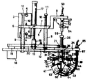
제2도는 본 발명에 의한 장치 실시예의 정면도.2 is a front view of a device embodiment according to the present invention.
제3도는 제2도에 보인 장치의 측면도.3 is a side view of the device shown in FIG.
제4도는 제2도에 보인 장치의 저면도.4 is a bottom view of the device shown in FIG.
제5도는 제2도에 보인 장치의 열선원(熱線源) 조립체의 회전축의 수직 단면도.FIG. 5 is a vertical sectional view of the axis of rotation of the heat source assembly of the apparatus shown in FIG.
제6도는 열선원 조립체의 미끄럼 부재 일단부의 확대 수직 단면도.6 is an enlarged vertical cross-sectional view of one end of the sliding member of the heat source assembly.
제7a도는 열선 비임의 촛점이 납접 선상에 모아지는 것을 보이는 개략도.Figure 7a is a schematic diagram showing the focus of the hot wire beams gathered on the lead line.
제7b도는 선 촛점 쌍의 최소간격과 중심칼라 외경과의 관계로써 그 외경을 결정하기 위한 도표.FIG. 7B is a chart for determining the outer diameter as a relation between the minimum distance of the line focus pair and the outer diameter of the central color.
제8도는 열선 조사용 차폐기구의 구조도.8 is a structural diagram of a shield for radiating heat rays.
제9도는 열선원의 단면도.9 is a sectional view of a heat source.
제10도는 차폐부재의 사시도.10 is a perspective view of a shield member.
제11도는 열선원의 측면도.11 is a side view of a heat source.
제12도는 차폐 폭 조정 방식을 보이는, 차폐요소의 부분 단면도.12 is a partial cross-sectional view of the shielding element showing the shielding width adjustment scheme.
제13도는 열선원 조립체가 선회요소에 의해 90°만큼 선회된, 제2도에 보인 장치의 저면도이다.FIG. 13 is a bottom view of the apparatus shown in FIG. 2 with the heat source assembly pivoted 90 ° by the pivot element.
* 도면의 주요부분에 대한 부호의 설명* Explanation of symbols for main parts of the drawings
1 : 기판 2 : 반도체 소자1
1a, 1b, 2a, 2b: 단자 리이드핀 3 : 수직지지부1 a , 1 b , 2 a , 2 b : terminal lead pin 3: vertical support part
4, 6 : 보울트 5 : 브래키드4, 6: Bolt 5: Breaked
7, 8 : 지지부 9 : 안내슬리이브7, 8: support portion 9: guide sleeve
10 : 안내봉 11 : 스토퍼10: guide rod 11: stopper
12 : 호울더 테이블 13 : 연결 러그(lug)12 holder table 13 connection lug
14, 26 : 피스톤 로드 15 : 분할 생크(shank)14, 26: piston rod 15: split shank
16 : 연결핀 17 : 실린더/피스톤 장치16: connecting pin 17: cylinder / piston device
18 : 구동수단 19, 20 : 벨트/풀리전동수단18: drive means 19, 20: belt / pulley transmission means
22 : 회전축 24 : 상부지지판22: rotating shaft 24: upper support plate
25 : 실린더/피스톤작동기 27 : 연결부재25: cylinder / piston actuator 27: connecting member
28, 29, 35, 36 : 링크(link) 30, 37 : 연결핀28, 29, 35, 36: link 30, 37: connection pin
31, 32 : 피봇 조인트 33, 34 : 미끄럼 부재31, 32:
38, 39 : 안내봉 40 : 하부지지판38, 39: guide rod 40: lower support plate
43, 44 : 아암 45, 46 : 피봇조인트43, 44:
47, 48 : 열선원 49 : 실린더/피스톤 유니트47, 48: heat source 49: cylinder / piston unit
50 : 파이프 51 : 피스톤 로드50: pipe 51: piston rod
52 : 연결부품 53 : 연결부재52: connecting part 53: connecting member
54 : 공기 파이프 55 : 저지 튜우브54: air pipe 55: jersey tubing
56 : 관통구멍 57 : 튜우브 단부56 through hole 57: tubing end
59 : 안내튜우브 60 : 중심칼라59: guide tube 60: center color
61, 62 : 열선비임 63, 64 : 열선램프61, 62:
65 : 내열유리 덮개판 66, 67 : 반사 측판65: heat-resistant
68, 69 : 수용부 70 : 지지 프레임68, 69: receiving portion 70: support frame
71 : 스토퍼 72, 73 : 차폐부재71: stopper 72, 73: shielding member
74, 75 : 차폐공간 76, 77 : 스토퍼 블록74, 75: shielded
78, 79 : 안내 바아 80, 81 : 고정핀78, 79:
82, 83 : 동력 전달 와이어 84, 85 : 실린더/피스톤유니트82, 83:
86, 87 : 피스톤 로드 88, 89 : 스토퍼 나사86, 87:
본 발명은 X 및 Y축 방향 연속 처리 장치에 관한 것으로, 특히 처리될 한쌍의 평행한 선형 단면들 즉, 처리선들 사이의 거리와 그 처리선들의 길이가 X 및 Y축 방향으로 서로 다른 경우에 있어서 IC칩 , LSI칩 등과 같은 반도체 소자의 가공물을 기판위에 납접하기에 특히 적합한 장치에 관한 것이다.The present invention relates to a continuous processing apparatus in the X and Y axis directions, in particular in the case where the pair of parallel linear sections to be processed, i.e., the distance between the processing lines and the length of the processing lines are different from each other in the X and Y axis directions. A device particularly suitable for soldering a workpiece of a semiconductor device such as an IC chip, an LSI chip, etc. onto a substrate.
IC 및 LSI칩과 같은 반도체 소자의 단자 핀들을 기판의 단자 핀들에 납접하는데 있어서는, 반도체 칩의 각 리이드(lead)핀을 기판의 해당 리이드 핀에 납접하기 위해 납접의 소요위치상에 점 조사를 실현시키는데 신축성 및 전도 필라멘트 즉 광섬유를 통해 전달된 레이저 비임이 채용되는 비접촉식 납접장치와, 그리고 납접인두를 납접의 소요위치에 직접시켜 납접을 달성하는 접촉식 납접장치가 실제로 사용되어 왔었다.In soldering the terminal pins of semiconductor devices such as IC and LSI chips to the terminal pins of the board, point irradiation is realized on the required position of the solder to solder each lead pin of the semiconductor chip to the corresponding lead pin of the board. Non-contact soldering devices employing flexible and conductive filaments, ie laser beams transmitted through optical fibers, and contact soldering devices which achieve soldering by directing the soldering iron to the required position of the soldering iron have been used.
상술한 비접촉식 납접장치는, 광섬유등과 같은 고가의 광학적 요소체와 장치들이 필요하기 때문에 시설비용이 많이 소요된다. 레이저 비임에 의한 납접은 점의 조사이기 때문에 레이저 비임의 조사에서 기인하는 고은에 의해 처리 작업도중 기판을 태우거나 반도체 칩을 파손하는 사고를 종종 유발한다.The non-contact soldering apparatus described above requires a lot of facility costs because of the necessity of expensive optical elements and devices such as optical fibers and the like. Since soldering by the laser beam is irradiation of a point, an accident which burns a substrate or damages a semiconductor chip during processing operation by the silver which originates from irradiation of a laser beam is often caused.
인두를 사용하는 접촉식 납접장치는, 납접인두 등에 부착되는 용융제 등의 오염물때문에 처리된 위치의 납접연결부에 종종 결함을 유래한다. 따라서 납접과정에서는 반드시 오염물을 제거하고 납접 인두의 끝을 자주 닦아 주어야 하는 번거로움이 있다. 특히, 처리될 반도체 칩의 형식과 형태가 변경됨에 따라 납접 인두의 끝 부분을 바꾸거나 교체 해야 할 필요가 있으며, 따라서 여러가지 형식의 납접 인두끝을 준비해 두어야 하는 번거로움이 있다. 또한 접촉식 장치의 경우에, 처리선들 사이의 거리나 처리선들의 길이가 X 및 Y축 방향으로 서로 다를때 X 및 Y축 방향으로의 연속적 처리가 불가능하다. 왜냐하면 인두끝이 각각의 처리 위치와 반드시 접촉해야 하기 때문이다.Contact soldering devices that use a soldering iron often result in defects in the solder joints in the treated position due to contaminants such as melts attached to the soldering iron and the like. Therefore, during the soldering process, it is necessary to remove contaminants and to clean the tip of the soldering iron frequently. In particular, as the type and shape of the semiconductor chip to be processed change, it is necessary to change or replace the end of the soldering iron, and therefore, it is troublesome to prepare various types of soldering iron tips. Also in the case of the contact apparatus, continuous processing in the X and Y axis directions is impossible when the distance between the processing lines or the length of the processing lines are different from each other in the X and Y axis directions. This is because the tip of the iron must be in contact with each treatment position.
본 발명인은 경제적인 방식으로 연결 결함의 발생을 배제 하면서도 높은 처리 성능을 이룰수 있는 장치의 개발을 위해 광범위한 연구를 수행했으며, 접촉식 납접에 비해 비접촉식 납접으로 더욱 깨끗하고 효율적인 작업을 수행할 수 있다는 것을 고려한 결과 본 발명에 도달하게 되었다.The inventors have conducted extensive research to develop devices that can achieve high throughput while eliminating the occurrence of connection defects in an economical manner, and that they can perform cleaner and more efficient work with contactless soldering than contact soldering. Consideration has led to the present invention.
본 발명의 목적은, 한쌍의 평행한 처리선 사이의 거리와 그 처리선들의 길이가 X 및 Y축 방향으로 다른 경우에도 X 및 Y축 방향 모두로 연속적이고 계속적인 납접이 가능한, 가공물의 연속 처리 장치를 제공하는 것이다.An object of the present invention is a continuous treatment of a workpiece, which enables continuous and continuous soldering in both the X and Y axis directions even when the distance between the pair of parallel treatment lines and the length of the processing lines are different in the X and Y axis directions. To provide a device.
본 발명의 다른 목적은, 열선비임이 처리선의 길이에 해당하는 길이를 가진 선분 형태의 지속 촛점(이하 선촛점이라 칭함)식으로 처리선상에 집중되기 때문에 처리선외의 다른 부분에 열선의 과도한 조사가 되지 않는, X 및 Y축 방향 연속 처리 장치를 제공하는 것이다.Another object of the present invention is that the heating beam is concentrated on the treatment line in the form of a continuous focus in the form of a line segment having a length corresponding to the length of the treatment line (hereinafter referred to as a line focus), so that excessive irradiation of the heating wire is applied to other parts of the treatment line. It is an object of the present invention to provide an X and Y axis direction continuous processing apparatus.
본 발명의 또다른 목적은, Y축 방향으로의 해당 쌍의 처리 선들을 조사하는 열선비임의 한쌍의 선촛점들 사이의 거리와 선촛점의 길이가, X축 방향 처리의 종료후 Y축 방향 처리 개시까지의 시간동안 자동으로 조정되기 때문에 X 및 Y축방향 모두에 실시된 완전한 1주기의 총 처리시간이 감소될 수 있는, X 및 Y축 방향으로의 가공물 연속 처리 장치를 제공하는 것이다.It is still another object of the present invention that the distance between the pair of prefocals of the hot wire beam irradiating the pair of process lines in the Y-axis direction and the length of the prefocus are Y-axis direction treatments after the completion of the X-axis direction processing. It is to provide an apparatus for continuously processing a workpiece in the X and Y axis directions, since the total processing time of one complete cycle performed in both the X and Y axis directions can be reduced because it is automatically adjusted during the time up to the start.
본 발명에 따른 장치에 있어, 서로에 대하여 여러가지 간격으로 기판상에 배치된 IC나 LSI칩과 같은 가공물 위에서 X축이나 Y축 방향으로 평행하게 연장하는 여러가지 길이의 처리선들을 동시에 조사하기 위한 한쌍의 열선원들이 마련된다.In the apparatus according to the present invention, a pair of pairs for simultaneously irradiating processing lines of various lengths extending in parallel in the X-axis or Y-axis directions on a workpiece such as an IC or an LSI chip disposed on a substrate at various intervals with respect to each other. Heat sources are provided.
열선원 쌍은, X축 방향으로 연장하는 처리선들의 처리, 예를 들어 납접후에 Y축 방향 처리를 자동으로 계속하기 위해 직각 선회가 가능하도록 배열된 연선원 조립체상에 조립되어 있다. 따라서, 한쌍의 처리선의 X축 방향 납접이 한쌍의 열선 비임에 의해 우선 수행되는데, 한쌍의 열선비임 각각은, 처리선 즉 반도체 칩의 단자 리이드 핀 열과 기판위의 해당 단자 리이드 핀 열이 정렬되는 소정 길이의 납접 선상에 촛점이 맞추어지며, 그 후 Y축 방향으로의 한쌍의 처리선에 대한 납접이 열선원 조립체를 90°만큼 선회시킴으로써 실시된다. 선촛점 쌍사이의 거리와 처리선 쌍사이의 거리를 X축 방향뿐만 아니라 Y축 방향으로도 일치시키기 위해, 상기 열선원 쌍은 처리선 각각을 향해 일정한 자세를 유지한 채, 즉 처리선을 향하는 각도를 일정하게 유지한채 형행 이동된다.The heat source pair is assembled on a stranded source assembly arranged to enable a right angle turn to automatically continue processing of the processing lines extending in the X-axis direction, for example, Y-axis processing after soldering. Therefore, the X-axis soldering of a pair of processing lines is first performed by a pair of hot wire beams, each of which is a predetermined line in which a processing line, that is, a terminal lead pin row of a semiconductor chip and a corresponding terminal lead pin row on a substrate are aligned. Focusing on the lead wire of length is followed by soldering the pair of treatment lines in the Y-axis direction by pivoting the heat source assembly by 90 °. In order to match the distance between the pairs of prefocus and the pair of treatment lines not only in the X-axis direction but also in the Y-axis direction, the pair of heat source lines maintain a constant posture toward each of the treatment lines, i.e., toward the treatment line. It moves around with the angle held constant.
한편 X방향과 Y방향 처리를 위한 처리선을 조사하는 선촛점의 길이조정은, 한쌍의 차폐 부재가 그의 자동적인 미끄럼 운동이 가능하도록 열선원의 각 열선 방출 구멍상에 배치되는 방식으로 달성된다. 따라서 처리될 가공물의 X 및 Y방향 처리 길이가 다른때에도, 선 촛점 쌍사이의 거리 뿐만 아니라 각 촛점 선의 길이에 있어서 선촛점의 자동 조정이 이루어질 수 있다. 그러므로, 가공물에 대한 크기와 형태의 제한이 가해지지 않으며 X 및 Y방향에서 실현된 처리 단계들을 포함한 완전한 1주기의 처리 작업에 필요한 총처리 시간의 감소가 이루어진다. 따라서 작업 성능이 현저하게 개선된다. 열선원 조립체를 90°선회시켜 X방향 처리 단계에서 Y방향 처리 단계로 자동으로 계속함으로써, 작업대위에 일단 적절한 위치로 배치된 가공물을 X 및 Y방향 모두로 연속적인 방식으로 자동 처리될 수 있다.On the other hand, the length adjustment of the prefocus for irradiating the treatment line for the X-direction and the Y-direction processing is achieved in such a manner that a pair of shield members are disposed on each heat ray emitting hole of the heat source so as to enable automatic sliding movement thereof. Thus, even when the X and Y direction treatment lengths of the workpiece to be treated are different, automatic adjustment of the prefocus in the length of each focal line as well as the distance between the prefocus pairs can be made. Therefore, no limitations on the size and shape of the workpiece are imposed, and a reduction in the total processing time required for one complete cycle of processing operations including the processing steps realized in the X and Y directions is achieved. Thus, the performance of work is significantly improved. By turning the heat source assembly 90 ° and automatically continuing from the X-direction processing step to the Y-direction processing step, the workpiece once placed on the work platform once in the proper position can be automatically processed in a continuous manner in both the X and Y directions.
이하 첨부된 도면들을 참조하여 본 발명의 실시예에 대하여 더욱 상세하게 기술한다.Hereinafter, exemplary embodiments of the present invention will be described in detail with reference to the accompanying drawings.
첨부된 도면에, 본 발명에 따른 장치의 구체적인 실시예가 예시되고 있다. 본 발명이 예시된 실시예에 의하여 어떠한 경우에 있어서도 제한받지 않는다는 것을 알아야 한다.In the accompanying drawings, specific embodiments of the device according to the invention are illustrated. It should be understood that the present invention is not limited in any case by the illustrated embodiments.
제1도 납접 처리를 위한, 기판위 IC나 LSI칩과 같은 반도체 소자(2)의 배열을 개략적으로 보이는 평면도이다. 반도체 칩(2)의 둘레에는 기판(1)의 해당 단자 리이드 핀들(2a), (2b)에 정렬된 다수의 단자 리이드 핀들(1a), (1b)이 마련되어 있다. 이같이 배열된채 유지되는 가공물은 도시되지 않은 작업대 위의 노트(not)상에 배치된다. 제1도의 실시예에서, x축 방향으로 연장하는 2개의 평행한 처리선들의 간격 L1과 Y축 방향으로 연장하는 2개의 평행한 처리선들의 간격 L2사이의 관계는 L1〈L2이다. 따라서, 한쌍의 X축 방향 처리 선들은, 서로로부터 L1만큼 떨어져 있으며 길이 11인 선 촛점식으로 해당 처리 선상 각각에 촛점이 맞추어진 한쌍의 해당 열선 비임에 의해 조사된다. 유사한 방식으로, Y축 방향 처리는, 처리선의 길이에 해당하는 길이 12를 가지며 서로에 대하여 간격 L2를 유지하는 선 촛점식으로 Y방향으로 연장하는 해당 쌍의 처리 선상에 촛점이 맞추어진 한쌍의 열선 비임에 의해 수행된다. 상기 방식으로 처리를 실현할 수 있는 장치의 실시예에 대하여 이하 기술한다.FIG. 1 is a plan view schematically showing the arrangement of a
제2도는 본 발명에 의한 장치의 실시예의 정면도이다. 장치의 수직 지지부(3)가 고정 보울트(4), 4)로 장치에 고정되어 있다. 브래키트(5)가 수직 지지부(3)의 일측에 (제3도에서 왼측) 보울트(6), (6)로 일체로 부착되어 있다. 브래키트(5)는 긴 지지부(7)와 짧은 지지부(8)를 지닌다. 긴 지지부(7)의 아래측에는 고정 안내 슬리이브들(9), (9)이 있는데, 예를 들어 안내 슬리이브들의 상단부가 그 아래측에서 나사로 죄어져 있다. 안내 슬리이브의 안에는 각각의 안내봉(10)이 위, 아래로 움직일 수 있도록 삽입되어 있다. 각각의 안내봉(10) 위끝에 스토퍼(11)가 있다. 안내봉(10)의 하단부는 호울더 테이블(12)상에서 지지된다. 연결 러그(lug)(13)는 호울더 테이블(12)의 윗면에 배열되며, 실린더/피스톤 장치(17)의 피스톤 로드(14)와 분할 생크(15)를 연결핀(16)으로 연결하는 것을 돕는다. 피스톤 로드(14)는 유압 내지 공압으로 작동되는 실린더/피스톤 장치(17)에 의해 상하운동을 수행한다. 호울더 테이블(20)은 공기 회전 작동기와 같은 것으로 구성된 구동 수단을 운반한다.2 is a front view of an embodiment of the device according to the invention. The
구동 수단(18)의 구동력은 벨트/풀리 전동수단(19,20)에 의해 회전축(22)으로 전달된다. 회전축(22)은 호울더 테이블(12)안에 배치된 베어링 구멍(23)안에 회전 가능하게 삽입된 채 유지된다. 회전축(22)의 상단부에는 상부지지판(24)이 마련되어 있는데, 이 지지판 위에서 유압 내지 공압으로 작동되는 실린더/피스톤 작동기(25)가 해당 처리선 쌍위로 조사되는 선 촛점 쌍의 간격 조정을 실시한다. 실린더/피스톤 작동기(25)의 피스톤 로드(26)가 연결 부재(27)에 연결되어 있으며, 이 연결 부재(27)는 2개의 링크(28), (29)와 연결핀(3)으로 구성된 링크 연결부에 연결되어 있다. 각 링크들(28), (29)의 다른쪽은 피봇 조인트(31), (32)에 의해 한쌍의 미끄럼 부재(33), (34)의 다른쪽은 2개의 링크(35), (36)와 연결핀(37)으로 구성된 링크 연결부에 의해 더 연결되어 있다.The driving force of the drive means 18 is transmitted to the
미끄럼 부재 쌍(33), (34)의 끝부분들은 한쌍의 안내봉들(38), (39)위에서 미끄러질 수 있게 안내된다. 한쌍의 안내봉(28), (39)은, 회전축(22)의 하단부에 설치된 하부지지판(40)을 통하여 평행하게 고정 배치되어 있다. 미끄럼부재쌍(33), (34) 각각의 아래측에는 아암(43), (44)이 마련되어 있다. 아암들(43), (44)은 피봇조인트(45), (46)를 통하여 각각의 열선원(47),(48)을 운반한다.The ends of the sliding member pairs 33 and 34 are guided to slide on the pair of
브래키트(5)의 짧은 지지부(8)는, 유압이나 공압으로 작동되며, 예를 들어 파이프(50)를 통해 공기원(源)(도시안됨)에 연결된 실린더/피스톤 유니트(49)를 운반한다. 실린더/피스톤 유니트의 피스톤 로드(51)는 연결부품(52)으로 연결부재(53)에 연결되어 있다. 연결부재(53)의 일측에 공기 파이프(54)가 연결되어 있는데, 이 공기 파이프를 통하여 예를 들어 냉각 공기원(도시안됨)으로 부터 냉각 공기가 공급된다. 연결부재(53)의 상단부에는 저지튜우브(55)가 더 연결되어 있다. 저지튜우브(55)는 예를들어 금속 튜우브로 되어 있으며, 회전축(22) 중앙에 배치된 관통구멍(56)을 지나 자유롭게 미끄러질 수 있도록 가공물 근처까지 연장한다. 저지튜우브(55)의 하단부는 냉각 공기의 방출을 위하여 자유롭게 개방되어 있다. 냉각 공기의 균등한 방출을 위하여 적절하게 일정한 원주방향 분포로 튜우브 단부(57)둘레에, 많은 슬릿(slit)을 형성할 수 있다.The
회전축(22)의 하단부에는 안내튜우브(59)가 안으로 삽입되는 나사구멍(58)(제5도)이 있다. 저지튜우브(55)는 안내 튜우브(59)를 자유로이 움직일 수 있게 관통하도록 배치된다. 안내튜우브(59)의 하단부에는 열선원쌍(47), (48)의 열선램프(63), (64)에서 방출되는 열선비임(61), (62)의 선촛점 쌍사이의 최소간격을 유지하는 기능을 하는 중심칼라(60)가 착탈 가능하게 부착되어 있다. 그러므로 각각의 개별적인 처리 작입에 따른 임의의 용도를 위하여 여러가지 외경을 가진 다양한 크기의 중심칼라(60)들이 예비된다. 그러므로 본 발명에 따른 장치를 실제로 응용하는데 있어, 우선 열선비임의 선촛점 쌍사이의 거리가 X축 방향으로의 처리선 쌍사이의 거리 L1과 일치하도록 하며, 제7도에 주어진 상호관계 도료를 읽어 적당한 중심칼라(60)를 쉽게 선정할 수 있다.At the lower end of the
예를 들어, 만약 처리선 쌍사이의 거리 L1이 15mm라고 가정하면, 적당한 중심 칼라(60)의 외경 Φ는 11.8mm이어야 한다.For example, if the distance L 1 between the pairs of treatment lines is 15 mm, the outer diameter φ of the
Y축 방향으로의 처리선 쌍사이의 거리 L2를 정하기 위해 하부 지지판(40)에 설치된 지지부재(60b)안에 있는 나사의 이동 행정을 조정할 수 있도로 설치된 조정나사(60a)를 조정하여 Y축 방향 처리선 쌍사이의 거리 L2를 조정한다. 조정 나사(60a)는 링크(35)와 (36)을 연결하는(37)의 바로 아래에 위치하고 있다. (제6도). 링크들(35), (36)의 하부 모서리가 조정 나사(60a)의 상부에 접하기 때문에 미끄럼 부재쌍(33), (34)의 수평 상호 이동을 제한함으로써 열선원쌍(47), (48)의 최대 간격을 제한한다. 따라서, 열선 비임의 선 촛점쌍 사이의 거리를 Y축 처리선 쌍사이의 거리 L2에 일치시킬 수 있다.Y to adjust the
열선원(4 : ),(48)의 일선 방축 구멍(제8,9도) 각각에는 열선램프(63), (64)와, 쿠오오트(quart)유리나 피렉스( pyrex, 상표)등과 같은 내열성 유리로된 유리덮개판(65)이 마련되어 있다. 내열 유리판(65)은, 반사 측판(66), (67)의 일부분을 구부려서 열선원의 그 반사측판의 하단부에 형성된 수용성(68), (69)를 따라 분리가능하게 삽입되어 있다.Each of the heat dissipation holes (8, 9) of the heat source (4 :), (48) has heat resistance such as heat lamps (63), (64) and quartz glass or pyrex (trade mark). A
유리판은 2개의 수용부들(68)중 하나의 밀면에서 유리판의 전폭을 걸쳐 연장하는 지지프레임(70)상에 지지되고 있다.The glass plate is supported on a
지지프레임(70)의 입구측 단부는 유리판(65)의 삽입을 용이하게 하기 위해 하방으로 약간 굽어져 있다.(제9도). 이렇게 삽입된 유리판(65)이 빠지지 못하도록, 유리판은 열선원 몸체상에 배치된 수직 미끄럼 스토퍼(71)에 의해 보유된다. 열선원들(47)과 (48)의 구조가 동일하기 때문에 이하 열선원(47)에 대해서만 설명한다.The inlet end of the
열선 비임의 길이 방향 연장을 제한함으로써 선 촛점의 길이를 제한하기 위해, 내열 유리판(65)을 따라서 미끄러질 수 있도록 유리판(65)의 외측면상에 배치된 한쌍의 차폐부재들(72), (73)로 구성된 차폐 요소가 열선원에 마련되어 있다. (제8도). 각각의 열선원은 한쌍의 차폐 부재들(72), (73)을 지니는데, 각각의 차폐 부재들은 열선 차폐 공간(74), (75)을 형성 하도록 차폐 부재를 둘러 싸는 원주상상승 장벽들(72a), (73a)을 가진다.A pair of
열선원안에 집적된 열의 방출을 용이하게 하기 위해 포위장벽(72a) 일부가 잘려져 있다(72b).A portion of the enclosing
열선원 쌍(47), (48)이 서로에 대하여 거의 최소 간격으로 위치하더라 (제2도), 포위 장벽들(72a), (73b)과 저지 튜우브(55)의 실질적인 접촉을 방지하기 위해 길이 방향 장벽들은 경사지게 형성된다.(제10도). 차폐부재쌍(72), (73) 각각에는 스토퍼 블록(76), (77)이 마련되어 있다(제8,10도).The heat source pairs 47 and 48 are located at substantially minimum intervals relative to each other (FIG. 2) to prevent substantial contact between the enclosing
안내 바아(78), (79)가 이 스토퍼 블록(76), (77)을 통해 삽입된다. 안내 바아(78), (79)는 고정판 (80), (81)을 미끄러질 수 있도록 관통한다. 스토퍼 블록(76), (77)은 신축성 작동 전달 와이어(82), (83)와 결합되며, 이 와이어의 다른끝은 공압으로 작동되는 실린더/피스톤 유니트(84), (85)의 피스톤 로드(86), (87)에 연결되어 있다.Guide bars 78, 79 are inserted through these stopper blocks 76, 77. The guide bars 78 and 79 penetrate the fixed
실린더/피스톤 유니트(84)는 차폐 부재(72)와 관련되어 있으며, 실린더/피스톤 유니트(85)는 차폐 부재(73)와 관련되어 있다. (제2도). 각각의 차폐 부재에는 스토퍼 나사(88), (89)가 더 마련되어 있는데, 이 나사들은 차폐 부재(72), (73)에 붙어 차폐 부재의 이동을 제한하는 작용을 한다.The cylinder /
스토퍼 나사들(88), (89)의 이동 행정이 작도록 선정되더라도 차폐부재쌍 (72), (73)의 이동량은 커지며, 따라서 더 긴 열선 비임의 선 촛점이 얻어진다. 그러므로 X축 방향 처리 길이(11)가 간단한 방식으로 더 길게 조정될 수 있다.Even if the movement stroke of the stopper screws 88, 89 is selected to be small, the amount of movement of the shielding pairs 72, 73 becomes large, thus obtaining a line focus of a longer hot wire beam. Therefore, the X-axis direction processing length 1 1 can be adjusted longer in a simple manner.
유사한 방식으로, 스토퍼 나사의 이동 행정을 상당히 더 크게 설정하므로써 Y축 방향 처리 길이(12)를 더 짧게 조정할 수 있다.In a similar manner, the Y-axis processing length 1 2 can be adjusted shorter by setting the travel stroke of the stopper screw considerably larger.
본 발명에 따른 장치의 실제 작동 방식은 다음과 같다.The actual mode of operation of the device according to the invention is as follows.
반도체 칩의 각 단자 리이드 핀이 기판의 해당 단자 리이드핀에 정렬되도록 반도체의 각 단자 리이드 핀열(1a), (1b)은 기판(1)위의 해당 단자 리이드 핀 열(2a), (2b)에 정렬된다.Each of the terminal lead pin rows 1a, 1b of the semiconductor is aligned with the corresponding terminal
그다음 열선 비임의 선 촛점 쌍의 거리와 선 촛점의 길이가 처리 선 쌍의 거리와 길이(L11, 및 L2,12)에 일치 하도록 조정된다. 만약에 예를 들어, X축 방향 처리선 쌍사이의 거리(L1)가 19mm라고 가정한다면, 제7도의 상호관계 도표로부터 중심 칼라(60)의 외경 는Φ 13.5mm이어야 한다.The distance of the line focus pair and the length of the line focus of the hot wire beam are then adjusted to match the distance and length L 1 1, and L 2 , 1 2 of the treatment line pair. If, for example, the distance L 1 between pairs of X-axis processing lines is 19 mm, the outer diameter of the
이 중심 칼라(60)가 안내 튜우브(59)의 하단부에 장착된다.This
열선원 쌍(47), (48) 각각은, 열선원의 측면 모서리가 중심 칼라(60)의 측면과 접할 때까지 피봇 조인트(45) 또는 (46)을 중심으로 기울어진다.Each of the heat source pairs 47, 48 is tilted about the pivot joint 45 or 46 until the side edges of the heat source come into contact with the side of the
이같은 방식으로, 열선원 쌍(47), (48)에서 방출되는 열선 비임(61), (62)의 평행한 선 촛점 쌍의 간격이 X축 방향의 평행한 처리 선 쌍사이의 거리와 일치하게 된다.In this manner, the spacing of the parallel line focus pairs of the heat ray beams 61 and 62 emitted from the heat ray source pairs 47 and 48 is equal to the distance between the parallel treatment line pairs in the X-axis direction. do.
그후, 선 촛점의 길이가 X방향 처리 길이와 일치하도록 조정하기 위해, 차폐 부재(72), (73)의 이동량에 상응하여 스토퍼 나사(88), (89)의 이동 행정이 설정된다.Then, in order to adjust the length of the line focus to match the X-direction processing length, the movement strokes of the stopper screws 88 and 89 are set corresponding to the movement amounts of the
선 촛점 쌍사이의 거리가 Y방향 처리 선 쌍사이의 거리(L2)에 일치하도록 조정하는데 있어 조정 나사(70a)의 이동 행정은, 링크들(28), (29)의 관절식으로 벌어지는 운동을 제한하므로써 열선 비임(61), (62)의 선 촛점 쌍사이의 거리와 처리 선쌍사이의 상기 거리(L2)의 일치를 이루기 위해 링크들(35), (36)의 해당 접촉 위치를 조정하도록 상응하여 설정된다.In adjusting the distance between the line focus pairs to match the distance L 2 between the Y-direction processing line pairs, the movement stroke of the adjusting
유사하게, Y축 방향 처리 길이(12)의 조정을 달성하는데 있어, 스토퍼 나사(88), (89)의 이동 행정은, 열선방출 구멍 폭을 적절하게 조정함으로써 선 촛점이 Y축 방향으로의 요구되는 처리길이(12)에 해당하는 적당한 길이에 도달하도록 상응하여 설정된다Similarly, in achieving the adjustment of the Y-axis direction treatment length 1 2 , the movement strokes of the stopper screws 88 and 89 are performed by appropriately adjusting the heat-radiation hole width so that the line focus is in the Y-axis direction. Correspondingly set to reach a suitable length corresponding to the required processing length 1 2
반도체 칩을 기판위에 납접하는데 있어, 공압 실린더/피스톤 유니트(49)는 저지 튜우브(55)의 하단부가 가공물을 적당한 상태로 누르면서 잡도록 반도체 칩(2)의 중심에 접촉될 때까지 저지 튜우브(55)를 하강시키도록 작동된다. 실린더/피스톤 장치(17)는, 열선 램프(63), (64)에서 나온 열선 비임(61), (62)의 촛점이 처리 길이 11과 간격 L1을 지니고 X축 방향으로 평행하게 연장하는 처리 선 쌍위로 해당 길이와 간격을 가진 한쌍의 선 촛점 형식으로 모아지는 위치까지 열선원 조립체를 하강시키기 위해 피스톤 로드(14)가 내려가도록 작동된다, 납접은 처리 선위로 촛점이 모아진 상기 열선 비임 쌍으로 처리 선들을 조사하므로써 수행된다.In soldering a semiconductor chip onto a substrate, the pneumatic cylinder /
X축 방향으로의 처리가 마무리된 후, 냉각 공기가 저지 튜우브(55)를 통하여 가공물의 윗면으로 공급된다. 이와 동시에 호울더 테이블(12)은 실린더/피스톤 장치(17)를 작동 하므로써 상승되고, 그 다음 선회 요소를 작동하므로써 열선원 조립체는 90°선회된다.After the treatment in the X-axis direction is finished, cooling air is supplied to the upper surface of the workpiece through the
이같이 벨트(20)를 통하여 조립체의 직각 선회를 야기하기 위해 풀리 수단(19), (21)을 회전시키도록 구동수단(18)이 가동된다. 선 촛점 쌍 사이의 거리가 처리선 쌍사이의 거리(L2)와 일치하도록 조정하기 위해, 실린더,피스톤 작동이(25)는, 미끄럼부재들(33), (34)이 서로에 대하여 반대 방향으로 평행 이동하도록 미끄럼 부재를 안내봉(38), (39)상에서 링크들(28), (29)을 통해 미끄러지게 하기 위해 피스톤 로드(26)를 돌출시키도록 가동된다.In this way, the drive means 18 is actuated to rotate the pulley means 19, 21 to cause orthogonal pivoting of the assembly through the
이같은 벌림 운동은 링크들(28), (29)과 조정나사(60a)의 접촉 때문에 제한되며, 그로 인하여 처리 선 쌍사이의 거리(L2)에 해당하는 선 촛점 쌍사이의 거리가 설정된다.This spreading motion is limited due to the contact of the
처리 길이(12)를 조정하기 위해 상부 지지판위에 배치된 실린더/피스톤 유니트(84), (85)는, 차폐 부재들(72), (73)이 서로에 접근하는 방향으로 동시에 미끌어 지도록 작동되며, 이로 인하여 Y축 방향 처리선의 길이에 해당하는 선 촛점의 길이가 얻어진다. 장치 각 부분의 상기 운동은, 열선원 조립체의 상승의 시작과 동시에 X축 방향 처리 작업이 마무리 되자 마자 시작되어 Y축 방향 처리 작업이 시작될때 끝난다.The cylinder /
Y방향 처리를 위해 열선원 조립체가 조정된 후, 열선원 조립체는 실린더/피스톤 장치(17)에 의해 하강되어 상기 설명한 바와 동일한 방식으로 열선 비임의 촛점을 처리선 쌍위로 모음으로써 처리선 쌍을 조사하여 순간적으로 납접을 실시한다. 그후 저지 튜우브(55)에서 나온 냉각 공기를 가공물 위로 불어 내고, 상기 설명된 바와 동일한 방식으로 열선원 조립체의 상승을 수행한다.After the heat source assembly has been adjusted for the Y-direction treatment, the heat source assembly is lowered by the cylinder /
그다음 냉각 공기의 공급이 멈추어지며, 저지 튜우브(55)는 공압 실린더/피스톤 유니트(49)의 작동에 의해 상승된다.Then the supply of cooling air is stopped and the
이같은 방식으로 X 및 Y방향 처리 단계들을 결함한 처리 작업의 완전한 한 주기가 완료된다.In this way, a complete cycle of processing operations that fail the X and Y direction processing steps are completed.
물론, 오직 한 방향, 즉 X방향이나 Y방향 처리만을 위해 이 장치를 채용할 수 있다.Of course, this apparatus can be employed for only one direction, i.e., X or Y direction processing.
Claims (10)
Applications Claiming Priority (3)
| Application Number | Priority Date | Filing Date | Title |
|---|---|---|---|
| JP60-157056 | 1985-07-18 | ||
| JP60157056A JPS6221462A (en) | 1985-07-18 | 1985-07-18 | Continuous working device for x axis and y axis directions |
| JP157056 | 1998-06-05 |
Publications (2)
| Publication Number | Publication Date |
|---|---|
| KR870001758A KR870001758A (en) | 1987-03-17 |
| KR900001843B1 true KR900001843B1 (en) | 1990-03-24 |
Family
ID=15641243
Family Applications (1)
| Application Number | Title | Priority Date | Filing Date |
|---|---|---|---|
| KR1019860005795A KR900001843B1 (en) | 1985-07-18 | 1986-07-18 | Apparatus for continuous processing in the directions of x and y - coordinates |
Country Status (4)
| Country | Link |
|---|---|
| US (1) | US4720617A (en) |
| EP (1) | EP0209390B1 (en) |
| JP (1) | JPS6221462A (en) |
| KR (1) | KR900001843B1 (en) |
Families Citing this family (6)
| Publication number | Priority date | Publication date | Assignee | Title |
|---|---|---|---|---|
| JPS63168277A (en) * | 1986-12-29 | 1988-07-12 | Toshiba Corp | Packaging device for electronic parts |
| US5060288A (en) * | 1990-08-27 | 1991-10-22 | Sierra Research And Technology, Inc. | Infrared heater array for IC soldering |
| US5309545A (en) * | 1990-08-27 | 1994-05-03 | Sierra Research And Technology, Inc. | Combined radiative and convective rework system |
| FR2792493B1 (en) * | 1999-04-14 | 2001-05-25 | Commissariat Energie Atomique | CARTRIDGE FOR PLASMA TORCH AND EQUIPPED PLASMA TORCH |
| GB0805021D0 (en) * | 2008-03-18 | 2008-04-16 | Renishaw Plc | Apparatus and method for electronic circuit manufacture |
| CN102717162A (en) * | 2011-03-31 | 2012-10-10 | 新科实业有限公司 | Soldering device for forming electrical soldering point in magnetic disc driver |
Family Cites Families (14)
| Publication number | Priority date | Publication date | Assignee | Title |
|---|---|---|---|---|
| BE635733A (en) * | ||||
| US2318533A (en) * | 1940-12-06 | 1943-05-04 | Western Electric Co | Apparatus for heating material |
| US3230338A (en) * | 1962-07-02 | 1966-01-18 | Ibm | Selective heating apparatus |
| FR1366277A (en) * | 1962-07-02 | 1964-07-10 | Ibm | Selective heaters for module welding |
| US3520055A (en) * | 1967-04-26 | 1970-07-14 | Western Electric Co | Method for holding workpieces for radiant energy bonding |
| US3586813A (en) * | 1967-08-31 | 1971-06-22 | Western Electric Co | Simultaneous multiple lead bonding |
| US3486004A (en) * | 1968-02-12 | 1969-12-23 | Time Research Lab Inc | High speed bonding apparatus |
| US3522407A (en) * | 1968-03-05 | 1970-08-04 | Argus Eng Co | Heating method |
| US3718800A (en) * | 1968-03-05 | 1973-02-27 | Argus Eng Co | Infrared heating apparatus |
| US3683146A (en) * | 1969-08-04 | 1972-08-08 | Time Research Lab Inc | Methods for assembling solid state devices |
| US3763348A (en) * | 1972-01-05 | 1973-10-02 | Argus Eng Co | Apparatus and method for uniform illumination of a surface |
| SE439129B (en) * | 1983-10-05 | 1985-06-03 | Lennart Wictorin | SET AND DEVICE FOR ASTADMATIC POINT HEATING OF A BODY, PARTICULAR TO CARRY OUT THE STAR OF GOLD MOLDING |
| DE3435507A1 (en) * | 1984-09-27 | 1986-04-17 | Siemens AG, 1000 Berlin und 8000 München | Metering device for liquids, in particular for adhesives |
| JPS61140368A (en) * | 1984-12-14 | 1986-06-27 | Japan Ranpu Kk | Non-contact type soldering device |
-
1985
- 1985-07-18 JP JP60157056A patent/JPS6221462A/en active Granted
-
1986
- 1986-07-17 EP EP86305518A patent/EP0209390B1/en not_active Expired - Lifetime
- 1986-07-18 KR KR1019860005795A patent/KR900001843B1/en not_active IP Right Cessation
- 1986-07-18 US US06/886,787 patent/US4720617A/en not_active Expired - Fee Related
Also Published As
| Publication number | Publication date |
|---|---|
| EP0209390A2 (en) | 1987-01-21 |
| JPS6221462A (en) | 1987-01-29 |
| JPH0580304B2 (en) | 1993-11-08 |
| EP0209390B1 (en) | 1991-01-02 |
| KR870001758A (en) | 1987-03-17 |
| EP0209390A3 (en) | 1988-05-04 |
| US4720617A (en) | 1988-01-19 |
Similar Documents
| Publication | Publication Date | Title |
|---|---|---|
| KR900001843B1 (en) | Apparatus for continuous processing in the directions of x and y - coordinates | |
| US5580471A (en) | Apparatus and method for material treatment and inspection using fiber-coupled laser diode | |
| US4295596A (en) | Methods and apparatus for bonding an article to a metallized substrate | |
| US4899924A (en) | Automatic soldering method and device | |
| DE4312642B4 (en) | Method and device for contacting | |
| JPS6374546A (en) | Workpiece shifting device and method | |
| DE3866678D1 (en) | SOLDERING DEVICE. | |
| CN115365545B (en) | Drilling machine punching device capable of automatically calibrating and positioning | |
| ATE133079T1 (en) | DEVICE FOR HOMOGENIZING THE INHOMOGENEOUS LIGHT DISTRIBUTION OF A LASER BEAM LIGHT BUNDLE | |
| KR900007239B1 (en) | Soldering apparatus | |
| JP3948946B2 (en) | Tab lead soldering method and soldering device | |
| US4788403A (en) | Apparatus for automatic soldering | |
| CN2392979Y (en) | Calibration lamp for automatic welding | |
| US4879448A (en) | Apparatus for laser welding and annealing | |
| US5127727A (en) | Illumination devices for inspection systems | |
| KR20240027788A (en) | Apparatus, system, and method for repairing test-contact arrays | |
| JP7187672B2 (en) | Method and apparatus for repairing test contact arrays | |
| TWI765143B (en) | Reflow and rework apparatus for electronic components | |
| JP2008277406A (en) | Laser reflow device | |
| SE8503125D0 (en) | DEVICE FOR AUTOMATIC TREATMENT OF PIPE SHOPS | |
| US3283119A (en) | Process and apparatus for resistance spot soldering | |
| US5715872A (en) | Process and device for the shaping of leads of integrated circuits | |
| CN217019074U (en) | Fixing structure of laser cutting machine workbench | |
| CN118002869B (en) | Laser heating thermal welding equipment | |
| JPH0586313B2 (en) |
Legal Events
| Date | Code | Title | Description |
|---|---|---|---|
| A201 | Request for examination | ||
| G160 | Decision to publish patent application | ||
| E701 | Decision to grant or registration of patent right | ||
| GRNT | Written decision to grant | ||
| FPAY | Annual fee payment |
Payment date: 19930309 Year of fee payment: 4 |
|
| LAPS | Lapse due to unpaid annual fee |