KR900001027B1 - Telephone cover - Google Patents
Telephone cover Download PDFInfo
- Publication number
- KR900001027B1 KR900001027B1 KR1019850008953A KR850008953A KR900001027B1 KR 900001027 B1 KR900001027 B1 KR 900001027B1 KR 1019850008953 A KR1019850008953 A KR 1019850008953A KR 850008953 A KR850008953 A KR 850008953A KR 900001027 B1 KR900001027 B1 KR 900001027B1
- Authority
- KR
- South Korea
- Prior art keywords
- cover
- side wall
- main body
- recess
- depression
- Prior art date
Links
- 230000005489 elastic deformation Effects 0.000 claims abstract 2
- 238000000465 moulding Methods 0.000 claims 1
- 230000007246 mechanism Effects 0.000 abstract 2
- 230000006870 function Effects 0.000 description 6
- 239000000463 material Substances 0.000 description 4
- 229920005668 polycarbonate resin Polymers 0.000 description 2
- 239000004431 polycarbonate resin Substances 0.000 description 2
- 229920005990 polystyrene resin Polymers 0.000 description 2
- 238000010586 diagram Methods 0.000 description 1
- 230000004048 modification Effects 0.000 description 1
- 238000012986 modification Methods 0.000 description 1
- 229920005989 resin Polymers 0.000 description 1
- 239000011347 resin Substances 0.000 description 1
Images


Classifications
-
- H—ELECTRICITY
- H04—ELECTRIC COMMUNICATION TECHNIQUE
- H04M—TELEPHONIC COMMUNICATION
- H04M1/00—Substation equipment, e.g. for use by subscribers
- H04M1/02—Constructional features of telephone sets
-
- H—ELECTRICITY
- H02—GENERATION; CONVERSION OR DISTRIBUTION OF ELECTRIC POWER
- H02B—BOARDS, SUBSTATIONS OR SWITCHING ARRANGEMENTS FOR THE SUPPLY OR DISTRIBUTION OF ELECTRIC POWER
- H02B1/00—Frameworks, boards, panels, desks, casings; Details of substations or switching arrangements
- H02B1/015—Boards, panels, desks; Parts thereof or accessories therefor
- H02B1/06—Boards, panels, desks; Parts thereof or accessories therefor having associated enclosures, e.g. for preventing access to live parts
Abstract
Description
제1도는 본 발명에 따른 전화기를 나타낸 사시도.1 is a perspective view of a telephone according to the present invention.
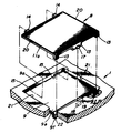
제2도는 본 발명의 한 실시예에 따른 전화기의 본체의 오목한 부분과 덮개를 나타낸 사시도.2 is a perspective view showing a concave portion and a cover of the main body of the telephone according to an embodiment of the present invention.
제3도는 본체에 덮개를 설치한 제2도의 선 Ⅲ-Ⅲ을 절개한 단면도.3 is a cross-sectional view taken along the line III-III of FIG. 2 with a cover attached to the main body.
제4도는 본체에 덮개를 설치한 제2도의 선 Ⅳ-Ⅳ을 절개한 단면도.4 is a cross-sectional view taken along the line IV-IV of FIG. 2 with a cover attached to the body.
제5도는 본체에 덮개를 설치한 제2도의 선 Ⅴ-Ⅴ을 절개한 단면도.5 is a cross-sectional view taken along the line V-V of FIG. 2 with a cover attached to the main body.
제6도는 본 발명의 다른 실시예 따른 덮개와 오목한 부분의 요부를 나타낸 개략도.Figure 6 is a schematic diagram showing the main portion of the cover and the recessed portion according to another embodiment of the present invention.
제7도는 덮개를 설치한 제6도의 오목한 부분의 평면도.FIG. 7 is a plan view of the concave portion of FIG. 6 with a cover. FIG.
제8도는 제7도의 선 Ⅷ-Ⅷ을 절개한 단면도.8 is a cross-sectional view taken along the line VII-VII of FIG.
* 도면의 주요부분에 대한 부호의 설명* Explanation of symbols for main parts of the drawings
1 : 본체 2 : 다이알 키이1: body 2: dial tall
3 : 기능 키이 4 : 퀵-다이알 키이(Quick-dial key)3: Function key 4: Quick-dial key
5 : 메모리 키이 6, 7 : 이름판5: memory key 6, 7: name plate
8 : 덮개 11 : 천장8: cover 11: ceiling
12, 13 : 측벽 14, 16 : 돌출부12, 13:
17 : 돌기17: turning
본 발명은 덮개가 있는 케이스, 특히 전화기 케이스에 사용되는 덮개를 부착하는 구조에 관한 것이다.The present invention relates to a structure for attaching a cover for a cover case, in particular a phone case.
현대의 전화기는 여러 가지 기능을 갖도록 개발되어 왔다. 그 결과 이와같은 전화기 본체의 패널(panel)에는 다이알 키이 및 기능 키 이외에도 퀵-다이알 키이와 메모리 키이 및 전화를 걸게될 대상자의 이름, 가령 퀵-다이알 키이에 등록된 이름을 적기 위한 이름판이 부착되어 있다.Modern telephones have been developed with many functions. As a result, the panel of such a telephone body is equipped with a dial key and a function key, in addition to a quick dial key and a memory key, and a name plate for writing the name of the person to be called, for example, the name of the quick dial key. have.
더욱이 이름판이 부착된 본체의 윗부분에는 투명한 덮개를 부착하게 된다.Furthermore, a transparent cover is attached to the upper part of the body to which the name plate is attached.
전화를 걸게 될 대상자의 이름이 전화하는 사람에 따라 다르므로 이름판에 상대방의 이름을 각자 기재할 필요가 있게 된다.The name of the person you are calling will depend on the person you are calling, so you need to list each person's name on the nameplate.
결과적으로 이러한 덮개는 쉽게 부착 및 분리 할 수 있도록 본체에 부착되어야 한다.As a result, these covers should be attached to the body for easy attachment and removal.
종래의 본체에는 이러한 투명덮개를 땔 수 있도록 부착하기 위하여 덮개를 부착하게 될 함몰부가 성형되어 있고, 이 반대편 벽에 각각의 한쌍의 홀이 성형되어 있는 한편 덮개의 반대편 단부의 각각에는 본체의 함몰부의 한쌍의 홀(hole)에 해당하는 한쌍의 돌출부가 설치되어 있다.The conventional body is formed with a recess to which the cover is attached to attach the transparent cover so that a pair of holes are formed in the opposite wall, while each of the opposite ends of the cover is formed with a recess of the main body. A pair of protrusions corresponding to a pair of holes is provided.
본체에 덮개를 부착하는 것은 덮개의 반대편 끝 하나의 돌출부를 본체의 오목한 부분의 측벽의 해당하는 홀에 끼워넣고 나서 덮개가 갖는 탄성을 이용하여 덮개의 반대편 끝의 돌출부를 오목한 부분의 다른 쪽 측벽의 홀에 끼워 넣음으로써 이루어진다.Attaching the cover to the body inserts one protrusion on the opposite end of the cover into the corresponding hole in the side wall of the concave portion of the body, and then uses the elasticity of the cover to take advantage of the protrusion of the opposite end of the cover on the other side wall of the concave portion. By inserting it into the hole.
따라서 부착된 덮개의 반대편은 본체의 오목한 부분의 바닥의 인접면으로 지지되고 반면에 덮개는 본체의 홀에 끼워져 있는 돌출부에 의해 오목한 부분의 바닥으로부터 분리되는 것이 방지된다.The opposite side of the attached lid is thus supported by the adjoining surface of the bottom of the recessed portion of the body, while the lid is prevented from being separated from the bottom of the recessed portion by a protrusion fitted in the hole of the body.
덮개 또는 오목한 부분의 바닥면에 평행한 방향으로 움직이는 것이 방지되는데 그 이유는 끝이 본체의 오목한 부분의 벽에 대하여 인접하여 있기 때문이다.Movement in a direction parallel to the bottom of the cover or recess is prevented because the tip is adjacent to the wall of the recess in the body.
그러나 종래의 덮개를 부착한 이러한 구조는 다음과 같은 문제점을 가지고 있다.However, this structure with a conventional cover has the following problems.
상술한 바와같이 덮개의 반대편 끝중 하나의 돌출부를 오목한 부분의 측벽중 하나의 홀에 끼워넣고 나서 반대편 끝의 나머지 돌출부를 본체의 남은 홀에 끼워 넣음으로써 덮개는 본체에 부착되며 따라서 덮개는 덮개의 탄성에 의해서 본체에 단단하게 부착된다.As described above, the cover is attached to the main body by inserting one projection of one of the opposite ends of the cover into one hole of the side wall of the concave portion, and then inserting the other projection of the opposite end into the remaining hole of the main body, so that the cover is elastic of the cover. It is firmly attached to the main body.
덮개를 본체의 오목한 부분에 단단하게 부착하기 위해서는 본체의 오목한 부분의 반대측벽 사이의 거리(L로 표시)는 덮개의 폭(1로 표시)보다 더 커야하며 상기 덮개의 폭 1과 덮개의 옆 끝에 설치되어있는 돌출부중에서 가장 짧게 돌출되어 있는 높이(m으로 표시)의 합보다 적어야 된다.In order to securely attach the cover to the recessed part of the body, the distance between the opposite walls of the recessed part of the body (indicated by L) must be greater than the width of the cover (indicated by 1) and the width 1 of the cover and the side end of the cover It should be less than the sum of the shortest heights (in m) of the projecting parts.
더욱이 덮개의 탄성이 본체에 덮개를 부착하는데 이용되므로 덮개의 한정된 탄성을 고려하여 결정된 값의 범위내에서 돌출부의 끼워져 있는 길이(l+m-L)(즉 덮개의 폭+가장 짧은 돌출부의 높이-오목한 부분의 반대편 벽사이의 거리)를 설정할 필요가 있다. 그러므로 실제로는 삽입된 길이를 최소화하는 것이 바람직하다.Moreover, since the cover's elasticity is used to attach the cover to the body, the sandwiched length (l + mL) of the protrusion (i.e. the width of the cover + the height-concave portion of the shortest protrusion) within a range of values determined in consideration of the limited elasticity of the cover. You need to set the distance between the walls on the opposite side of. In practice, therefore, it is desirable to minimize the inserted length.
그러나 삽입된 길이가 너무 짧으면 덮개를 본체에 단단하게 부착할 수 없게 되거나 떼었다 붙혔다 함으로써 돌출부가 마모되어 결국에는 덮개가 본체에 단단하게 붙어 있지 못하게 된다.However, if the inserted length is too short, the cover cannot be attached to the main body firmly or detached from the main body so that the protruding portion wears out and eventually the cover cannot be securely attached to the main body.
반대로 삽입된 길이가 너무 길면 덮개 및/또는 본체가 탄성한계를 벗어나 비뚤어져서 못쓰게 된다.On the contrary, if the inserted length is too long, the cover and / or the main body may be skewed out of the elastic limit so that it cannot be used.
특히 덮개의 재료로 투명한 수지가 사용되고 본체에는 다른 재표가 사용되고 이러한 물질들의 선형 팽창계수가 크게 다른 경우에 삽입된 길이는 주변작업온도에 따라 변한다.In particular, when a transparent resin is used as the material of the cover, different materials are used in the body, and the linear expansion coefficients of these materials are significantly different, the inserted length varies according to the ambient working temperature.
주변작업온도가 -20℃에서 60℃의 범위에서 변한다고 가정하면 본체는 폴리스티렌 수지(선형 팽창계수 α=10.2×10⁻⁵/℃)로 만들어지고 덮개는 폴리카르보네이트 수지(선형 팽창계수 β=5.4×10⁻⁵/℃)로 만들어지고 덮개와 오목한 부분의 폭은 100mm(즉, L=1=100mm)이며 삽입된 길이의 최대 변화는 0.4mm이다.Assuming that the ambient working temperature varies in the range of -20 ° C to 60 ° C, the body is made of polystyrene resin (linear expansion coefficient α = 10.2 × 10 -5 / ° C) and the cover is made of polycarbonate resin (linear expansion coefficient β = 5.4 × 10 -5 / ° C), the width of the cover and the recess is 100mm (ie L = 1 = 100mm) with a maximum change of 0.4mm in length.
본 발명의 목적은 덮개를 케이스의 본체에 일정한 방법으로 부착하기 위한 구조를 제공하는 것이며 이에따라 덮개의 돌출부를 본체에 마련된 홀에 끼워넣는 길이는 본체 및 덮개의 크기와 무관하고 또한 덮개의 선형 열팽창계수가 본체의 열팽창계수와 다를 경우에라도 주변작업온도의 변화와는 무관하게 덮개를 본체에 단단하게 부착할 수 있다.SUMMARY OF THE INVENTION An object of the present invention is to provide a structure for attaching a cover to a body of a case in a predetermined manner, and thus the length of fitting the protrusion of the cover into a hole provided in the body is independent of the size of the body and the cover, and also the linear thermal expansion coefficient of the cover. The cover can be firmly attached to the body even if the temperature is different from the coefficient of thermal expansion of the body.
이 목적을 달성하기 위하여서 케이스의 본체의 함몰부에 덮개를 부착하는 구조는 첫째 덮개의 한 끝이 함몰부의 한 측벽으로부터 떨어져 나가는 것을 방지하기 위한 장치와 둘째 한 끝에 대향하고 있는 덮개의 다른 끝이 한측벽에 대향하는 함몰부의 다른 측벽으로부터 떨어져 나가는 것을 방지하기 위한 장치와 함몰부의 다른 측벽 부근에서 덮개가 함몰부의 한측벽방향으로 움직이는 것을 방지하기 위한 장치로 되어 있다.In order to achieve this purpose, the structure of attaching the cover to the depression of the main body of the case has a device for preventing one end of the cover from falling off one side wall of the case and the other end of the cover facing the second end of the cover. A device is provided to prevent falling out of the other side wall of the depression opposite the wall, and a device to prevent the cover from moving in the direction of one wall of the depression near the other side wall of the depression.
따라서 본 발명은 덮개의 양 단부와 케이스 본체의 대응하는 요부와의 사이에 각각의 걸림장치를 성향하여 이들 걸림장치에 의해 상기 덮개가 함몰부의 상부지지면을 따라 단부방향으로 이동하는 것 및 상기 덮개가 함몰부로부터 이격하는 방향으로 이동하는 것을 각각 방지하도록 되어있는 종래의 기술과 비교하여, 덮개의 양단부와 케이스 본체의 대응하는 요부와의 사이에 각각의 걸림장치를 성형함과 동시에 상기 덮개와 케이스 본체의 대응하는 요부와의 사이에 위치 결정장치를 성형하여 상기 덮개가 함몰부로부터 이격하는 방향으로 이동하는 것을 상기 걸림장치로 저지시키고 동시에 상기 덮개가 함몰부의 상부지지면을 따라 단부방향으로 이동하는 것을 상기의 위치 결정장치로 지지시키도록 한 것 즉, 덮개의 이동을 지지하는 기능이 상기의 걸림장치와 위치 결정장치에 분담되어 있는 것에 특징이 있다.Accordingly, the present invention inclines each catching device between both ends of the cover and the corresponding recessed portion of the case body so that the cover moves in an end direction along the upper supporting surface of the recessed portion by the catching device and the cover Compared to the prior art in which the respective movements in the direction away from the recesses are formed, forming the respective catches between the both ends of the lid and the corresponding recesses of the case body, and simultaneously The positioning device is formed between the corresponding recessed portion of the main body to prevent the cover from moving in the direction away from the recessed portion with the catching device and at the same time the cover is moved in the end direction along the upper ground surface of the recessed portion. To support the movement of the lid, i.e. It is characterized in that is shared with the engaging device with the positioning device.
첨부된 도면을 참고로하여 본 발명을 상세히 설명하면 다음과 같다.Hereinafter, the present invention will be described in detail with reference to the accompanying drawings.
제1도에 도시된 전화기의 패널표면에 다이알 키이(2), 기능 키이(3), 퀵-다이알 키이(4), 메모리 키이(5)가 설치되어 있고 이름판(6)이 부착되어 있어 퀵-다이알 키이(4)에 설치된 전화를 걸 대상자의 이름이 기재되고 이름판(7)이 설치되어 여기에는 전화기 소유자의 이름이 기재된다.A
이름판(6), (7)과 메모리 키이(5)가 부착된 패널표면에는 앞으로 설명하게 되는 바와같이 투명한 덮개(8)로 덮혀 있다.The panel surface to which the name plates 6, 7 and the memory key 5 are attached is covered with a
제2도는 본체(1)과 덮개(8)로 덮혀지는 본체(1)의 오목한 부분(9)으로 형성되어 있다.2 is formed by the
함몰부(9)의 내부에는 기저부(10)가 형성되어 있다.The
덮개(8)는 본체(1)의 패널표면과 측벽(12), (13)에 평행하게 배치되어 있는 천장(11)으로 되어 있다.The
본체(1)의 오목한 부분(9)위에 놓여 있는 덮개(8)는 천장(11)의 아래쪽 면(11a)에서 본체(1)의 기저부(10)의 상부 접촉면(10a)에 의하여 지지된다.The
더욱이 덮개(8)에는 측벽(12)에 두 개의 돌출부(14)가 설치되어 있다.Furthermore, the
덮개(8)의 돌출부(14)에 해당하는 홀(15)이 본체(1)의 함몰부(9)의 측벽(9a)에 있고 여기에 돌출부(14)가 끼워져 있다.A
덮개(8)의 돌출부(14)와 본체(1)의 홀(15)에 의해 첫째 걸림장치가 구성된다.The first locking device is constituted by the
측벽(12)에 대향하고 있는 덮개(8)의 다른 측벽(13)은 상부 바깥표면의 중심부에 있는 두 개의 돌출부(16)으로 되어 있다.The
측벽의 바닥면(13a)은 얇게 만들어져 있으며 두 개의 돌출부(16)사이에는 아래쪽에 돌기(17)가 있다. 더욱이 함몰부(9)의 측벽(9b)과 기저부(10)의 측벽(10b) 사이에는 틈이 생겨서 여기에 덮개(8)의 측벽(13)이 끼어질 수 있게 된다.The bottom surface 13a of the side wall is made thin and has a
기저부(10)의 측벽(10b)과 함몰부(9)의 측벽(9b)이 덮개(8)의 측벽(13)으로 위치 결정장치가 구성된다.The positioning device is constituted by the side wall 10b of the
함몰부(9)의 측벽(9b)의 측벽(9b)에는 리세스(18)가(제5도 참조) 한 지점에 설치되어 있어 덮개(8)가 본체(1)에 부착될 때 덮개(8)의 돌기(17)와 맞물리게 된다.The
리세스(18)의 반대편에 있는 기저부(10)의 측벽(10b)의 한 부분에 오목부(19)가 있다. 돌기(17)의 리세스(18)에 의해 둘째 걸림장치가 구성된다.There is a
본체(1)의 외곽측벽에는 손가락으로 덮개를 쉽게 제거할 수 있도록 하기 위하여 돌출부(16)에 해당하는 위치에 리세스가 성형되어 있다.In the outer side wall of the main body 1, a recess is formed at a position corresponding to the
상술한 본체(1)와 덮개(8)의 구성으로 본체(1)에 덮개(8)를 부착하는 것은 첫째 제3도에 나타난 바와같이 덮개(8)의 돌출부(14)를 본체(1)의 홈(15)에 끼워넣고 나서 제4도에 나타난 바와같이 덮개(8)의 측벽(13a)을 기저부(10)의 측벽(10b)과 함몰부(9)의 측벽(9b)사이에 있는 홈에 끼워넣는 한편 제5도에 도시된 바와같이 덮개(8)의 돌기(17)를 리세스(18)에 끼워 넣음으로써 이루어진다.Attaching the
덮개(8)를 본체(1)에 부착할 때 덮개(8)의 천장(11)의 뒷면(11a)은 기저부(10)의 상부 접촉면(10a)에 의해서 지지된다.When attaching the
제3도에서 5도에 대하여 설명하면, 덮개(8)는 리세스(15)의 상부벽(9c)과 리세스(18)의 상부벽(9d)에 의해 윗방향으로 움직이는 것이 방지된다. 더욱이, 덮개(8)는 기저부(10)의 측벽(10b)과 함몰부(9)의 측벽(9b)에 의해 제2도에 있는 화살표 A방향으로 수평으로 움직이는 것이 방지된다.Referring to FIGS. 3 to 5, the
또한 덮개(8)는 본체(1)의 함몰부(9)의 벽(21)에 의해 다른 수평방향으로 움직이는 것이 방지된다(제2도 참조).In addition, the
이 실시에서 덮개(8)의 걸림장치는 기저부(10)의 측벽(10b)과 함몰부(9)의 측벽(9b)사이에 있는 홈에서 이루어지며 덮개(8)의 측벽(13a)은 이 홈에 삽입된다.In this embodiment the locking device of the
그러나 이 장치는 여기에만 국한되지는 않는다.However, this device is not limited to this.
가령 덮개(8)의 천장(11)의 뒷면(11a)에 성형되어 있는 오목부와 본체(1)의 기저부(10)에 부착된 돌출부에 의해서도 이루어질 수 있다.For example, it may be made by a recess formed in the
더욱이 덮개(8)의 한 측면이 측벽(13)의 인접한 곳에 위치하는 어떠한 구조에도 적용가능하다.Moreover, it is applicable to any structure in which one side of the
상기 실시에서 상부 접촉면(10a)로부터 덮개(8)가 분리되는 것을 방지하기 위한 둘째 걸림장치는 덮개(8)의 측벽(13)에 성형된 돌기(17)와 함몰부(9)의 측벽(9b)에 성형된 리세스(18)에 의해 이루어지며 여기에 돌기(17)가 덮개(8)의 측벽(13a)의 탄성을 이용하여 삽입된다.In the above embodiment, the second locking device for preventing the
그러나 둘째 걸림장치는 이러한 구조에만 국한되지 않는다. 이것은 텅세그먼트(tongue segment)의 탄성의 영향을 받아 본체(1)의 한쪽 단부에 돌기가 성형되어 있는 텅세그먼트를 설치하고, 덮개(8)의 측벽(13)과 돌기를 맞물리게 함으로써 이루어질 수 있다. 더욱이 본체(1)에 성형된 걸림장치의 요부와 덮개를 설치함으로서도 가능하다.However, the second locking device is not limited to this structure. This can be done by providing a tongue segment in which a projection is formed at one end of the main body 1 under the influence of the elasticity of the tongue segment, and engaging the projection with the
제6도에서 제8도에 대한 본 발명의 또다른 실시를 설명하면 특히 본 발명의 기능면이 기술되어진다. 제6도에서도 첫째 실시 상태와 같은 각 부재에 대한 인용 번호를 사용하고 있다. 제6도에서 도시된 바와같이 먼저 실시에 이용된 기저부(10)는 설치되어 있지 않다.Another embodiment of the invention with respect to FIGS. 6 to 8 describes in particular the functional aspects of the invention. In Fig. 6, the same reference numerals are used for each member as in the first embodiment. As shown in FIG. 6, the base 10 used for the first implementation is not provided.
대신 홈(22)이 함몰부(9)의 끝에 형성되어 있다. 홈(22)에는 덮개(8)의 측벽(13)을 맞추기 위한 측벽(9f)가 있다.Instead,
덮개(8)는 먼저 덮개(8)의 돌출부(14)를 본체(1)의 리세스(15)에 끼워넣음으로써 본체(1)에 부착되고 그 다음 덮개(8)의 측벽(13)을 홈(22)에 끼워넣는 한편 덮개(8)의 돌기(17)을 본체(1)의 다른 리세스(18)에 끼워넣는다.The
이렇게 본체(1)에 부착된 덮개(8)는 제7도에 도시되어 있다. 따라서 덮개(8)는 제8a도에 나타난 바와 같이 홈(22)(이 홈의 폭은 W이다)과 덮개(8)의 측벽(13)(이 측벽의 두께는 D이다)에 의해 좌우방향으로 위치하게 된다.The
덮개(8)가 윗방향으로 움직이는 것은 덮개(8)의 돌출부(14)와 본체(1)의 리세스(15)의 상부벽(9c) 사이에 있는 걸림장치와 덮개(8)의 돌기(17)(이 못의 돌출된 길이는 d이다)와 본체(1)의 다른 리세스의 상부벽(9d)사이에 있는 걸림장치에 의해 방지된다.The upward movement of the
덮개(8)의 돌기(17)가 본체(1)의 리세스(18)에 삽입된 량은 D+d-W로 나타내어진다.The amount of the
이 실시에서 본체(1)와 덮개(8)가 다른 선형 열팽창계수를 가진 다른 물질로 만들어져 있다고 할지라도 온도변화에 관계없이 본체(1)와 덮개(8) 사이에 걸린 상태를 일정하게 유지할 수 있는데 그 이유는 온도변화에 의해 발생한 본체(1)이 오목한 측벽(9b)과 덮개(8)의 측벽(13) 사이에 틈(G) (=W-D)의 변화가 아주 적기 때문이다.In this embodiment, even if the body 1 and the
따라서 삽입된 길이의 양(D+d-W)은 온도변화에 관계없이 실제로 일정할 수 있다. 못(17)의 높이의 최소크기는 온도변화를 고려할 때 결정되어 진다.Thus, the amount of inserted length (D + d-W) can actually be constant regardless of temperature change. The minimum size of the height of the
이제 본체(1)의 선형 팽창계수를 α라 하고 덮개(8)의 선형 팽창계수를 β(<α)라 하고 주변작업온도 범위를 t0-t1℃라고 하자.Now let the linear expansion coefficient of the body 1 be α, the linear expansion coefficient of the
제8b도는 본체(1)과 덮개(8)가 가장 낮은 주변작업온도하에 있다는 것을 나타낸다고 생각하면 W0=D0로 된다.Considering FIG. 8B shows that the main body 1 and the
제8c도가 본체(1)과 덮개(8)가 가장 높은 주변작업온도하에 있다는 상태를 나타낸다고 생각하면 W1≤D1+d1로 된다.Considering Fig. 8C, the main body 1 and the
그러면 상기 관계를 충족하는 d의 양은 다음과 같다.Then the amount of d that satisfies the above relationship is as follows.
0≤W1-D1=W0(α-β)(t1-t0)≤d (1)0≤W 1 -D 1 = W 0 (α-β) (t 1 -t 0 ) ≤d (1)
d의 값이 식(1)을 충족할 때 덮개(8)이 본체(1)에 안정된 방법으로 단단하게 부착되었음을 나타낸다.When the value of d satisfies equation (1), the
가령 주변작업온범위가 -20℃에서 60℃이면 본체(1)는 폴리스티렌수지(선형 팽창계수 α=10.2×10⁻⁵/℃)로 만들어지고 덮개(8)는 폴리카르보네이트 수지(선형 팽창계수 β=5.4×10⁻⁵/℃)로 만들어지며 홈(22)의 양 폭(W0)와 측벽(13)의 두께(D0)는 1.5mm이어서 식(1)은 다음과 같이 다시 쓸수 있다.For example, if the ambient working temperature range is -20 ° C to 60 ° C, the body 1 is made of polystyrene resin (linear expansion coefficient α = 10.2 × 10 -5 / ° C) and the
0![]()
![]()
![]()
![]()
결과적으로 못(17)의 높이(d)의 필요한 최소량은 아주 적은 약 0.006mm이다.As a result, the minimum required amount of the height d of the
부수적으로 제8b도와 8c도에 나타난 바와 같이 오목부분(15)의 깊이와 오목부분(15)에 삽입된 돌출부(14)의 길이를 확대함으로써 본체(1)와 덮개(8)이 걸리게 되는 것이 온도변화에 영향을 받지 않는다.Incidentally, as shown in FIGS. 8B and 8C, the main body 1 and the
본 발명의 기능은 두 번째 실시를 참고로 기술되어 있다. 그러나 이 기능도 첫째 실시를 참고로하여 이루어질 수 있으며 그 이유는 이 두 실시가 기능적으로 같기 때문이다.The function of the present invention is described with reference to the second embodiment. However, this function can also be achieved with reference to the first implementation, since the two implementations are functionally the same.
본 발명을 설명하기 위하여 한 실시를 예로 설명하였지만 본 발명은 본 발명의 범위내에서 변형 또는 수정하여 실시할 수 있다.One embodiment has been described by way of example to illustrate the invention, but the invention can be practiced with modifications or variations within the scope of the invention.
Claims (7)
Applications Claiming Priority (2)
| Application Number | Priority Date | Filing Date | Title |
|---|---|---|---|
| JP??59-251555 | 1984-11-30 | ||
| JP59251555A JPS61131499A (en) | 1984-11-30 | 1984-11-30 | Cover mouning construction |
Publications (2)
| Publication Number | Publication Date |
|---|---|
| KR860004522A KR860004522A (en) | 1986-06-23 |
| KR900001027B1 true KR900001027B1 (en) | 1990-02-24 |
Family
ID=17224563
Family Applications (1)
| Application Number | Title | Priority Date | Filing Date |
|---|---|---|---|
| KR1019850008953A KR900001027B1 (en) | 1984-11-30 | 1985-11-29 | Telephone cover |
Country Status (4)
| Country | Link |
|---|---|
| US (1) | US4616764A (en) |
| JP (1) | JPS61131499A (en) |
| KR (1) | KR900001027B1 (en) |
| CA (1) | CA1238736A (en) |
Families Citing this family (9)
| Publication number | Priority date | Publication date | Assignee | Title |
|---|---|---|---|---|
| US4733778A (en) * | 1986-09-25 | 1988-03-29 | Illinois Tool Works Inc. | Reuseable carrier tape |
| US5251104A (en) * | 1992-06-25 | 1993-10-05 | Motorola, Inc. | Enclosure latch system including a bearing surface tapering from flat to cylindrical |
| US5610644A (en) * | 1992-12-22 | 1997-03-11 | Hewlett-Packard Company | Thermal ink-jet pen with a plastic/metal attachment for the cover |
| JP2006133249A (en) * | 2004-11-02 | 2006-05-25 | Ricoh Co Ltd | Display body attaching structure, equipment and image forming apparatus equipped with the display body attaching structure |
| DE102004061974B4 (en) * | 2004-12-23 | 2010-04-29 | Adc Gmbh | Sealing for covers of labeling fields |
| DE102004061973A1 (en) * | 2004-12-23 | 2006-07-13 | Adc Gmbh | Cover for label area of housing or front panel of electrical equipment or connection, has cover part and base body with elastically deformable parts so that they are spring-latched together |
| US7422454B1 (en) * | 2007-03-20 | 2008-09-09 | Kingston Technology Corporation | Retractable memory drive |
| US7811101B2 (en) * | 2007-03-20 | 2010-10-12 | Kingston Technology Corporation | Retractable memory drive |
| NL2013952B1 (en) * | 2014-12-10 | 2016-10-11 | Opticon Sensors Europe B V | Handheld scanner. |
Family Cites Families (3)
| Publication number | Priority date | Publication date | Assignee | Title |
|---|---|---|---|---|
| US4431114A (en) * | 1982-09-30 | 1984-02-14 | Arnold Kleinfeld | Container and removable cover |
| US4493433A (en) * | 1984-04-10 | 1985-01-15 | Leonardo Sideri | Self-locking pilfer proof tamper evident container |
| US4541538A (en) * | 1984-04-16 | 1985-09-17 | General Electric Company | Wiring device covers |
-
1984
- 1984-11-30 JP JP59251555A patent/JPS61131499A/en active Granted
-
1985
- 1985-11-29 CA CA000496610A patent/CA1238736A/en not_active Expired
- 1985-11-29 KR KR1019850008953A patent/KR900001027B1/en not_active IP Right Cessation
- 1985-12-02 US US06/803,735 patent/US4616764A/en not_active Expired - Lifetime
Also Published As
| Publication number | Publication date |
|---|---|
| US4616764A (en) | 1986-10-14 |
| JPH0580838B2 (en) | 1993-11-10 |
| KR860004522A (en) | 1986-06-23 |
| CA1238736A (en) | 1988-06-28 |
| JPS61131499A (en) | 1986-06-19 |
Similar Documents
| Publication | Publication Date | Title |
|---|---|---|
| KR900001027B1 (en) | Telephone cover | |
| US4311893A (en) | Push button assembly | |
| KR850008745A (en) | Holder storage case | |
| US2624965A (en) | Telephone indicia card holder | |
| JP2894577B2 (en) | Battery storage device | |
| JPS6238749B2 (en) | ||
| KR910008820A (en) | IC holder | |
| US4544301A (en) | Keyboard assembly | |
| JPH0129717Y2 (en) | ||
| JPS61123599A (en) | Card holder | |
| JPS5927100Y2 (en) | Printed circuit board mounting structure | |
| JPS6031323Y2 (en) | Phone number card mounting structure | |
| JPH0624075Y2 (en) | Cabinet equipment | |
| KR200317233Y1 (en) | Structurc of shield pin of PCB of mobile phone | |
| JPS6033645Y2 (en) | Phone number list mounting structure | |
| KR200153012Y1 (en) | Flap fixing device of video tape cassette | |
| KR800000346Y1 (en) | Container for a magnestic cassette tape | |
| JPS6111862U (en) | Device to prevent shoji from coming off | |
| JPH0425471Y2 (en) | ||
| JPS5828781A (en) | Display element mount construction | |
| KR19990025856U (en) | Charger for Cell Phones | |
| JP2000030002A (en) | Guiding and holding device for smart card | |
| JPH0448596Y2 (en) | ||
| JPH024587Y2 (en) | ||
| JPS61288325A (en) | Metal button mounting apparatus |
Legal Events
| Date | Code | Title | Description |
|---|---|---|---|
| A201 | Request for examination | ||
| E902 | Notification of reason for refusal | ||
| G160 | Decision to publish patent application | ||
| E701 | Decision to grant or registration of patent right | ||
| GRNT | Written decision to grant | ||
| FPAY | Annual fee payment |
Payment date: 20050120 Year of fee payment: 16 |
|
| EXPY | Expiration of term |