KR900000077B1 - Piezo electric device - Google Patents
Piezo electric device Download PDFInfo
- Publication number
- KR900000077B1 KR900000077B1 KR1019860006485A KR860006485A KR900000077B1 KR 900000077 B1 KR900000077 B1 KR 900000077B1 KR 1019860006485 A KR1019860006485 A KR 1019860006485A KR 860006485 A KR860006485 A KR 860006485A KR 900000077 B1 KR900000077 B1 KR 900000077B1
- Authority
- KR
- South Korea
- Prior art keywords
- piezoelectric
- electrode
- terminal
- piezoelectric plate
- plate
- Prior art date
Links
- 230000005540 biological transmission Effects 0.000 claims description 4
- 239000000758 substrate Substances 0.000 abstract 4
- 238000009826 distribution Methods 0.000 description 9
- 239000003990 capacitor Substances 0.000 description 6
- 230000008878 coupling Effects 0.000 description 6
- 238000010168 coupling process Methods 0.000 description 6
- 238000005859 coupling reaction Methods 0.000 description 6
- 238000010586 diagram Methods 0.000 description 6
- 230000004048 modification Effects 0.000 description 4
- 238000012986 modification Methods 0.000 description 4
- 230000001808 coupling effect Effects 0.000 description 3
- 238000000034 method Methods 0.000 description 3
- 238000005094 computer simulation Methods 0.000 description 2
- 230000010355 oscillation Effects 0.000 description 2
- 230000001629 suppression Effects 0.000 description 2
- 241000282320 Panthera leo Species 0.000 description 1
- 238000006243 chemical reaction Methods 0.000 description 1
- 230000000694 effects Effects 0.000 description 1
- 238000001914 filtration Methods 0.000 description 1
- 239000000463 material Substances 0.000 description 1
Images


Classifications
-
- H—ELECTRICITY
- H03—ELECTRONIC CIRCUITRY
- H03H—IMPEDANCE NETWORKS, e.g. RESONANT CIRCUITS; RESONATORS
- H03H9/00—Networks comprising electromechanical or electro-acoustic devices; Electromechanical resonators
- H03H9/02—Details
- H03H9/125—Driving means, e.g. electrodes, coils
- H03H9/13—Driving means, e.g. electrodes, coils for networks consisting of piezoelectric or electrostrictive materials
- H03H9/132—Driving means, e.g. electrodes, coils for networks consisting of piezoelectric or electrostrictive materials characterized by a particular shape
-
- H—ELECTRICITY
- H03—ELECTRONIC CIRCUITRY
- H03H—IMPEDANCE NETWORKS, e.g. RESONANT CIRCUITS; RESONATORS
- H03H9/00—Networks comprising electromechanical or electro-acoustic devices; Electromechanical resonators
- H03H9/46—Filters
- H03H9/54—Filters comprising resonators of piezo-electric or electrostrictive material
- H03H9/542—Filters comprising resonators of piezo-electric or electrostrictive material including passive elements
-
- H—ELECTRICITY
- H03—ELECTRONIC CIRCUITRY
- H03H—IMPEDANCE NETWORKS, e.g. RESONANT CIRCUITS; RESONATORS
- H03H9/00—Networks comprising electromechanical or electro-acoustic devices; Electromechanical resonators
- H03H9/46—Filters
- H03H9/54—Filters comprising resonators of piezo-electric or electrostrictive material
- H03H9/56—Monolithic crystal filters
Landscapes
- Physics & Mathematics (AREA)
- Acoustics & Sound (AREA)
- Chemical & Material Sciences (AREA)
- Crystallography & Structural Chemistry (AREA)
- Piezo-Electric Or Mechanical Vibrators, Or Delay Or Filter Circuits (AREA)
Abstract
Description
제1a, b 및 c도는 선행기술에 따른 3단자 압전필터 소자의 표시도.1a, b and c are schematic views of a three-terminal piezoelectric filter element according to the prior art.
제2도는 제1a-1c도의 3단자 압전필터소자를 사용하는 필터의 회로도.FIG. 2 is a circuit diagram of a filter using the three-terminal piezoelectric filter element of FIGS. 1A-1C.
제3a, b 및 c도는 선행기술에 빠른 2단자 압전공진기 소자의 표시도.3a, b and c are schematic views of a two-terminal piezoelectric resonator element which is fast in the prior art.
제4도는 2단자 압전공진소자를 사용하는 사다리필터의 회로도.4 is a circuit diagram of a ladder filter using a two-terminal piezoelectric resonance element.
제5도는 장방형 압전소자의 임피이던스 특성을 표시하는 그래프.5 is a graph showing impedance characteristics of a rectangular piezoelectric element.
제6a-b도는 우성방식진동과 여러 스퓨리어스(spurious) 방식진동을 위한 장방형 압전소자의 전하분포를 표시하는 도표.6A-B are diagrams showing charge distribution of rectangular piezoelectric elements for dominant vibration and various spurious vibrations.
제7a, b 및 c도는 본 발명의 제1실시에 따른 3단자 압전필터소자의 정부평면도, 바닥평면도 및 단면도.7a, b and c are top, bottom, and cross-sectional views of a three-terminal piezoelectric filter element according to a first embodiment of the present invention.
제8, 9, 10, 11 및 12도는 제7a도의 3단자 압전필터소자의 다른 수정을 표시하는 정부 평면도.8, 9, 10, 11, and 12 are plan views showing different modifications of the three-terminal piezoelectric filter element of FIG. 7A.
제13a, b 및 c도는 아암끝의 다른형을 표시하는 부분표시도.Figures 13a, b and c are partial views showing different shapes of the arm tips.
제14도는 본 발명의 압전필터소자를 사용하는 AM 라디어 수신기용 IF필터의 회로도.14 is a circuit diagram of an IF filter for an AM radio receiver using the piezoelectric filter element of the present invention.
제15도는 제14도에 유사하나 변압기를 더 사용하는 회로도.FIG. 15 is a circuit diagram similar to FIG. 14 but further using a transformer.
제16도는 제15도의 것과 동일하나 선행기술의 압전기필터 소자와 함께 결합커패시터를 사용하는 회로도.FIG. 16 is the same as that of FIG. 15, but uses a coupling capacitor with a piezoelectric filter element of the prior art.
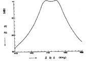
제17도는 제14도의 IF필터의 주파수특성을 표시하는 그래프.17 is a graph showing the frequency characteristics of the IF filter of FIG.
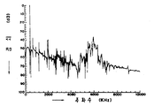
제18도는 제14도의 IF필터의 스퓨리이어스 특성을 표시하는 그래프.FIG. 18 is a graph showing the spurious characteristics of the IF filter of FIG.
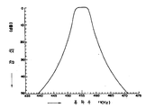
제19도는 제15도의 IF필터의 주파수특성을 표시하는 그래프.19 is a graph showing the frequency characteristics of the IF filter of FIG.
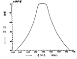
제20도는 제15도의 IF필터의 스퓨리어스 특성을 표시하는 그래프.20 is a graph showing the spurious characteristics of the IF filter of FIG.
제21도는 제16도의 IF필터의 주파수 특성을 표시하는 그래프.21 is a graph showing the frequency characteristics of the IF filter of FIG.
제22도는 제16도의 IF필터의 스퓨리어스 특성을 표시하는 그래프.22 is a graph showing the spurious characteristics of the IF filter of FIG.
제23a, b 및 c도는 본 발명의 제2실시에 따른 2단자 압전공진기소자의 정부평면도, 바닥평면도 및 단면도.23a, b and c are top, bottom and sectional views of a two-terminal piezoelectric resonator device according to a second embodiment of the present invention.
제24도는 제2실시의 수정을 표시하는 정부평면도.FIG. 24 is a government plane diagram showing a modification of the second implementation. FIG.
* 도면의 주요부분에 대한 부호의 설명* Explanation of symbols for main parts of the drawings
1 : 압전판 2 : 링전극1
4 : 접지전극 5 : 필터소자4
13 : 중앙전극 55, 56 : 압진공진기소자13:
62 : 림부분 65 : 제1전극62: rim 65: first electrode
67 : 압진판 69 : 제2전극67: piezoelectric plate 69: second electrode
본 발명의 AM 라이오 수신기용 IF(intermediate frequency 중간주파수) 필터에 사용되는 3단자 압전필터소자 또는 사다리필터 또는 발진기에 사용되는 2단자 압전공진소자와 같은 압전소자에 관한 것이다.A piezoelectric element such as a three-terminal piezoelectric filter element used in an intermediate frequency (IF) filter for an AM lion receiver of the present invention or a two-terminal piezoelectric resonator element used in a ladder filter or an oscillator.
3단자 압전필터소자(5)가 제1a-1c도에 표시되고 그것은 장방형 압전판(1), 링전극(2), 중앙전극(3) 및 접지전극(4)을 포함한다. 링전극(2)과 중앙전극(3)은 압전판의 한면에 퇴적되고 접지전극(4)은 그것의 다른면의 퇴적된다.A three-terminal
3단자 압전필터소자가 AM라이오 수신기의 IF필터에 사용될때, 2개 또는 그 이상의 필터소자(5)가 제2도에 표시된 바와 같은 방법으로 데이터 송신선에 삽입된 결합 커패시터(Co)와 직렬로 접속된다. 제2도에서 데이터 송신신(D)이 중앙전극간에 접속되나, 그것은 링전극간 또는 중앙과 링전극간에 접속될 수 있다. 데이터 송신선에 삽입된 커패시터(Co)는 커플링효과를 감소하기 위하여 제공된다.When a three-terminal piezoelectric filter element is used for the IF filter of an AM radio receiver, two or
IF필터의 크기를 최소로 하는 견지에서, 다른 회로소자를 함유하는 칩소자에 통상적으로 외부적으로 제공되는 결합 커패시터(Co)를 제거하는 것이 양호하다. 그러나, 결합커패시터(Co)가 중앙전그을 직접 연결하게 제거될때 결합효과는 요구된 레벨에 감소되지 않을 것이다. 이 경우에서 결합효과는 중앙전극(3)과 접지전극(4)간의 정전커패시턴스를 감소하는 것에 의하여 감소되고 전기신호와 필터소자의 기계적인 운동간의 변환효과를 감소하는 것에 의하여 역시 감소된다. 그러나, 중앙전극이 크게에서 감소될때 바라지 않은 스퓨리어스 방식 진동이 필터링 주파수의 ×3, ×5, 및 ×7의 주파수범위에서 산출되는 것 같은 다른 문제가 생긴다.In view of minimizing the size of the IF filter, it is preferable to eliminate the coupling capacitor Co, which is normally externally provided to the chip element containing other circuit elements. However, the coupling effect will not be reduced to the required level when the coupling capacitor Co is removed to directly connect the central electric cable. In this case the coupling effect is reduced by reducing the electrostatic capacitance between the
그러므로 선행기술에서 결합커패시터(Co)가 없는 상술된 형의 IF필터는 실제적으로 사용되지 아니하였다.Therefore, in the prior art, the IF filter of the above-described type without the coupling capacitor Co has not been practically used.
2단자 압전공진기소자(55)의 예시가 제3a-3c도에 표시되고, 그것은 장방형 압전판(57), 제1전극(58)및 제2전극(59)을 포함한다. 제1전극(58)과 제2전극(59)은 압전판의 대향하는 면에 퇴적된다. 제1전극(58)의 크기는 정전커패시턴스를 감소하도록 제2전극(59)의 크기보다 작다. 사용에서 적어도 하나의 직렬로 접속된 2단자 압전공진기(55)와 적어도 하나의 병렬로 접속된 2단자 압전공진기(56)가 제4도에 표시된 방법으로 입력단자(51) 및 (52)와 출력단자(53) 및 (54)간에 사다리필터를 이루게 접속된다. 그러나, 제1전극이 크기에서 감소될때 바라지 않은 스퓨리어스방식의 진동이 공진주파수의 ×1.5, ×3, ×5 및 ×7의 주파수범위에서 산출되는 상술된 바와 같은 문제가 일어난다.An example of a two-terminal
본 발명은 상술된 결점을 실질적으로 해결하는 견지에서 발달되었고 그의 전형적인 목적은 작은 정전커패시턴스를 가지고 스퓨리어스 방식 진동을 적게하는 3단자 압전필터소자 또는 2단자 압전공진기소자와 같은 개량된 압전소자를 제공하는 것이다.The present invention has been developed in view of substantially solving the above-mentioned drawbacks and its typical object is to provide an improved piezoelectric element such as a three-terminal piezoelectric filter element or a two-terminal piezoelectric resonator element which has a small electrostatic capacitance and reduces spurious vibration. will be.
본 발명의 더하는 목적은 용이하게 제작될 수 있는 상술된 형의 개량된 압전소자를 제공하는 것이다. 이들 및 다른 목적의 달성에서, 본 발명의 한 양호한 실시에 따른 3단자 압전필터소자가 제1 및 제2면을 가진 4변형 압전판, 압전판의 주위의 제1면에 퇴적된 링전극, 링전극내의 한부위의 제1면에 퇴적된 중앙전극 및 압전판의 제2면에 퇴적된 접지전극을 가진다. 중앙전극은 압전판의 적어도 하나의 대각선에 따라 연장하는 적어도 하나의 아암을 가진다.It is a further object of the present invention to provide an improved piezoelectric element of the type described above which can be easily manufactured. In achieving these and other objects, a three-terminal piezoelectric filter element according to one preferred embodiment of the present invention is a quadrilateral piezoelectric plate having first and second surfaces, a ring electrode deposited on a first surface around the piezoelectric plate, and a ring. It has a center electrode deposited on a first side of one portion within the electrode and a ground electrode deposited on a second side of the piezoelectric plate. The central electrode has at least one arm extending along at least one diagonal of the piezoelectric plate.
본 발명의 다른 실시에 따르면, 2단자 압전공진기소자가 제1 및 제2면을 가진 4변형 압전판, 제1면에 퇴적된 제1전극 및 압전판의 제2면에 퇴적된 제2전극을 가진다. 제1전극은 압전판의 주위에 제공된 링부분과 압전판의 적어도 하나의 아암을 가진 중앙부분에 의하여 이루어진다.According to another embodiment of the present invention, a two-terminal piezoelectric resonator element includes a quadrilateral piezoelectric plate having first and second surfaces, a first electrode deposited on the first surface, and a second electrode deposited on the second surface of the piezoelectric plate. Have The first electrode is formed by a ring portion provided around the piezoelectric plate and a central portion having at least one arm of the piezoelectric plate.
본 발명의 이들 및 다른목적과 양상이 첨부한 도면을 참조로하여 그것의 양호한 실시와 관련하여 취해진 다음의 설명부터 나타날 것이다.These and other objects and aspects of the invention will appear from the following description taken in connection with the preferred practice thereof with reference to the accompanying drawings.
본 발명의 설명에 앞서 스퓨리어스 방식진동이 제5도와 제6a-6l도에 관련하여 설명한다.Prior to the description of the present invention, spurious vibrations will be described with reference to FIGS. 5 and 6A-6L.
스퓨리어스 방식 진동을 조사하기 위하여, 대향하는 평탄면에 완전하게 퇴적된 전극을 가진 4.9×4.9×0.5(mm)의 크기를 가진 압전소자시험 모형의 임피이던스특성이 검출된다. 압전기소자시험모형을 위하여 사용되는 물질은 본 발명에 사용되는 소자의 어느것 또는 제1a 또는 3a도에 표시된 것과 동일한 것이다. 검출된 바와 같은 임피이던스 특성이 제5도에 표시되고 여기에서 피이크 "a"는 진동의 요구된 또는 우세한 방식을 위한 주파수의 임피이던스 변화를 표시하고, 다른 피이크 "a"-"l"은 스퓨리어스 방식진동을 위한 주파수의 임피이던스 변화를 표시한다.In order to investigate the spurious vibration, the impedance characteristics of the piezoelectric element test model having a size of 4.9 x 4.9 x 0.5 (mm) with electrodes completely deposited on opposite flat surfaces are detected. The material used for the piezoelectric element test model is the same as that shown in Fig. 1a or 3a or any of the elements used in the present invention. The impedance characteristics as detected are shown in FIG. 5, where peak VIIa represents the change in impedance of the frequency for the required or dominant manner of vibration, while the other peaks VIIa-VIIl are spurious system vibrations. Indicates the change in impedance of the frequency for.
얻어진 임피이던스 특성은 유한 요소법을 통하여 같은 모형의 컴퓨우터모의에 의하여 얻어진 임피이던스 특성과 비교되고 컴퓨우터모의에 의하여 얻어진 임피이던스 특성이 실제의 시험을 통하여 얻어진 것에 대단히 유사한 것을 발견한다. 컴퓨우터를 더 사용해서 상이한 진동주파수를 위한 전하분포가 얻어진다.The obtained impedance characteristics are compared with the impedance characteristics obtained by the computer simulation of the same model through the finite element method and find that the impedance characteristics obtained by the computer simulation are very similar to those obtained through the actual test. Using a computer further, charge distributions for different vibration frequencies are obtained.
제6a도에 진동의 우세한 방식의 전하분포가 표시된다. 점선에 의하여 표시된 장방형은 압전소자의 모양을 표시하고 실선에 의하여 둘러쌓여진 부위는 한순간에 관찰된(-)전하와 같은 전하의 분포를 표시한다. 다음 순간에서 즉 반사이클후에 실선에 의하여 둘러쌓여진 부위는 (+)전하로 채워진다.In Fig. 6a, the charge distribution of the dominant mode of vibration is shown. The rectangle indicated by the dotted line indicates the shape of the piezoelectric element, and the area enclosed by the solid line indicates the distribution of electric charge such as the (-) charge observed at one moment. At the next moment, ie after half a cycle, the area enclosed by the solid line is filled with a positive charge.
제6b도는 제5도에 표시된 피이크 "b"에 대응하는 진동의 제1스퓨리어스 방식의 전하분포를 표시한다. 유사하게 제 6c-6l도는 제5도에 표시된 피이크 "c"-""에 대응하는 진동의 스퓨리어스 방식의 전하분포를 표시한다. 제5도에 표시된 바와같이 피이크 "c", "g", "h" 및 "i" 에 산출되는 스퓨리어스 방식진동은 대단히 작은 진폭을 가진 대단히 약한 것이므로 그들은 무시될 수 있다. 본 발명에 따른 압전기 소자는 아래에 설명되는 방식으로 스퓨리어스 방식진동 특히 제6b, 6e, 6f, 6j, 6k 및 6l도에 각기 표시된 전하분포를 가진 피이크 "b", "e", "f", "j", k" 및 "l"에서 산출되는 스퓨리어스 방식진동을 억압 또는 제거하게 배치된다.FIG. 6B shows the charge distribution of the first spurious method of vibration corresponding to the peak "b" indicated in FIG. Similarly, FIGS. 6C-6L show a spurious charge distribution of vibrations corresponding to the peaks "c"-"" shown in FIG. As shown in FIG. 5, the spurious vibrations produced at peaks "c", "g", "h" and "i" are very weak with very small amplitudes and they can be ignored. The piezoelectric element according to the present invention has a spurious oscillation in the manner described below, in particular peaks "b", "e", "f", with charge distributions indicated in degrees 6b, 6e, 6f, 6j, 6k and 6l, respectively. It is arranged to suppress or eliminate the spurious vibrations calculated in "j", k "and" l ".
제7a, 7b 및 7c도를 참조하면, 본 발명의 제1실시에 따른 3단자 압전필터소자(11)가 표시된다. 3단자 압전필터소자(11)는 대향하는 평탄면을 가진 장방형과 같은 4변형의 압전판(1)을 가진다. 접지전극(4)이 판(1)의 평탄면의 하나에 전체적으로 퇴적되고, 링전극(2)과 중앙전극(13)이 다른 평탄면에 퇴적된다. 링전극(2)이 상기 다른 평탄면의 링에 제공되고, 중앙전극(13)이 링전극(2)에 의하여 둘러쌓여진 부위내에 제공된다. 제1실시에 따르면 링전극(2)은 X의 모양으로 대각선(d1) 및 (d2)에 따라 압전판의 중앙부터 연장하는 4개의 아암(a1), (a2), (a3) 및 (a4)의 폭의변화에 의하여 쉽게 변하게 된다. 스퓨리어스 방식진동은 아래에 설명되는 방법에 의하여 억제된다.7A, 7B and 7C, a three-terminal piezoelectric filter element 11 according to the first embodiment of the present invention is shown. The three-terminal piezoelectric filter element 11 has a four-sided
피이크 "d"의 스퓨리어스 방식진동은 제6d도에 표시된 전하분포를 가지고 여기에서 (+)전하는 중앙에 놓여지고 (-)전하는 4개의 모퉁이에 놓여진다. 중앙전극(13)이 인가될때, 아암(a1-a4)은 (-)및 (+)전하 영역에 브리지되고 그것에 의하여 제6 d도에 표시된 분포를 무효로하게 이들 영역에 축적된 전하를 평형시킨다. 따라서 스퓨리어스 방식진동은 제거되거나 억압된다. 유사한 방법으로 내각선으로 연장된 아암에 의하여 제6e, 6f, 6j, 6k 및 6l도에 표시된 전하분포는 스퓨리어스 방식진동을 억압하게 무효로 된다.The spurious oscillation of the peak "d 를 has the charge distribution shown in Figure 6d, where the positive charge is centered and the negative charge lies at four corners. When the
역시 2아암구조가 사용되어야 할때 4개 아암중의 어느 2개가 직선 또는 V의 형으로 배치되도록 제공된다. 예로서 제10도에서 아암(a2) 및 (a4)가 제공되나 대신에 아암(a1) 및 (a3)가 제공되어도 좋다. 대신으로 아암(a1) 및 (a2) 또는 아암 (a2) 및 (a3)가 제공되어도 좋다.Again, when two arm structures are to be used, any two of the four arms are provided to be arranged in a straight or V shape. By way of example the arms a2 and a4 are provided in FIG. 10 but instead the arms a1 and a3 may be provided. Instead, arms a1 and a2 or arms a2 and a3 may be provided.
더우기 본 발명에 따르면 송곳과 같이 표시된 각 아암의 끝은 제13a도에 표시된 바와 같이 둥근형이라도 좋고, 또는 제13도에 표시된 바와 같이 2개이 직각 모퉁이를 제공하게 형성하는 절단모서리로 제공되어도 좋다.Furthermore, according to the present invention, the end of each arm indicated as an awl may be round as shown in FIG. 13A, or may be provided as a cutting edge which forms two to provide a right corner as shown in FIG.
이들 모퉁이는 제13c도와 같이 둥글게 되어도 좋다. 더우기 표시되어 있지 않지만 결각 또는 돌출이 각 아암에 형성되어도 좋다.These corners may be rounded as in FIG. 13C. Furthermore, although not shown, a cutout or protrusion may be formed on each arm.
역시 아암은 아암이 일반적으로 대각선 방향에 따라 연장하는한 만곡되어도 좋다.Again, the arm may be curved as long as the arm generally extends in the diagonal direction.
제7a-7c도의 2개의 압전필터소자가 주파수특성, 스퓨리어스 특성 및 여러필터데이터를 얻도록 제14도에 표시된 방법으로 AM라디오 수신용 IF필터에 접속된다. 시험작동에서 주파수 445-465KHz 및 0-10KHz를 가진신호가 표준신호 발생기(21)부터 제1단계압전필터소자(11a)에 입력되고 제2단계 압전필터소자(11b)부터 출력된 신호가 고주파전압계(22)에 의하여 검출된다. 제14도의 회로에서 회로소자는 다음의 명세를 가진다.The two piezoelectric filter elements of FIGS. 7A-7C are connected to the AM radio receiving IF filter in the manner shown in FIG. 14 to obtain frequency characteristics, spurious characteristics and various filter data. In the test operation, signals having frequencies of 445-465 KHz and 0-10 KHz are inputted from the
Rg+R1=R2=3000ΩR g + R 1 = R 2 = 3000Ω
C1=50pFC 1 = 50 pF
검출된 결과에서 제17도가 주파수특성을 표시하고, 제18도가 스퓨리어스 특성을 표시하고, 여러 필터데이터는 아래의 표 1에 표시된다.In the detected result, FIG. 17 shows frequency characteristics, FIG. 18 shows spurious characteristics, and various filter data are shown in Table 1 below.
[표 1]TABLE 1

제15도를 참조하면 다른 IF필터가 표시되고, 그것은 더우기 제1단계 압전필터소자(11a)의 입력측에 접속된 변압기(T1)를 가진다. 제15도의 회로에서 회로 소자는 다음의 명세를 가진다.Referring to Fig. 15, another IF filter is displayed, which further has a transformer T1 connected to the input side of the first stage piezoelectric filter element 11a. In the circuit of Fig. 15, the circuit element has the following specification.
R11=300Ω R12=2KΩR11 = 300Ω R12 = 2KΩ
C10=7pF C11=50pFC10 = 7pF C11 = 50pF
같은 시험작동이 제15도의 회로를 위하여 수행되었고, 검출된 결과에서 제19도가 주파수 특성을 표시하고 제20도가 스퓨리어스 특성을 표시하고 여러 필터데이터는 아래의 표 2에 표시된다.The same test operation was performed for the circuit of FIG. 15, and in the detected result, FIG. 19 shows frequency characteristics, FIG. 20 shows spurious characteristics, and various filter data are shown in Table 2 below.
[표 2]TABLE 2

제16도를 참조하면 제15도에 유사한 회로가 비교의 목적을 위하여 표시된다. 압전필터소자(11a)및 (11b) 대신에 제1a - 1c도에 표시된 바와 같은 압전필터소자(5a) 및 (5b)가 결합 커패시터(Co)와 함께 제공된다.Referring to FIG. 16, a circuit similar to FIG. 15 is shown for comparison purposes. Instead of the piezoelectric filter elements 11a and 11b,
같은 시험작동이 제16도의 회로를 위하여 수행되고 검출된 결과에서 제21도가 주파수특성을 표시하고 제22도가 스퓨리어스 특성을 표시하고 여러 필터데이터는 아래의 표 3에 표시된다.The same test operation is performed for the circuit of FIG. 16, and in the detected results, FIG. 21 shows frequency characteristics, FIG. 22 shows spurious characteristics, and various filter data are shown in Table 3 below.
[표 3]TABLE 3

상기 시험결과에 의하여 본 발명에 따른 압전필터소자를 사용하는 IF필터(제15도)는 선행기술의 압전필터소자에 사용하는 IF필터(제16도)에 유사한 작동특성을 가진다. 사실에서, 본 발명에 따른 IF필터(제15도)는 선행기술의 IF필터(제16도)보다 좋은 스퓨리어스 방식 억압을 표시하였다.According to the test results, the IF filter (FIG. 15) using the piezoelectric filter element according to the present invention has a similar operation characteristic to that of the IF filter (FIG. 16) used in the piezoelectric filter element of the prior art. In fact, the IF filter (FIG. 15) according to the present invention exhibited better spurious suppression than the IF filter (FIG. 16) of the prior art.
예로서 표 2 및 3가 비교될때 본 발명에 따른 IF필터(제15도)는 선행기술의 IF필터(제16도)보다 주파수범위 0-3MHz에서 약 8dB 더하는 스퓨리어스 방식진동을 억합하는것이 이해된다.By way of example, when Tables 2 and 3 are compared, it is understood that the IF filter (FIG. 15) according to the present invention suppresses spurious vibrations which add about 8 dB in the frequency range 0-3 MHz than the IF filter (FIG. 16) of the prior art. .
역시 중앙주파수(fo)상의 주파수영역의 감쇠의 피이크는 본 발명에 따른 IF필터(제15도)에 대하여 약 58dB인데 반하여, 동일한 것이 선행기술의 IF필터에 대하여 약 48dB이다.The peak of the attenuation in the frequency domain on the center frequency fo is also about 58 dB for the IF filter (FIG. 15) according to the invention, while the same is about 48 dB for the IF filter of the prior art.
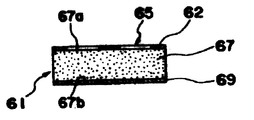
따라서, 본 발명에 따른 IF필터(제15도)는 선행기술의 IF필터(제16도)보다 주파수범위 5.5-7KHz에서 약 10dB 더하는 두께의 스퓨리어스 방식진동을 억제한다고 말할 수 있다. 압전필터소자(5a) 및 (5b)와 압전필터소자(11a) 및 (11b)는 상이한 두께를 가진다는 것이 주의되어야 한다. 두께 스퓨리어스 방식진동의 억압은 두께방식진동에 의하여 야기되는 표면 전하는 압전소자의 중앙에서 강하게 공헌되어 작은 크기의 중앙전극은 구동효율의 감소를 초래한다는 것이 이해되게 된다. 제23a, 23b 및 23c도를 참조하면 본 발명의 제2실시에 따른 2단자 압전공진기소자(61)가 표시된다. 2단자 공진기소자(61)는 대향하는 평탄면(67a) 및 (67b)을 가진 장방형과 같은 4변형의 압전판(67)을 가진다. 제1전극(65)이 한 평탄면(67a)에 퇴적되고 제2전극(69)이 다른 평탄면(67b)에 퇴적된다.Therefore, it can be said that the IF filter (FIG. 15) according to the present invention suppresses the spurious vibration of thickness of about 10 dB more in the frequency range 5.5-7 KHz than the IF filter (FIG. 16) of the prior art. It should be noted that the
제1전극(65)은 링부분내에 십자를 이루도록 4개의 모퉁이부터 대각선(d1) 및 (d2)에 따라 연장하는 4개의 아암(a1), (a2), (a3) 및 (a4)과 평탄면(67a)의 주의 부분에 따라 장방형으로 연장하는 링부분(62)에 의하여 이루어진다.The
제2전극(69)이 평탄면(67b)에 전체적으로 퇴적된다. 제1전극(65)가 제23a에 표시된 방법으로 배치될때 제1전극(65)은 제1a도에 표시된 것과 비교할때 감소되고 따라서 정전기커패시턴스는 감소한다. 정전기 커패시턴스는 각 아암(a1), (a2), (a3) 및 (a4)의 폭의 변화에 의하여 쉽게 변경될 수 있다. 아암(a1), (a2), (a3) 및 (a4)에 의하여 스퓨리어스 방식 진동은 상술된 바와 같은 방법으로 억압된다. 제2실시에 따른 2단자 압전공진기소자는 여러방법으로 변하게 된다. 예로서, 아암(a1-a4)의 수는 아암이 일반으로 대각선(d1) 및/ 또는 (d2)에 따라 연장하는한 제24도에 표시된 바와 같이 2개의 아암(d2) 및 (d4)과 같이 4개보다 적어도 좋다. 역시 압전공진기소자는 제1실시의 수정에서와 같이 평행4변형으로 배치될 수 있다.The
본 발명의 압전공진기소자는 사다리필터에서 사용될때 직렬로 접속된 2단자 압전공진기 소자의 적어도 하나는 제23a-23c도에 표시된 본 발명의 2단자 압전공진기 소자라야 하고, 다른 직렬로 접속된 2단 압전공진기소자는 제3a-3c도에 표시된 바와 같은 선행기술에 따른것으로 될 수 있다.When the piezoelectric resonator element of the present invention is used in a ladder filter, at least one of the two-terminal piezoelectric resonator elements connected in series must be the two-terminal piezoelectric resonator element of the present invention shown in Figs. 23A-23C, and the two stages connected in series. The piezoelectric resonator element may be according to the prior art as shown in FIGS. 3A-3C.
병렬로 접속되는 2단자 압전공진기 소자는 선행기술에 따른 것이라야 한다.Two-terminal piezoelectric resonator elements connected in parallel should be according to the prior art.
사다리필터가 상술된 방법으로 배치되었을때 스퓨리어스 방식진동은 억압되고 동시에 사다리필터는 아래에 설명되는 바와 같이 콜팩트한 크기로 배치될 수 있다.When the ladder filter is arranged in the manner described above, the spurious vibration is suppressed and at the same time the ladder filter can be arranged in a compact size as described below.
사다리필터(제4도)의 크기의 감소의 견지에서 다수의 압전공진기소자는 감소되어야 하고, 그와 동시에 각 공진기 소자의 크기가 감소되어야 하나 요구되는 필터특성은 상실되어서는 안된다.In view of the reduction in the size of the ladder filter (FIG. 4), the number of piezoelectric resonator elements should be reduced, and at the same time the size of each resonator element should be reduced, but the required filter characteristics should not be lost.
이 목적을 위하여 병렬로 접속된 공진기(56)에 직렬로 접속된 공진기의 정전기 커패시턴스 비율을 증가하는 것이 필요하다. 이것은 필터특성의 형상인 수의 퇴화에 기인하나 큰 기인하나 기계적인 품질계수 Qm를 가진 공진기(55) 및 (56)를 사용하는 것에 의하여 개량된다. 공진기(55) 및 (56)의 정전기 커패시턴스 비율을 증가하기 위하여 압전소자(55)의 유진율은 감소되어야하고, 그와 동시에 압전소자(55)의 두께는 두껍게 만들어져야 하다. 더우기 압전소자(56)의 유전율은 증가되어야하고 그와 동시에 소자(56)의 두께는 얇게 만들어져야 한다. 그러나 압전소자(55)가 두껍게 만들어지면 사다리필터의 크기는 요구된 크기로 감소되지 아니하여도 좋다. 역시, 압전소자(56)가 얇게 만들어지면, 압전소자는 쉽게 파손된다. 그러나, 본 발명의 공진기 소자의 사용에 의하여 정전기 커패시턴스는 공진기소자의 두께 또는 요구된 필터특성의 변경없이 아암(a1-a4)의 폭의 변화에 의하여 쉽게 제어될 수 있다.For this purpose, it is necessary to increase the electrostatic capacitance ratio of the resonators connected in series to the
본 발명은 몇개의 양호한 실시를 참조로하여 완전히 설명되었지만 그것의 많은 수정과 변경이 이 분야에 훈련된 사람들에 나타날 것이며, 그러므로 본 발명의 범위는 상술된 양호한 실시의 상세에 의하여 한정되지 않으나 첨부된 크레임의 항목에 의하여만 한정될 것이다.While the present invention has been fully described with reference to some preferred embodiments, many modifications and variations thereof will appear to those trained in the art, and therefore the scope of the invention is not limited by the details of the preferred embodiments described above, but the It will be limited only by the item of the claim.
Claims (17)
Applications Claiming Priority (3)
| Application Number | Priority Date | Filing Date | Title |
|---|---|---|---|
| JP174682 | 1985-08-07 | ||
| JP85-174682 | 1985-08-07 | ||
| JP60174682A JPH0777335B2 (en) | 1985-08-07 | 1985-08-07 | Intermediate frequency filter |
Publications (2)
| Publication Number | Publication Date |
|---|---|
| KR870002670A KR870002670A (en) | 1987-04-06 |
| KR900000077B1 true KR900000077B1 (en) | 1990-01-19 |
Family
ID=15982848
Family Applications (1)
| Application Number | Title | Priority Date | Filing Date |
|---|---|---|---|
| KR1019860006485A KR900000077B1 (en) | 1985-08-07 | 1986-08-06 | Piezo electric device |
Country Status (2)
| Country | Link |
|---|---|
| JP (1) | JPH0777335B2 (en) |
| KR (1) | KR900000077B1 (en) |
Family Cites Families (2)
| Publication number | Priority date | Publication date | Assignee | Title |
|---|---|---|---|---|
| JPS5127736U (en) * | 1974-08-21 | 1976-02-28 | ||
| JPS5653815U (en) * | 1979-10-03 | 1981-05-12 |
-
1985
- 1985-08-07 JP JP60174682A patent/JPH0777335B2/en not_active Expired - Lifetime
-
1986
- 1986-08-06 KR KR1019860006485A patent/KR900000077B1/en not_active IP Right Cessation
Also Published As
| Publication number | Publication date |
|---|---|
| JPH0777335B2 (en) | 1995-08-16 |
| JPS6234411A (en) | 1987-02-14 |
| KR870002670A (en) | 1987-04-06 |
Similar Documents
| Publication | Publication Date | Title |
|---|---|---|
| US3585537A (en) | Electric wave filters | |
| US5294898A (en) | Wide bandwidth bandpass filter comprising parallel connected piezoelectric resonators | |
| US5770985A (en) | Surface acoustic wave filter | |
| KR100859086B1 (en) | A bulk acoustic wave device | |
| US4734664A (en) | Surface acoustic wave resonator | |
| US10476481B2 (en) | Acoustic filtering circuitry including capacitor | |
| US2373431A (en) | Electric wave filter | |
| US4760358A (en) | Piezoelectric element | |
| US5223762A (en) | Surface acoustic wave filter | |
| US4066985A (en) | Television IF filter constructed in accordance with the surface wave principle | |
| US4954793A (en) | Filter bank | |
| US5574414A (en) | High-frequency ladder type piezoelectric filter and piezoelectric resonator therefor | |
| EP0829957B1 (en) | Piezoelectric resonator and electronic component using the same | |
| EP0818881B1 (en) | Piezoelectric resonator and electronic component using the same | |
| US4503350A (en) | Piezoelectric resonator device with a laminated structure | |
| EP0820144B1 (en) | Piezoelectric resonator and electric component using the same | |
| KR900000077B1 (en) | Piezo electric device | |
| US4348609A (en) | Piezoelectric vibrator with spurious mode suppression | |
| EP0802629A2 (en) | Electronic component and ladder filter | |
| US3465178A (en) | Driven-boundary piezoelectric crystals | |
| US5939957A (en) | 6-elements ladder type piezoelectric filter | |
| US3936764A (en) | Frequency discriminator utilizing surface wave devices | |
| JP3146695B2 (en) | Ceramic filter using thickness-shear vibration mode | |
| US3974405A (en) | Piezoelectric resonators | |
| JPH04287402A (en) | Dielectric filter |
Legal Events
| Date | Code | Title | Description |
|---|---|---|---|
| A201 | Request for examination | ||
| G160 | Decision to publish patent application | ||
| E701 | Decision to grant or registration of patent right | ||
| GRNT | Written decision to grant | ||
| FPAY | Annual fee payment |
Payment date: 20060110 Year of fee payment: 17 |
|
| EXPY | Expiration of term |