KR900000008B1 - Floating type magnetic head - Google Patents
Floating type magnetic head Download PDFInfo
- Publication number
- KR900000008B1 KR900000008B1 KR1019840005942A KR840005942A KR900000008B1 KR 900000008 B1 KR900000008 B1 KR 900000008B1 KR 1019840005942 A KR1019840005942 A KR 1019840005942A KR 840005942 A KR840005942 A KR 840005942A KR 900000008 B1 KR900000008 B1 KR 900000008B1
- Authority
- KR
- South Korea
- Prior art keywords
- slider
- floating
- groove
- magnetic head
- core
- Prior art date
Links
Images

Classifications
-
- G—PHYSICS
- G11—INFORMATION STORAGE
- G11B—INFORMATION STORAGE BASED ON RELATIVE MOVEMENT BETWEEN RECORD CARRIER AND TRANSDUCER
- G11B5/00—Recording by magnetisation or demagnetisation of a record carrier; Reproducing by magnetic means; Record carriers therefor
- G11B5/48—Disposition or mounting of heads or head supports relative to record carriers ; arrangements of heads, e.g. for scanning the record carrier to increase the relative speed
- G11B5/58—Disposition or mounting of heads or head supports relative to record carriers ; arrangements of heads, e.g. for scanning the record carrier to increase the relative speed with provision for moving the head for the purpose of maintaining alignment of the head relative to the record carrier during transducing operation, e.g. to compensate for surface irregularities of the latter or for track following
- G11B5/60—Fluid-dynamic spacing of heads from record-carriers
- G11B5/6005—Specially adapted for spacing from a rotating disc using a fluid cushion
-
- G—PHYSICS
- G11—INFORMATION STORAGE
- G11B—INFORMATION STORAGE BASED ON RELATIVE MOVEMENT BETWEEN RECORD CARRIER AND TRANSDUCER
- G11B5/00—Recording by magnetisation or demagnetisation of a record carrier; Reproducing by magnetic means; Record carriers therefor
- G11B5/10—Structure or manufacture of housings or shields for heads
- G11B5/105—Mounting of head within housing or assembling of head and housing
Abstract
Description
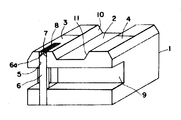
제1도는 종래예의 부동 자기헤드의 사시도.1 is a perspective view of a floating magnetic head of a conventional example.
제2도는 제1도의 주요부의 확대도.2 is an enlarged view of a main part of FIG.
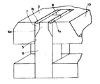
제3도는 본 발명의 한 실시예에 관한 부동자기헤드의 사시도이다.3 is a perspective view of a floating magnetic head according to an embodiment of the present invention.
*도면의 주요부분에 대한 부호의 설명* Explanation of symbols for main parts of drawing
1 : 슬라이더 2 : 슬라이더홈1: Slider 2: Slider groove
3, 4 : 부동면(浮動面) 5 : 코어삽입홈3, 4: floating surface 5: core insertion groove
6 : 자기코어 7 : 유리부재6: magnetic core 7: glass member
8 : 갭8: gap
본 발명은 부동 자기헤드에 관한 것으로서, 특히 부동면에 노출된 유리부재의 면적을 되도록 좁게한 부동 자기헤드에 관한 것이다.The present invention relates to a floating magnetic head, and more particularly to a floating magnetic head in which the area of the glass member exposed to the floating surface is as narrow as possible.
일반적으로 부동자기헤드의 구조는 제1도에 나타낸 바와 같이 세라믹 등의 비자성재에 의해 이루어진 슬리이더(1)에 슬리이더홈(2)를 연삭하여 형성하고 그 슬라이더홈(2)의 양측에 부동면(3), (4)를 설치한다. 2개의 부동면(3), (4)의 한쪽에는 그 중앙에 코어삽입홈(5)이 있고, 이 코어삽입홈(5) 즉, 선단부에 트랙부분(6a)을 설치한 페라이트 등으로 구성된 자기코어(6)를 삽입하고 제2도에 나타낸 바와 같이 유리부재(7)로 접착을 행하였다. 또한 상기 자기코어(6)의 트랙부분(6a)은 그 선단부의 양측을 연삭함으로써 형성된다. 또 9는 자기코어(6)에 감은 코일(도시되지 않음)의 공간을 얻기 위해 슬라이더(1)의 측면에 설치한 홈이다. 여기서 상기 부동면(3), (4)은 랩핑, 폴리싱 가공에 의해 거울면과 같은 폴리싱 가공을 실시하게 되나 그때 부동면(3), (4)에 노출된 슬라이더(1), 유리부재(7), 페라이트자기코어(6) 재료의 상이함에 기인하여 생기는 가공성의 차이에 의해 유리부재 요(凹)부 (7a)가 생긴다.In general, the structure of the floating magnetic head is formed by grinding the
그러나 상기 부동자기헤드를 사용하여 기록매체(도시되지 않음)을 기록재생할 경우에는 이 부동자기헤드를 회전기록 매체면 위에 배치하고, 기록매체를 고속회전시켜 그때의 기록매체의 운동에 따라 생기는 공기흐름에 의하여 부동자기헤드를 기록매체에서 약간 부상시킨 상태로 동작된다.However, in the case of recording and reproducing a recording medium (not shown) using the floating magnetic head, the floating magnetic head is placed on the surface of the rotating recording medium, and the recording medium is rotated at high speed so that the air flow generated by the movement of the recording medium at that time. It is operated with the floating magnetic head slightly floating on the recording medium.
그러나 상기 종래예의 부동 자기헤드에 있어서는 한쪽의 부동면(3)의 유리부재(7)에 요부(7a)가 설치되어 있기 때문에 이 요부(7a)에 의하여 부동면(3)에 부압이 생긴다. 이 부압에 의하여 부동자기헤드의 부상자세가 나빠지고 회전기록 매체와 부동자기헤드와의 사이의 헤드파손 현상에 의해 기록매체를 손상시키기 쉬운 결점이 있었다. 또 자기코어(6)의 갭(8)은 코어삽입홈(5)내에 있고, 주위가 슬라이더(1)로 포위되어 있기 때문에 상기 갭(8)의 깊이 칫수를 확인할 수가 없으며, 깊이 칫수를 관리하는 것이 곤란한 결점이 있었다.However, in the floating magnetic head of the conventional example, since the recessed part 7a is provided in the glass member 7 of the one floating
본 발명은 상기의 결점을 제거하고 부동면에 노출된 유리부분의 면적을 되도록 좁게한 부동자기헤드를 제공하는 것을 목적으로 한다.It is an object of the present invention to provide a floating magnetic head which eliminates the above drawbacks and narrows the area of the glass part exposed to the floating surface as much as possible.
이하 도면에 관하여 그 한 실시예를 설명한다. 제3도에 있어서, 1은 세라믹 등의 비자성재로 이루어진 슬라이더이며, 이 슬라이더(1)에는 슬라이더홈(2)을 연삭으로 형성되고 슬라이더홈(2)의 양측에 부동면(3), (4)이 설치되어 있다. 또 5는 한쪽의 부동면(3)의 슬라이더홈(2)쪽에 설치한 코어삽입홈이며, 이 코어삽입홈(5)은 일부가 슬라이더홈(2)을 침범하고 있다. 또 코어삽입홈(5)에는 트랙부분(6a)이 형성되어 있는 페라이트 등으로서 이루어진 자성코어(6)가 삽입되며, 유리부재(7)에 의해 접착되어 있다. 그리고 상기 자기 코어의 트랙부분(6a)은 그 선단부의 한쪽을 연삭함으로서 형성되고 이 연삭부에 유리부재(7)가 충전된다. 또 슬라이더홈(2)의 양측에 있는 경사면(10) (11)의 모서리 가공은 자기코어(6)를 코어삽입홈(5)에 삽입한 후, 슬라이더홈(2)을 연삭할때 동시에 하든가 또는 슬라이더홈(2)을 연삭한 후에 가공을 행함으로써 부동면(3), (4)에 노출하는 유리부재(7)를 거의 없어지게 할 수 있기 때문에 부동면(3), (4)의 폴리싱가공시에 상기 종래예와 같이 유리부재(7)에 요부(7a)가 생기는 일이 없게된다.One embodiment will now be described with reference to the drawings. In Fig. 3, reference numeral 1 denotes a slider made of a nonmagnetic material such as ceramic, and the slider 1 is formed by grinding the
이상에 기술한 바와 같이 본 발명에 의한 부동자기 헤드에 의하면, 슬라이더에 슬라이더홈을 형성하여 그 슬라이더 홈의 양측에 부동면을 설치하고 코어삽입홈을 슬라이더홈에 인접시킨 것이기 때문에 부동면에 노출하는 유리부재(7)의 면적을 좁게할 수가 있으며, 따라서 랩핑. 폴리싱 가공에서 생기는 유리부재의 요부를 없앨수가 있고, 부동 자기헤드가 부상하였을때에 생기는 부압을 방지할 수 있다. 또 코어삽입홈에 삽입한 자기코어의 갭이 슬라이더홈으로 부터 유리부재를 통해서 볼수가 있으며, 갭의 깊이를 용이하게 관리할 수 있는 현저한 효과를 나타낸다.As described above, according to the floating magnetic head according to the present invention, since the slider groove is formed in the slider, the floating surface is provided on both sides of the slider groove, and the core insertion groove is adjacent to the slider groove. The area of 7 can be narrowed and thus lapping. The recessed portion of the glass member generated in polishing can be eliminated, and the negative pressure generated when the floating magnetic head floats can be prevented. In addition, the gap of the magnetic core inserted into the core insertion groove can be seen from the slider groove through the glass member, and it has a remarkable effect of easily managing the depth of the gap.
Claims (1)
Applications Claiming Priority (3)
| Application Number | Priority Date | Filing Date | Title |
|---|---|---|---|
| JP58240487A JPS60131613A (en) | 1983-12-20 | 1983-12-20 | Floating magnetic head |
| JP58-240487 | 1983-12-20 | ||
| JP240487 | 1983-12-20 |
Publications (2)
| Publication Number | Publication Date |
|---|---|
| KR850005669A KR850005669A (en) | 1985-08-28 |
| KR900000008B1 true KR900000008B1 (en) | 1990-01-18 |
Family
ID=17060240
Family Applications (1)
| Application Number | Title | Priority Date | Filing Date |
|---|---|---|---|
| KR1019840005942A KR900000008B1 (en) | 1983-12-20 | 1984-09-27 | Floating type magnetic head |
Country Status (3)
| Country | Link |
|---|---|
| US (1) | US4658314A (en) |
| JP (1) | JPS60131613A (en) |
| KR (1) | KR900000008B1 (en) |
Families Citing this family (10)
| Publication number | Priority date | Publication date | Assignee | Title |
|---|---|---|---|---|
| DE3630841A1 (en) * | 1985-09-13 | 1987-03-26 | Hitachi Metals Ltd | FLYING MAGNETIC HEAD |
| JPS62192016A (en) * | 1986-02-19 | 1987-08-22 | Alps Electric Co Ltd | Magnetic head for vertical magnetic recording and its production |
| US4870520A (en) * | 1986-05-29 | 1989-09-26 | Magnetic Peripherals Inc. | Read/write head with side winding slot |
| US4870523A (en) * | 1986-07-10 | 1989-09-26 | Hitachi Maxell, Ltd. | Magnetic head apparatus used for movable magnetic medium with head gap positioning |
| US5245488A (en) * | 1986-08-13 | 1993-09-14 | Seiko Epson Corporation | Low-noise composite magnetic head for recording and producing |
| JPH0778853B2 (en) * | 1988-05-06 | 1995-08-23 | 三洋電機株式会社 | Floating type magnetic head and manufacturing method thereof |
| US4870521A (en) * | 1988-06-23 | 1989-09-26 | Kyocera Corporation | Floating magnetic head |
| JPH0719460B2 (en) * | 1989-03-16 | 1995-03-06 | ティーディーケイ株式会社 | Floating magnetic head |
| US5343343A (en) * | 1990-05-25 | 1994-08-30 | Seagate Technology, Inc. | Air bearing slider with relieved rail ends |
| US5179486A (en) * | 1990-09-06 | 1993-01-12 | Minnesota Mining And Manufacturing Company | Head positioning and tape support apparatus for data recorder |
Family Cites Families (10)
| Publication number | Priority date | Publication date | Assignee | Title |
|---|---|---|---|---|
| US3823416A (en) * | 1973-03-01 | 1974-07-09 | Ibm | Flying magnetic transducer assembly having three rails |
| US3922776A (en) * | 1974-05-13 | 1975-12-02 | Vrc California | Method for making narrow track ferrite core flying pads |
| JPS5374413A (en) * | 1976-12-15 | 1978-07-01 | Matsushita Electric Ind Co Ltd | Thin film flying head |
| JPS5833617B2 (en) * | 1978-05-19 | 1983-07-21 | 富士通株式会社 | floating magnetic head |
| JPS5512513A (en) * | 1978-07-08 | 1980-01-29 | Nippon Telegr & Teleph Corp <Ntt> | Magnetic head |
| JPS5641523A (en) * | 1979-09-11 | 1981-04-18 | Fujitsu Ltd | Preparation of head for magnetic disk |
| JPS5727467A (en) * | 1980-07-23 | 1982-02-13 | Fujitsu Ltd | Working method of slider for magnetic disk |
| US4419705A (en) * | 1981-05-01 | 1983-12-06 | Iomega Corporation | Ferrite beveled core for magnetic head |
| US4555739A (en) * | 1982-11-26 | 1985-11-26 | International Business Machines Corporation | Semi self-loading ferrite head |
| JPS59215022A (en) * | 1983-05-21 | 1984-12-04 | Victor Co Of Japan Ltd | Manufacture of magnetic head |
-
1983
- 1983-12-20 JP JP58240487A patent/JPS60131613A/en active Pending
-
1984
- 1984-09-27 KR KR1019840005942A patent/KR900000008B1/en not_active IP Right Cessation
- 1984-12-20 US US06/683,879 patent/US4658314A/en not_active Expired - Fee Related
Also Published As
| Publication number | Publication date |
|---|---|
| JPS60131613A (en) | 1985-07-13 |
| KR850005669A (en) | 1985-08-28 |
| US4658314A (en) | 1987-04-14 |
Similar Documents
| Publication | Publication Date | Title |
|---|---|---|
| KR900000008B1 (en) | Floating type magnetic head | |
| US3562442A (en) | Multi-track magnetic recording heads and method of construction therefor | |
| JPS63146202A (en) | Magnetic head and its production | |
| KR840003880A (en) | Magnetic Head and Manufacturing Method Thereof | |
| EP0097975A3 (en) | Magnetic head for a perpendicular read/write arrangement | |
| KR860000629A (en) | Magnetic head | |
| US3956771A (en) | Magnetic transducer with side mounted ferrite core and method of making the same | |
| US3843968A (en) | Magnetic head | |
| KR900004744B1 (en) | The method of manufacturing of magnetic head | |
| EP0602486B1 (en) | Floating magnetic head | |
| JPS59215022A (en) | Manufacture of magnetic head | |
| EP0136157A3 (en) | Magnetic head for perpendicular magnetic recording | |
| JP2930603B2 (en) | Floating magnetic head and method of manufacturing the same | |
| KR900004746B1 (en) | Magnetic head | |
| JPH01260606A (en) | Floating magnetic head | |
| JPS59117728A (en) | Magnetic head | |
| JPH03235276A (en) | Floating slider | |
| JPH01287810A (en) | Floating type magnetic head | |
| JP3252583B2 (en) | Magnetic head and method of manufacturing the same | |
| KR890006299Y1 (en) | Thin film magnetic head | |
| KR100211266B1 (en) | Front core for magnetic erasing head and its production | |
| KR940011676B1 (en) | Complex magnetic head | |
| JPS6352317A (en) | Magnetic head | |
| JPS6196506A (en) | Magnetic recording and reproducing device | |
| JPS6339121A (en) | Floating type magnetic head |
Legal Events
| Date | Code | Title | Description |
|---|---|---|---|
| A201 | Request for examination | ||
| E902 | Notification of reason for refusal | ||
| G160 | Decision to publish patent application | ||
| E701 | Decision to grant or registration of patent right | ||
| GRNT | Written decision to grant | ||
| LAPS | Lapse due to unpaid annual fee |